EP0076729A1 - Frein à disque - Google Patents
Frein à disque Download PDFInfo
- Publication number
- EP0076729A1 EP0076729A1 EP82401740A EP82401740A EP0076729A1 EP 0076729 A1 EP0076729 A1 EP 0076729A1 EP 82401740 A EP82401740 A EP 82401740A EP 82401740 A EP82401740 A EP 82401740A EP 0076729 A1 EP0076729 A1 EP 0076729A1
- Authority
- EP
- European Patent Office
- Prior art keywords
- sleeve
- bolt
- assembly
- disc brake
- resilient bushing
- Prior art date
- Legal status (The legal status is an assumption and is not a legal conclusion. Google has not performed a legal analysis and makes no representation as to the accuracy of the status listed.)
- Granted
Links
- 238000007789 sealing Methods 0.000 claims description 9
- 230000008878 coupling Effects 0.000 claims 3
- 238000010168 coupling process Methods 0.000 claims 3
- 238000005859 coupling reaction Methods 0.000 claims 3
- 238000006073 displacement reaction Methods 0.000 claims 1
- 125000006850 spacer group Chemical group 0.000 description 6
- 239000012530 fluid Substances 0.000 description 4
- 238000010276 construction Methods 0.000 description 2
- 230000000712 assembly Effects 0.000 description 1
- 238000000429 assembly Methods 0.000 description 1
- 230000004323 axial length Effects 0.000 description 1
- 210000005069 ears Anatomy 0.000 description 1
- 230000000717 retained effect Effects 0.000 description 1
Images
Classifications
-
- F—MECHANICAL ENGINEERING; LIGHTING; HEATING; WEAPONS; BLASTING
- F16—ENGINEERING ELEMENTS AND UNITS; GENERAL MEASURES FOR PRODUCING AND MAINTAINING EFFECTIVE FUNCTIONING OF MACHINES OR INSTALLATIONS; THERMAL INSULATION IN GENERAL
- F16D—COUPLINGS FOR TRANSMITTING ROTATION; CLUTCHES; BRAKES
- F16D55/00—Brakes with substantially-radial braking surfaces pressed together in axial direction, e.g. disc brakes
- F16D55/02—Brakes with substantially-radial braking surfaces pressed together in axial direction, e.g. disc brakes with axially-movable discs or pads pressed against axially-located rotating members
- F16D55/22—Brakes with substantially-radial braking surfaces pressed together in axial direction, e.g. disc brakes with axially-movable discs or pads pressed against axially-located rotating members by clamping an axially-located rotating disc between movable braking members, e.g. movable brake discs or brake pads
- F16D55/224—Brakes with substantially-radial braking surfaces pressed together in axial direction, e.g. disc brakes with axially-movable discs or pads pressed against axially-located rotating members by clamping an axially-located rotating disc between movable braking members, e.g. movable brake discs or brake pads with a common actuating member for the braking members
- F16D55/225—Brakes with substantially-radial braking surfaces pressed together in axial direction, e.g. disc brakes with axially-movable discs or pads pressed against axially-located rotating members by clamping an axially-located rotating disc between movable braking members, e.g. movable brake discs or brake pads with a common actuating member for the braking members the braking members being brake pads
- F16D55/226—Brakes with substantially-radial braking surfaces pressed together in axial direction, e.g. disc brakes with axially-movable discs or pads pressed against axially-located rotating members by clamping an axially-located rotating disc between movable braking members, e.g. movable brake discs or brake pads with a common actuating member for the braking members the braking members being brake pads in which the common actuating member is moved axially, e.g. floating caliper disc brakes
- F16D55/2265—Brakes with substantially-radial braking surfaces pressed together in axial direction, e.g. disc brakes with axially-movable discs or pads pressed against axially-located rotating members by clamping an axially-located rotating disc between movable braking members, e.g. movable brake discs or brake pads with a common actuating member for the braking members the braking members being brake pads in which the common actuating member is moved axially, e.g. floating caliper disc brakes the axial movement being guided by one or more pins engaging bores in the brake support or the brake housing
- F16D55/22655—Constructional details of guide pins
-
- F—MECHANICAL ENGINEERING; LIGHTING; HEATING; WEAPONS; BLASTING
- F16—ENGINEERING ELEMENTS AND UNITS; GENERAL MEASURES FOR PRODUCING AND MAINTAINING EFFECTIVE FUNCTIONING OF MACHINES OR INSTALLATIONS; THERMAL INSULATION IN GENERAL
- F16D—COUPLINGS FOR TRANSMITTING ROTATION; CLUTCHES; BRAKES
- F16D65/00—Parts or details
- F16D65/38—Slack adjusters
- F16D65/40—Slack adjusters mechanical
- F16D65/52—Slack adjusters mechanical self-acting in one direction for adjusting excessive play
- F16D65/54—Slack adjusters mechanical self-acting in one direction for adjusting excessive play by means of direct linear adjustment
-
- F—MECHANICAL ENGINEERING; LIGHTING; HEATING; WEAPONS; BLASTING
- F16—ENGINEERING ELEMENTS AND UNITS; GENERAL MEASURES FOR PRODUCING AND MAINTAINING EFFECTIVE FUNCTIONING OF MACHINES OR INSTALLATIONS; THERMAL INSULATION IN GENERAL
- F16D—COUPLINGS FOR TRANSMITTING ROTATION; CLUTCHES; BRAKES
- F16D55/00—Brakes with substantially-radial braking surfaces pressed together in axial direction, e.g. disc brakes
- F16D2055/0004—Parts or details of disc brakes
- F16D2055/0016—Brake calipers
- F16D2055/0029—Retraction devices
Definitions
- This invention relates to a disc brake assembly wherein a caliper assembly is carried by at least one pin assembly to permit movement of the caliper assembly relative to a rotor to be braked.
- a pin assembly in United States Patent 4,200,173 (Evans, et al.) issued April 29, 1980 a pin assembly includes a resilient bushing secured axially to a caliper assembly for movement therewith, a sleeve disposed within an opening formed by the resilient bushing and a pin or bolt secured to a torque member.
- the caliper assembly, the resilient bushing and the sleeve are movable relative to the bolt during braking; however, upon termination of braking only a retraction seal within the caliper assembly is provided to return the caliper assembly to a rest position so that the outer friction element is maintained in spaced relation to the rotor to substantially reduce drag for the outer friction element.
- the caliper assembly is pressurized to directly force the inner friction element into engagement with the rotor and the reaction forces created by this engagement move the caliper assembly on the pin assembly to engage the outer friction element with the rotor.
- the caliper assembly is depressurized so that a piston within the caliper assembly is retracted to permit the inner friction element to move slightly away from the rotor. This movement is very slight.
- the rotor rotates substantially within a planar disc; howe ⁇ er, slight vibration or deflection occurs to knock back the inner friction element.
- the inner friction element can retract away from the rotor by overcoming the friction forces of the piston seal and the outer friction element can retract away from the rotor by overcoming the frictional forces of the sliding connection for the caliper assembly. Because the friction forces of the piston seal are believed to be less than for the friction forces of the sliding connection, the outer friction element is believed to generate substantially greater drag for the rotor.
- the present invention provides a predetermined or controlled positive retraction for the caliper assembly so that the outer friction element will be moved away slightly from the rotor to be braked.
- the present invention provides a disc brake assembly comprising a torque member secured to a nonrotatable portion of a vehicle, a caliper assembly movably disposed relative to the disc by means of at least one pin assembly connecting the caliper assembly to the torque member, a pair of friction elements cooperating with the caliper assembly during braking to engage the disc to retard rotation of the latter, and the pin assembly including a bolt threadably coupled to the torque member, and extending through an opening in the caliper assembly, a resilient bushing engaged to the caliper assembly and extending through the caliper assembly opening, and a sleeve disposed between the resilient bushing and the bolt, characterized by said sleeve cooperating with said bolt to define a predetermined axial clearance therebetween, said predetermined axial clea-ance providing for said sleeve to move with said
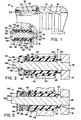
- the disc brake includes a rotor 10 to be braked and a caliper assembly 12.
- a pair of friction elements 14 and i6 are carried by a torque member 18 adjacent the rotor 10 in a conventional manner.
- the friction element 14 is commonly referred to as the inner friction clement and the friction element 16 is commonly referred to as the outer friction element.
- the caliper assembly forms a cylinder 20 for receiving a movable piston 22.
- a port 24 leads to the cylinder 20 to communicate fluid pressure thereto during braking.
- the caliper assembly also forms a leg 26 with an axially extending opening 28 for receiving the pin assembly 30.
- the pin assembly 30 comprises a resilient bushing 32 secured to caliper leg 26, a bolt 34 threadably secured to the torque member 18, a sleeve 36 slidably engageable with the resilient bushing 32 and a resilient member or coil spring 38 engaging the sleeve 36 and the bolt 34.
- the resilient bushing 32 includes radially extending ears 40 and 42 engageable with the leg 26 to secure the resilient bushing to the caliper leg 26.
- a plurality of inwardly extending ribs 44 frictionally engage the sleeve 3G and an axially extending skirt 46 is engageable with the bolt 34.
- the bolt 34 is provided with a threaded end 48 and a reduced diameter section 50 carries a spacer 52.
- a radially extending head 54 cooperates with the spacer 52 to define a recess 56 having a predetermined axial length.
- the recess 56 also receives the sleeve 36 and the coil spring 38 is disposed substantially within an inner recess 58 on the sleeve 36 to abut a shoulder 60 and the head 54. Consequently, in the rest position illustrated in Figure 1, the coil spring 38 biases the sleeve 36 toward the rotor 10 in abutment with the bolt spacer 52 so as to define a predetermined axial clearance 62 between the bolt 34 and the sleeve 36.
- the sleeve 36 also forms an outer recess 64 substantially adjacent the torque member 18 and a sealing member 66 is disposed within the outer recess 64 in engagement with the sleeve 36.
- the sealing member 66 also engages the spacer 52 to prevent contaminates from entering the bore 68 defined by the sleeve 36.
- the skirt 46 sealingly engages the head 54 to also prevent contaminates from entering the bore 70 defined by the resilient bushing 32.
- a sleeve tab 72 within outer recess 64 cooperates with the sealing member ' 66 so that movement of the sleeve relative to the bolt 34 also moves the scaling member 66 relative to the bolt and spacer.
- the sleeve bore 68 is larger in diameter than a main body portion of the bolt 34 so that a radial clearance 74 is provided between the bolt 34 and the bore 68.
- the clearance 74 permits lateral adjustment of the pin assembly 30 within the caliper opening 28 to align the bolt with the torque member opening receiving end 48.
- the fluid pressure within cylinder 20 acts against the caliper assembly 12 to move the caliper assembly 12 to the left. Movement of the caliper assembly 12 to the left causes the resilient bushing 32 to move to the left and the tight engagement between the resilient bushing 32 and the sleeve 36 results in the sleeve 36 also moving to the left relative to the bolt 34. Consequently, the coil spring 38 is compressed and the left end of the sleeve is moved into abutment with the bolt head 54 to take up the clearance 62.
- the caliper assembly 12 is also moving the outer friction element 16 into engagement with the rotor 10 so that both friction elements tightly engage the rotor to brake the same.
- the fluid pressure within the cylinder 20 is vented out ot the port 24 so that the clamping forces between the friction elements are eliminated.
- a retraction seal 80 biases the piston 22 to withdraw into the cylinder to release the inner friction element from its tight engagement with the rotor 10.
- the resilient bushing 32 will remain fixed relative to the sleeve 36 so that they will move in unison.
- the friction forces at the interface between the resilient bushing 32 and the sleeve 36 are overcome by the caliper assembly reaction forces so that the resilient bushing 32 is moved to the left on the sleeve 36 during braking and after the sleeve 36 abuts the bolt head 54.
- the skirt 46 is provided with slight interference fit with the bolt head 54 so that the skirt 46 can easily slide relative to the bolt head 54.
- the sleeve 36 and seal 66 will only move relative to the bolt through a distance equal to clearance 62, whereas the resilient bushing 32 will be adjusted continuously relative to the sleeve 36 to accommodate lining wear for the friction elements.
- the left end 34 of bolt 134 is provided with a recess 8G carrying a seal 88 and the head 154 is a separate part from the bolt 134.
- a snap ring 90 retains the head 154 on the bolt 134.
- the spacer 152 is integrally formed with the bolt 134.
- the resilient bushing 232 is provided with an annular groove 92 substantially adjacent the caliper leg 23 and axially spaced from the portion 94 of skirt 46 which is adapted to slide over the bolt head 15 1 1 .
- the head 154 is retained on the bolt 234 by staking the latter at 236.
- This structure provides a higher friction force at the interface between the resilient bushing 232 and the sleeve 36 so that adjustment of the resilient bushing relative to the sleeve will only occur when the friction elements are worn.
- the spring 96 is also believed to provide a more reliable friction force between the sleeve and resilient bushing opposing movement therebetween.
- each pin assembly could be provided with the controlled retraction structure described above.
Landscapes
- Engineering & Computer Science (AREA)
- General Engineering & Computer Science (AREA)
- Mechanical Engineering (AREA)
- Braking Arrangements (AREA)
Applications Claiming Priority (2)
| Application Number | Priority Date | Filing Date | Title |
|---|---|---|---|
| US06/307,918 US4436186A (en) | 1981-10-02 | 1981-10-02 | Disc brake assembly |
| US307918 | 1981-10-02 |
Publications (2)
| Publication Number | Publication Date |
|---|---|
| EP0076729A1 true EP0076729A1 (fr) | 1983-04-13 |
| EP0076729B1 EP0076729B1 (fr) | 1986-05-28 |
Family
ID=23191734
Family Applications (1)
| Application Number | Title | Priority Date | Filing Date |
|---|---|---|---|
| EP82401740A Expired EP0076729B1 (fr) | 1981-10-02 | 1982-09-27 | Frein à disque |
Country Status (8)
| Country | Link |
|---|---|
| US (1) | US4436186A (fr) |
| EP (1) | EP0076729B1 (fr) |
| JP (1) | JPS5872736A (fr) |
| AU (1) | AU547084B2 (fr) |
| CA (1) | CA1174610A (fr) |
| DE (1) | DE3271397D1 (fr) |
| ES (1) | ES516155A0 (fr) |
| MX (1) | MX154684A (fr) |
Cited By (10)
| Publication number | Priority date | Publication date | Assignee | Title |
|---|---|---|---|---|
| FR2534336A1 (fr) * | 1982-10-09 | 1984-04-13 | Teves Gmbh Alfred | Frein a disque a garnitures partielles pour vehicule automobile et moyens de rattrapage d'usure des garnitures utilises dans ce frein |
| GB2142698A (en) * | 1983-07-01 | 1985-01-23 | Teves Gmbh Alfred | Spot-type disc brake |
| DE3403297A1 (de) * | 1984-01-31 | 1985-08-01 | Deutsche Perrot-Bremse Gmbh, 6800 Mannheim | Gleitsattel-scheibenbremse |
| FR2563594A1 (fr) * | 1984-04-26 | 1985-10-31 | Dba | Frein a disque a etrier coulissant |
| GB2160601A (en) * | 1984-05-10 | 1985-12-24 | Aisin Seiki | Disc brake |
| DE3510372A1 (de) * | 1985-03-22 | 1986-09-25 | Alfred Teves Gmbh, 6000 Frankfurt | Schwimmsattel-teilbelagscheibenbremse |
| GB2202287A (en) * | 1987-03-20 | 1988-09-21 | Automotive Products Plc | Disc brake |
| EP0468696A1 (fr) * | 1990-07-25 | 1992-01-29 | Lucas Industries Public Limited Company | Freins à disque |
| EP0645551A1 (fr) * | 1993-09-21 | 1995-03-29 | Sime Industrie | Frein à disque à montage coulissant |
| CN108779820A (zh) * | 2016-04-13 | 2018-11-09 | 威伯科欧洲有限责任公司 | 盘式制动器,尤其是用于商用车的盘式制动器 |
Families Citing this family (24)
| Publication number | Priority date | Publication date | Assignee | Title |
|---|---|---|---|---|
| US4480724A (en) * | 1983-02-22 | 1984-11-06 | General Motors Corporation | Disc brake caliper mounting suspension |
| US4596313A (en) * | 1985-03-26 | 1986-06-24 | Clark Equipment Company | Centering device for floating caliper brakes |
| US4715479A (en) * | 1986-06-17 | 1987-12-29 | Hayes Industrial Brake, Inc. | Retraction type support assembly for a floating caliper disc brake |
| DE3707156C2 (de) * | 1987-03-06 | 1998-09-24 | Teves Gmbh Alfred | Anordnung zum Lüften einer Schwimmsattel-Teilbelagscheibenbremse |
| US4887696A (en) * | 1988-11-30 | 1989-12-19 | The B. F. Goodrich Company | Disc brake |
| IT1236477B (it) * | 1989-12-06 | 1993-03-09 | Carraro Spa | Freno a dischi con dispositivo di recupero di gioco |
| DE4119928C2 (de) * | 1991-06-17 | 2000-11-30 | Perrot Bremse Gmbh Deutsche | Gleitsattel-Scheibenbremse mit Rückstelleinrichtung |
| EP0684400B1 (fr) * | 1994-09-07 | 1999-01-27 | Hiroyuki Maeda | Frein à disque à êtrier flottant |
| US5529150A (en) * | 1995-05-16 | 1996-06-25 | Hayes Industrial Brake, Inc. | Parking brake |
| DE19946677A1 (de) * | 1999-09-29 | 2001-05-03 | Knorr Bremse Systeme | Schiebesattel-Scheibenbremse |
| DE19946681A1 (de) * | 1999-09-29 | 2001-05-03 | Knorr Bremse Systeme | Schiebesattel-Scheibenbremse |
| US6481542B2 (en) | 2001-02-19 | 2002-11-19 | Meritor Heavy Vehicle Systems, Llc. | Brake adjuster |
| US6397983B1 (en) * | 2001-02-23 | 2002-06-04 | Akebono Corporation North America | Automatic adjustment for disc brake pad |
| US6533079B2 (en) * | 2001-07-19 | 2003-03-18 | Robert Bosch Corporation | Disc brake |
| DE102004029462A1 (de) * | 2004-06-18 | 2006-01-05 | Continental Teves Ag & Co. Ohg | Schwimmsattel-Scheibenbremse mit Bolzenführungen |
| DE102006053183A1 (de) * | 2006-11-09 | 2008-05-15 | Knorr-Bremse Systeme für Nutzfahrzeuge GmbH | Scheibenbremse, insbesondere für ein Nutzfahrzeug |
| US20080245621A1 (en) * | 2007-04-05 | 2008-10-09 | Delphi Technologies, Inc. | Dual disc brake assembly |
| DE102012006111A1 (de) * | 2012-03-26 | 2013-09-26 | Knorr-Bremse Systeme für Nutzfahrzeuge GmbH | Scheibenbremse, insbesondere für ein Nutzfahrzeug |
| DE102012006083A1 (de) * | 2012-03-26 | 2013-09-26 | Knorr-Bremse Systeme für Nutzfahrzeuge GmbH | Scheibenbremse, insbesondere für ein Nutzfahrzeug |
| CN103486168B (zh) * | 2013-09-23 | 2015-11-18 | 湖北皓德车桥有限公司 | 一种用于多盘湿式制动器的间隙自调装置 |
| CN103883647B (zh) * | 2014-04-01 | 2016-02-10 | 武汉轻工大学 | 直驱转台薄壁制动套及制动方法 |
| EP3169910B1 (fr) * | 2014-07-16 | 2018-06-20 | Freni Brembo S.p.A. | Ensemble de dispositif de rétraction de plaquette pour disque de freinage |
| US10871197B2 (en) | 2017-10-13 | 2020-12-22 | Akebono Brake Industry Co., Ltd | Brake pad retraction device |
| US11773928B2 (en) * | 2020-12-14 | 2023-10-03 | Arvinmeritor Technology, Llc | Brake assembly having a guide pin assembly |
Citations (3)
| Publication number | Priority date | Publication date | Assignee | Title |
|---|---|---|---|---|
| US4200173A (en) * | 1978-08-01 | 1980-04-29 | Kelsey-Hayes Company | Sliding caliper disc brake |
| GB2037385A (en) * | 1978-11-16 | 1980-07-09 | Akebono Brake Ind | Caliper mounitn arrangement for a disc brake assembly |
| EP0033276A1 (fr) * | 1980-01-28 | 1981-08-05 | The Bendix Corporation | Ensemble de frein à disque |
Family Cites Families (2)
| Publication number | Priority date | Publication date | Assignee | Title |
|---|---|---|---|---|
| JPS5569328A (en) * | 1978-11-16 | 1980-05-24 | Akebono Brake Ind Co Ltd | Caliper guide mechanism of disk brake |
| JPS5628328A (en) * | 1979-08-15 | 1981-03-19 | Toyota Motor Corp | Pin slide type disk brake |
-
1981
- 1981-10-02 US US06/307,918 patent/US4436186A/en not_active Expired - Lifetime
-
1982
- 1982-05-13 CA CA000402883A patent/CA1174610A/fr not_active Expired
- 1982-09-27 AU AU88748/82A patent/AU547084B2/en not_active Ceased
- 1982-09-27 DE DE8282401740T patent/DE3271397D1/de not_active Expired
- 1982-09-27 EP EP82401740A patent/EP0076729B1/fr not_active Expired
- 1982-09-30 MX MX194594A patent/MX154684A/es unknown
- 1982-10-01 ES ES516155A patent/ES516155A0/es active Granted
- 1982-10-01 JP JP57171090A patent/JPS5872736A/ja active Granted
Patent Citations (3)
| Publication number | Priority date | Publication date | Assignee | Title |
|---|---|---|---|---|
| US4200173A (en) * | 1978-08-01 | 1980-04-29 | Kelsey-Hayes Company | Sliding caliper disc brake |
| GB2037385A (en) * | 1978-11-16 | 1980-07-09 | Akebono Brake Ind | Caliper mounitn arrangement for a disc brake assembly |
| EP0033276A1 (fr) * | 1980-01-28 | 1981-08-05 | The Bendix Corporation | Ensemble de frein à disque |
Cited By (16)
| Publication number | Priority date | Publication date | Assignee | Title |
|---|---|---|---|---|
| FR2534336A1 (fr) * | 1982-10-09 | 1984-04-13 | Teves Gmbh Alfred | Frein a disque a garnitures partielles pour vehicule automobile et moyens de rattrapage d'usure des garnitures utilises dans ce frein |
| GB2142698A (en) * | 1983-07-01 | 1985-01-23 | Teves Gmbh Alfred | Spot-type disc brake |
| DE3403297A1 (de) * | 1984-01-31 | 1985-08-01 | Deutsche Perrot-Bremse Gmbh, 6800 Mannheim | Gleitsattel-scheibenbremse |
| FR2558911A1 (fr) * | 1984-01-31 | 1985-08-02 | Perrot Bremse Gmbh Deutsche | Frein a disque a etrier coulissant |
| GB2153464A (en) * | 1984-01-31 | 1985-08-21 | Perrot Bremse Gmbh Deutsche | Sliding saddle disc brake |
| FR2563594A1 (fr) * | 1984-04-26 | 1985-10-31 | Dba | Frein a disque a etrier coulissant |
| EP0165088A1 (fr) * | 1984-04-26 | 1985-12-18 | BENDIX France | Frein à disque à étrier coulissant |
| GB2160601A (en) * | 1984-05-10 | 1985-12-24 | Aisin Seiki | Disc brake |
| DE3510372A1 (de) * | 1985-03-22 | 1986-09-25 | Alfred Teves Gmbh, 6000 Frankfurt | Schwimmsattel-teilbelagscheibenbremse |
| GB2202287A (en) * | 1987-03-20 | 1988-09-21 | Automotive Products Plc | Disc brake |
| GB2202287B (en) * | 1987-03-20 | 1991-03-20 | Automotive Products Plc | Disc brakes |
| EP0468696A1 (fr) * | 1990-07-25 | 1992-01-29 | Lucas Industries Public Limited Company | Freins à disque |
| US5217093A (en) * | 1990-07-25 | 1993-06-08 | Lucas Industries Public Limited Company | Disc brakes |
| EP0645551A1 (fr) * | 1993-09-21 | 1995-03-29 | Sime Industrie | Frein à disque à montage coulissant |
| FR2710379A1 (fr) * | 1993-09-21 | 1995-03-31 | Sime Ind | Frein à disque à montage coulissant. |
| CN108779820A (zh) * | 2016-04-13 | 2018-11-09 | 威伯科欧洲有限责任公司 | 盘式制动器,尤其是用于商用车的盘式制动器 |
Also Published As
| Publication number | Publication date |
|---|---|
| EP0076729B1 (fr) | 1986-05-28 |
| DE3271397D1 (en) | 1986-07-03 |
| JPS5872736A (ja) | 1983-04-30 |
| ES8308977A1 (es) | 1983-10-01 |
| AU8874882A (en) | 1983-04-14 |
| ES516155A0 (es) | 1983-10-01 |
| MX154684A (es) | 1987-11-16 |
| AU547084B2 (en) | 1985-10-03 |
| US4436186A (en) | 1984-03-13 |
| JPH031534B2 (fr) | 1991-01-10 |
| CA1174610A (fr) | 1984-09-18 |
Similar Documents
| Publication | Publication Date | Title |
|---|---|---|
| US4436186A (en) | Disc brake assembly | |
| US4458790A (en) | Caliper mounting suspension | |
| US4375842A (en) | Disc brake caliper piston and housing retraction and knockback control mechanism | |
| EP3169910B1 (fr) | Ensemble de dispositif de rétraction de plaquette pour disque de freinage | |
| EP0151277B1 (fr) | Un assemblage de frein à disque | |
| EP0061954B1 (fr) | Frein à disque comportant un dispositif à piston rétractable | |
| EP0975888B1 (fr) | Dispositif de reglage automatique interne sans axe pour piston de frein | |
| US4386682A (en) | Piston retraction and wear compensation for low-drag disc brakes | |
| EP0130137B1 (fr) | Moteur et dispositif de rattrapage de jeu d'un frein à disque | |
| GB1434369A (en) | Vehicle brake operating motor cylinders and to brake assemblies | |
| US3091310A (en) | Brake retractor mechanism | |
| USRE31878E (en) | Disc brake having a piston retraction assembly | |
| CA1045053A (fr) | Mecanisme de rappel de frein | |
| GB2099524A (en) | Disc brake | |
| US6397983B1 (en) | Automatic adjustment for disc brake pad | |
| US4446947A (en) | Sliding caliper disc brake | |
| US4685542A (en) | Disc brake assembly | |
| US3589479A (en) | Brake retractor mechanism | |
| US4373614A (en) | Disc brake assembly | |
| US5485902A (en) | Aircraft brake piston hydraulic adjuster assembly | |
| CA1145688A (fr) | Mecanisme irreversible pour la reprise du jeu aux freins | |
| US4242869A (en) | Master cylinder | |
| US4198825A (en) | Master cylinder | |
| GB2172350A (en) | Brake actuator | |
| US3760908A (en) | Disc brakes for vehicles |
Legal Events
| Date | Code | Title | Description |
|---|---|---|---|
| PUAI | Public reference made under article 153(3) epc to a published international application that has entered the european phase |
Free format text: ORIGINAL CODE: 0009012 |
|
| 17P | Request for examination filed |
Effective date: 19820930 |
|
| AK | Designated contracting states |
Designated state(s): DE FR GB IT |
|
| RAP1 | Party data changed (applicant data changed or rights of an application transferred) |
Owner name: ALLIED CORPORATION |
|
| ITF | It: translation for a ep patent filed | ||
| GRAA | (expected) grant |
Free format text: ORIGINAL CODE: 0009210 |
|
| AK | Designated contracting states |
Kind code of ref document: B1 Designated state(s): DE FR GB IT |
|
| REF | Corresponds to: |
Ref document number: 3271397 Country of ref document: DE Date of ref document: 19860703 |
|
| ET | Fr: translation filed | ||
| PGFP | Annual fee paid to national office [announced via postgrant information from national office to epo] |
Ref country code: GB Payment date: 19910806 Year of fee payment: 10 |
|
| PGFP | Annual fee paid to national office [announced via postgrant information from national office to epo] |
Ref country code: FR Payment date: 19910906 Year of fee payment: 10 |
|
| ITTA | It: last paid annual fee | ||
| PGFP | Annual fee paid to national office [announced via postgrant information from national office to epo] |
Ref country code: DE Payment date: 19910930 Year of fee payment: 10 |
|
| PLBE | No opposition filed within time limit |
Free format text: ORIGINAL CODE: 0009261 |
|
| STAA | Information on the status of an ep patent application or granted ep patent |
Free format text: STATUS: NO OPPOSITION FILED WITHIN TIME LIMIT |
|
| 26N | No opposition filed | ||
| PG25 | Lapsed in a contracting state [announced via postgrant information from national office to epo] |
Ref country code: GB Effective date: 19920927 |
|
| GBPC | Gb: european patent ceased through non-payment of renewal fee |
Effective date: 19920927 |
|
| PG25 | Lapsed in a contracting state [announced via postgrant information from national office to epo] |
Ref country code: FR Effective date: 19930528 |
|
| PG25 | Lapsed in a contracting state [announced via postgrant information from national office to epo] |
Ref country code: DE Effective date: 19930602 |
|
| REG | Reference to a national code |
Ref country code: FR Ref legal event code: ST |