EP0076708B1 - Druckkopf mit mehreren Düsen, für einen Tintenstrahldrucker nach Art der gesteuerten Tröpfchenerzeugung - Google Patents
Druckkopf mit mehreren Düsen, für einen Tintenstrahldrucker nach Art der gesteuerten Tröpfchenerzeugung Download PDFInfo
- Publication number
- EP0076708B1 EP0076708B1 EP19820305345 EP82305345A EP0076708B1 EP 0076708 B1 EP0076708 B1 EP 0076708B1 EP 19820305345 EP19820305345 EP 19820305345 EP 82305345 A EP82305345 A EP 82305345A EP 0076708 B1 EP0076708 B1 EP 0076708B1
- Authority
- EP
- European Patent Office
- Prior art keywords
- ink
- print head
- reservoir
- nozzles
- pressure
- Prior art date
- Legal status (The legal status is an assumption and is not a legal conclusion. Google has not performed a legal analysis and makes no representation as to the accuracy of the status listed.)
- Expired
Links
- 239000007788 liquid Substances 0.000 claims description 8
- 230000003068 static effect Effects 0.000 description 10
- 238000007639 printing Methods 0.000 description 4
- 239000000758 substrate Substances 0.000 description 3
- 238000005530 etching Methods 0.000 description 2
- 238000010276 construction Methods 0.000 description 1
- 230000007423 decrease Effects 0.000 description 1
- 230000003247 decreasing effect Effects 0.000 description 1
- 230000006866 deterioration Effects 0.000 description 1
- 230000000694 effects Effects 0.000 description 1
- 239000012530 fluid Substances 0.000 description 1
- 239000002241 glass-ceramic Substances 0.000 description 1
- 238000007641 inkjet printing Methods 0.000 description 1
- CNQCVBJFEGMYDW-UHFFFAOYSA-N lawrencium atom Chemical compound [Lr] CNQCVBJFEGMYDW-UHFFFAOYSA-N 0.000 description 1
- 238000000034 method Methods 0.000 description 1
- 238000012986 modification Methods 0.000 description 1
- 230000004048 modification Effects 0.000 description 1
- 239000002245 particle Substances 0.000 description 1
- 238000005086 pumping Methods 0.000 description 1
- 230000000630 rising effect Effects 0.000 description 1
- 229910001220 stainless steel Inorganic materials 0.000 description 1
- 239000010935 stainless steel Substances 0.000 description 1
Images

Classifications
-
- B—PERFORMING OPERATIONS; TRANSPORTING
- B41—PRINTING; LINING MACHINES; TYPEWRITERS; STAMPS
- B41J—TYPEWRITERS; SELECTIVE PRINTING MECHANISMS, i.e. MECHANISMS PRINTING OTHERWISE THAN FROM A FORME; CORRECTION OF TYPOGRAPHICAL ERRORS
- B41J2/00—Typewriters or selective printing mechanisms characterised by the printing or marking process for which they are designed
- B41J2/005—Typewriters or selective printing mechanisms characterised by the printing or marking process for which they are designed characterised by bringing liquid or particles selectively into contact with a printing material
- B41J2/01—Ink jet
- B41J2/17—Ink jet characterised by ink handling
- B41J2/175—Ink supply systems ; Circuit parts therefor
-
- B—PERFORMING OPERATIONS; TRANSPORTING
- B41—PRINTING; LINING MACHINES; TYPEWRITERS; STAMPS
- B41J—TYPEWRITERS; SELECTIVE PRINTING MECHANISMS, i.e. MECHANISMS PRINTING OTHERWISE THAN FROM A FORME; CORRECTION OF TYPOGRAPHICAL ERRORS
- B41J2/00—Typewriters or selective printing mechanisms characterised by the printing or marking process for which they are designed
- B41J2/005—Typewriters or selective printing mechanisms characterised by the printing or marking process for which they are designed characterised by bringing liquid or particles selectively into contact with a printing material
- B41J2/01—Ink jet
- B41J2/135—Nozzles
- B41J2/14—Structure thereof only for on-demand ink jet heads
- B41J2/14201—Structure of print heads with piezoelectric elements
- B41J2/14233—Structure of print heads with piezoelectric elements of film type, deformed by bending and disposed on a diaphragm
-
- B—PERFORMING OPERATIONS; TRANSPORTING
- B41—PRINTING; LINING MACHINES; TYPEWRITERS; STAMPS
- B41J—TYPEWRITERS; SELECTIVE PRINTING MECHANISMS, i.e. MECHANISMS PRINTING OTHERWISE THAN FROM A FORME; CORRECTION OF TYPOGRAPHICAL ERRORS
- B41J2/00—Typewriters or selective printing mechanisms characterised by the printing or marking process for which they are designed
- B41J2/005—Typewriters or selective printing mechanisms characterised by the printing or marking process for which they are designed characterised by bringing liquid or particles selectively into contact with a printing material
- B41J2/01—Ink jet
- B41J2/135—Nozzles
- B41J2/14—Structure thereof only for on-demand ink jet heads
- B41J2002/14379—Edge shooter
-
- B—PERFORMING OPERATIONS; TRANSPORTING
- B41—PRINTING; LINING MACHINES; TYPEWRITERS; STAMPS
- B41J—TYPEWRITERS; SELECTIVE PRINTING MECHANISMS, i.e. MECHANISMS PRINTING OTHERWISE THAN FROM A FORME; CORRECTION OF TYPOGRAPHICAL ERRORS
- B41J2202/00—Embodiments of or processes related to ink-jet or thermal heads
- B41J2202/01—Embodiments of or processes related to ink-jet heads
- B41J2202/07—Embodiments of or processes related to ink-jet heads dealing with air bubbles
Definitions
- This invention relates to a drop-on-demand type ink-jet print head, and more particularly to a multi-nozzle ink-jet print head having a plurality of nozzles arranged in line.
- ink when an ink droplet is not ejected, ink is maintained in a state of equilibrium, so that it does not flow through the nozzles, based on the balance between the static pressure of the ink in an ink reservoir and the surface tension of the ink in the nozzles. As the number of nozzles increases, the pressure difference tends to increase. This causes the pressure balance to be broken, whereby the ink flows out through the nozzles. Further, when the static pressure in the ink reservoir undergoes a change due to wide variations in operating conditions such as a large change in temperature, the state of equilibrium is broken, and the ink drips from the nozzles.
- the previously proposed multi-nozzle ink-jet print head is equipped with a pressure detector in the ink reservoir to detect the minute pressure change caused by the ink ejection.
- the output of the pressure detector is used for turning an automatic valve on or off in order to supply ink from the ink reservoir to pressure chambers. This arrangement complicates the print head.
- An object of the present invention is the provision of an ink jet print head which is less likely to suffer from the undesired dripping of the ink from the nozzles than are previously proposed heads.
- the object is achieved by a print head as defined in claim 1.
- a multi-nozzle ink-jet print head has previously been proposed in U.S. Patent Specification No. 4,158,847.
- This previously proposed head has a plurality of jets, each jet comprising a passage extending from a source of printing liquid to a printing location and each passage having a part incorporating a piezo-electric drive element and a corresponding part in a throttle plate which forms a part of a capillary filter device.
- the throttle plate restricts the flow of ink from an ink distributor to the passages.
- jets are fed via respective passages which are connected to a common ink supply path having a face exposed to ink in a reservoir without any restriction.
- a common ink supply path having a face in unrestricted direct contact with the ink in the reservoir minimises the effect of and variation in the level of ink in the reservoir and enables a smooth supply of ink to the jets to be maintained.
- a feature of the embodiments of the invention is the provision of a multi-nozzle ink-jet print head of drop-on demand type in which the ink is maintained in a state of equilibrium based upon the surface tension of the ink in the nozzles.
- Another feature is the provision of a multi-nozzle ink-jet print head having a comparatively simple construction.
- a further feature is the provision of a multi-nozzle ink-jet print head in which substantially no air enters via the nozzles to the pressure chambers.
- a multi-nozzle ink-jet print head of the drop-on-demand type in which a plurality of ink ejection channels having a plurality of nozzles and pressure chambers are connected to a common ink reservoir through an ink-supply path.
- the ink supply path has a dimension small enough to provide capillarity. The ink is supplied from the ink reservoir to the ejection chamber owing to the capillarity.
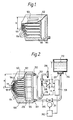
- the previously proposed multi-nozzle ink-jet printer shown in Fig. 1 comprises a plurality of ink ejection channels having pressure chambers 104 provided between nozzles 101 and an ink reservoir 105 in a substrate 100.
- a thin flexible upper plate 102 made of a glass ceramic or stainless steel is adhesively fixed on to the substrate 100.
- Electromechanical transducer elements 103 such as piezoelectric elements, are fastened to the upper plate 102 at positions coresponding to the pressure chambers 104.
- a multi-nozzle ink-jet head comprises nozzles 101, pressure chambers 104, and a common ink reservoir 105 provided on the substrate 100.
- capacity regions 111 of small volume between the nozzles 101 and the pressure chambers 104 to enable stable ink droplets to be formed and to prevent air bubbles entering via the nozzles 101 to the pressure chambers 104.
- an ink-supply path 200 of small depth between the pressure chambers 104 and the ink reservoir 105, there is an ink-supply path 200 of small depth.
- the ink-supply path 200 is formed by etching and has a depth 12 of about 0.04 to 0.4 mm. Owing to the capillarity of the path 200, ink can be supplied satisfactorily from the common ink reservoir 105 to the respective ink ejection channels, each of which comprises the pressure chamber 104, the capacity region 111, and the nozzle 101.
- the ink which is supplied from an inktank204, is temporarily stored in the ink reservoir 105 before rising through the ink supply path 200, owing to capillary action, and passing to the pressure chamber 104.
- ink of an amount corresponding to the amount ejected is supplied through theink supply path 200 to the pressure chamber 104. Therefore, ink can be supplied without being affected by variations in the static pressure of ink in the ink reservoir 105. This means that the number of the nozzles can be increased considerably compared with known arrangements.
- the ink reservoir 105 operates only to store the ink temporarily, it is unnecessary to control the static pressure of ink exactly and it is possible to employ a simplified control system.
- the variation in pressure in the pressure chamber 104 is increased, whereby the entry of air bubbles from the nozzles is rendered more likely. Air bubbles which might enter via the nozzles 101, however, remain in the capacity regions 111, and are thereby prevented from entering the pressure chambers 104. This means that the pressure chambers 104 can operate normally. The air bubbles remaining in the capacity region 111 can be easily pushed out by repeating the ejecting operation, thereby increasing the droplet forming frequency to about 3000 dots/sec.
- the pressure chambers 104 and the inksupply path 200 have the same depth from the viewpoint of etching cost. Further, in our experience, the best practical result is obtained when the ink supply path 200 has a depth 1 2 of 0.05 to 0.2 mm and a width w of 0.5 to 3 mm.
- the capacity region 111 it is desirable for the capacity region 111 to have a width of 1.3 to 3 times as wide as that of the nozzle 101 and a length of 1.0 to 8.0 mm.
- the best practical result has been obtained with a width of 0.13-0.3 mm and a length of 1.0-5.0 mm.
- the first embodiment further comprises an air vent 202 to which one end of a liquid level meter 203 is connected.
- the other end of the liquid level meter 203 is open to the air through a mesh filter 206 having a mesh opening of about 5 pm.
- a mesh filter may be provided in an outlet 207 of the ink tank 204 to prevent particles entering into the ink within the ink reservoir 105.
- the height of the surface 208 of ink in the liquid meter 203 represents the head pressure of the ink in the pressure chamber 104 and the ink reservoir 105.
- a difference in height between the nozzles 101 and the ink surface 208 represents the head pressure difference H' ofthe inkin the inkreservoir 105.
- h a permitted head pressure difference
- upper and lower level sensors 209 and 210 are positioned at upper and lower positions spaced apart by h and -h respectively from the reference level 0-0' representing the height of the nozzles 101.
- Each of the level sensors 209 and 210 may be constituted by two electrodes positioned apart from each other, or a combination of a light emitting diode (LED) and a photo transistor.
- LED light emitting diode
- the sensors 209 and 210 are coupled to a liquid level controller 301, which is connected to a valve driver 302.
- the valve driver 302 drives a valve 211 such as an electromagnetic valve to control the ink supply from an ink tank 204 to the ink reservoir 105 as will be described hereinafter.
- the ink in the ink tank 204 can be supplied to the ink reservoir 105 without using ink pressure means such as a pump.
- the controller 301 controls the valve driver 302 to turn on the valve 211 so that ink is supplied from the ink tank 204 through the pipe 205 and an inlet channel 201 to the ink reservoir 105, thereby to increase the static pressure in the ink reservoir 105.
- the controller 301 causes the valve driver 302 to turn off the valve 211 so that the supply of ink is stopped, thereby to stop the static pressure increasing.
- the controller 301 By ejecting the droplets during printing, the static pressure is decreased and the ink surface 208 is lowered.
- the controller 301 again controls the valve driver 302 to turn on the valve 211. This operation is repeated to maintain the head pressure difference H' in the range of ⁇ h.
- the second embodiment includes a liquid level sensor 401 having electrodes 401Aand 401 B, arranged spaced apartfrom each other in the ink reservoir 105, and a valve controller 402, instead of the sensors 209 and 210 and the combination of the controller 301 and the valve driver 302 employed in the first embodiment, respectively.
- the controller 402 causes the valve 211 to be turned on, thereby to supply ink from the ink tank 204 to the ink reservoir 105.
- the capacity regions 111 which act as a buffer or store between the nozzles 101 and the pressure chambers 104, may incorporate features designed to inhibit still further the entry of air and unwanted outflow of ink.
Landscapes
- Particle Formation And Scattering Control In Inkjet Printers (AREA)
- Ink Jet (AREA)
Claims (8)
Applications Claiming Priority (10)
| Application Number | Priority Date | Filing Date | Title |
|---|---|---|---|
| JP159945/81 | 1981-10-07 | ||
| JP159947/81 | 1981-10-07 | ||
| JP15994581A JPS5859856A (ja) | 1981-10-07 | 1981-10-07 | インクジエツト式印字ヘツド |
| JP15994781A JPS5859857A (ja) | 1981-10-07 | 1981-10-07 | インクジエツト式印字ヘツド |
| JP7198382A JPS58187367A (ja) | 1982-04-28 | 1982-04-28 | マルチノズル印字ヘツド |
| JP71986/82 | 1982-04-28 | ||
| JP7198682A JPS58187368A (ja) | 1982-04-28 | 1982-04-28 | マルチノズル印字ヘツド |
| JP71985/82 | 1982-04-28 | ||
| JP71983/82 | 1982-04-28 | ||
| JP7198582A JPS58187362A (ja) | 1982-04-28 | 1982-04-28 | インク圧力制御装置 |
Publications (3)
| Publication Number | Publication Date |
|---|---|
| EP0076708A2 EP0076708A2 (de) | 1983-04-13 |
| EP0076708A3 EP0076708A3 (en) | 1984-05-23 |
| EP0076708B1 true EP0076708B1 (de) | 1987-02-04 |
Family
ID=27524358
Family Applications (1)
| Application Number | Title | Priority Date | Filing Date |
|---|---|---|---|
| EP19820305345 Expired EP0076708B1 (de) | 1981-10-07 | 1982-10-07 | Druckkopf mit mehreren Düsen, für einen Tintenstrahldrucker nach Art der gesteuerten Tröpfchenerzeugung |
Country Status (2)
| Country | Link |
|---|---|
| EP (1) | EP0076708B1 (de) |
| DE (1) | DE3275366D1 (de) |
Families Citing this family (3)
| Publication number | Priority date | Publication date | Assignee | Title |
|---|---|---|---|---|
| US5812165A (en) * | 1991-08-29 | 1998-09-22 | Hewlett-Packard Company | Leak resistant ink-jet pen |
| US5489925A (en) * | 1993-05-04 | 1996-02-06 | Markem Corporation | Ink jet printing system |
| KR100374204B1 (ko) * | 2000-05-03 | 2003-03-04 | 한국과학기술원 | 2차원 노즐배치를 갖는 잉크젯 프린트헤드 및 그 제조방법 |
Family Cites Families (5)
| Publication number | Priority date | Publication date | Assignee | Title |
|---|---|---|---|---|
| US3946398A (en) * | 1970-06-29 | 1976-03-23 | Silonics, Inc. | Method and apparatus for recording with writing fluids and drop projection means therefor |
| US3835881A (en) * | 1972-12-29 | 1974-09-17 | Dick Co Ab | Method for controlling ink characteristics |
| US4158847A (en) * | 1975-09-09 | 1979-06-19 | Siemens Aktiengesellschaft | Piezoelectric operated printer head for ink-operated mosaic printer units |
| US4216477A (en) * | 1978-05-10 | 1980-08-05 | Hitachi, Ltd. | Nozzle head of an ink-jet printing apparatus with built-in fluid diodes |
| DE2842594C2 (de) * | 1978-09-29 | 1982-05-27 | Siemens AG, 1000 Berlin und 8000 München | Anordnung zum Versorgen eines Tintenschreibkopfes mit Tintenflüssigkeit |
-
1982
- 1982-10-07 EP EP19820305345 patent/EP0076708B1/de not_active Expired
- 1982-10-07 DE DE8282305345T patent/DE3275366D1/de not_active Expired
Also Published As
| Publication number | Publication date |
|---|---|
| DE3275366D1 (en) | 1987-03-12 |
| EP0076708A3 (en) | 1984-05-23 |
| EP0076708A2 (de) | 1983-04-13 |
Similar Documents
| Publication | Publication Date | Title |
|---|---|---|
| JP4036934B2 (ja) | インク配送システム | |
| JP4094709B2 (ja) | インクジェットプリンタ及びインクジェット・プリント方法 | |
| KR970007636B1 (ko) | 개선된 회복동작을 행할 수 있는 잉크제트장치 | |
| US5121130A (en) | Thermal ink jet printing apparatus | |
| US10632749B2 (en) | Fluid ejection device | |
| US10717274B2 (en) | Fluid ejection device | |
| US10766272B2 (en) | Fluid ejection device | |
| US10632743B2 (en) | Fluid ejection device | |
| JPH10157110A (ja) | サーマルインクジェット印刷システム | |
| US4549191A (en) | Multi-nozzle ink-jet print head of drop-on-demand type | |
| JP4146575B2 (ja) | 印刷装置 | |
| US6196671B1 (en) | Ink-jet cartridge for an ink jet printer having air ingestion control | |
| US4598303A (en) | Method and apparatus for operating an ink jet head of an ink jet printer | |
| JP4394418B2 (ja) | 流体噴射デバイスおよび流体を分配する方法 | |
| JPH11348305A (ja) | インクジェット記録装置 | |
| EP0076708B1 (de) | Druckkopf mit mehreren Düsen, für einen Tintenstrahldrucker nach Art der gesteuerten Tröpfchenerzeugung | |
| JPH04358844A (ja) | インクジェット記録装置 | |
| US6283576B1 (en) | Ventable ink jet printhead capping and priming assembly | |
| JP5071196B2 (ja) | 流体噴射装置及び流体噴射装置のメンテナンス方法 | |
| JPH03246055A (ja) | インクジェット記録装置およびインクジェット記録ヘッドの回復方法 | |
| US7651209B2 (en) | Flow passage | |
| US7168788B2 (en) | Drop ejection assembly | |
| EP1706271B1 (de) | Tropfenausstossanordnung | |
| JP2007301805A (ja) | 液体貯留容器及び液体吐出装置 | |
| JPS61233545A (ja) | ドロツプオンデマンド型インクジエツトヘツド |
Legal Events
| Date | Code | Title | Description |
|---|---|---|---|
| PUAI | Public reference made under article 153(3) epc to a published international application that has entered the european phase |
Free format text: ORIGINAL CODE: 0009012 |
|
| AK | Designated contracting states |
Designated state(s): DE FR GB |
|
| RAP1 | Party data changed (applicant data changed or rights of an application transferred) |
Owner name: NEC CORPORATION |
|
| PUAL | Search report despatched |
Free format text: ORIGINAL CODE: 0009013 |
|
| AK | Designated contracting states |
Designated state(s): DE FR GB |
|
| 17P | Request for examination filed |
Effective date: 19840614 |
|
| GRAA | (expected) grant |
Free format text: ORIGINAL CODE: 0009210 |
|
| AK | Designated contracting states |
Kind code of ref document: B1 Designated state(s): DE FR GB |
|
| REF | Corresponds to: |
Ref document number: 3275366 Country of ref document: DE Date of ref document: 19870312 |
|
| ET | Fr: translation filed | ||
| PLBE | No opposition filed within time limit |
Free format text: ORIGINAL CODE: 0009261 |
|
| STAA | Information on the status of an ep patent application or granted ep patent |
Free format text: STATUS: NO OPPOSITION FILED WITHIN TIME LIMIT |
|
| 26N | No opposition filed | ||
| PGFP | Annual fee paid to national office [announced via postgrant information from national office to epo] |
Ref country code: GB Payment date: 20011010 Year of fee payment: 20 Ref country code: FR Payment date: 20011010 Year of fee payment: 20 |
|
| PGFP | Annual fee paid to national office [announced via postgrant information from national office to epo] |
Ref country code: DE Payment date: 20011022 Year of fee payment: 20 |
|
| REG | Reference to a national code |
Ref country code: GB Ref legal event code: IF02 |
|
| PG25 | Lapsed in a contracting state [announced via postgrant information from national office to epo] |
Ref country code: GB Free format text: LAPSE BECAUSE OF EXPIRATION OF PROTECTION Effective date: 20021006 |
|
| REG | Reference to a national code |
Ref country code: GB Ref legal event code: PE20 Effective date: 20021006 |