EP0074922B1 - Vorrichtung zur Begrenzung des Drehwinkels bei Schraubengetrieben und Verwendung derselben - Google Patents
Vorrichtung zur Begrenzung des Drehwinkels bei Schraubengetrieben und Verwendung derselben Download PDFInfo
- Publication number
- EP0074922B1 EP0074922B1 EP82810355A EP82810355A EP0074922B1 EP 0074922 B1 EP0074922 B1 EP 0074922B1 EP 82810355 A EP82810355 A EP 82810355A EP 82810355 A EP82810355 A EP 82810355A EP 0074922 B1 EP0074922 B1 EP 0074922B1
- Authority
- EP
- European Patent Office
- Prior art keywords
- threaded spindle
- rotation
- axial
- sleeve
- cam
- Prior art date
- Legal status (The legal status is an assumption and is not a legal conclusion. Google has not performed a legal analysis and makes no representation as to the accuracy of the status listed.)
- Expired
Links
- 230000033001 locomotion Effects 0.000 claims abstract description 18
- 238000006073 displacement reaction Methods 0.000 claims abstract description 13
- 230000005540 biological transmission Effects 0.000 claims abstract description 6
- 230000008878 coupling Effects 0.000 claims description 5
- 238000010168 coupling process Methods 0.000 claims description 5
- 238000005859 coupling reaction Methods 0.000 claims description 5
- 239000012530 fluid Substances 0.000 claims description 4
- 230000001105 regulatory effect Effects 0.000 claims 2
- 230000000694 effects Effects 0.000 description 1
- 238000009434 installation Methods 0.000 description 1
- 239000012528 membrane Substances 0.000 description 1
Images

Classifications
-
- F—MECHANICAL ENGINEERING; LIGHTING; HEATING; WEAPONS; BLASTING
- F15—FLUID-PRESSURE ACTUATORS; HYDRAULICS OR PNEUMATICS IN GENERAL
- F15B—SYSTEMS ACTING BY MEANS OF FLUIDS IN GENERAL; FLUID-PRESSURE ACTUATORS, e.g. SERVOMOTORS; DETAILS OF FLUID-PRESSURE SYSTEMS, NOT OTHERWISE PROVIDED FOR
- F15B9/00—Servomotors with follow-up action, e.g. obtained by feed-back control, i.e. in which the position of the actuated member conforms with that of the controlling member
- F15B9/02—Servomotors with follow-up action, e.g. obtained by feed-back control, i.e. in which the position of the actuated member conforms with that of the controlling member with servomotors of the reciprocatable or oscillatable type
- F15B9/08—Servomotors with follow-up action, e.g. obtained by feed-back control, i.e. in which the position of the actuated member conforms with that of the controlling member with servomotors of the reciprocatable or oscillatable type controlled by valves affecting the fluid feed or the fluid outlet of the servomotor
- F15B9/12—Servomotors with follow-up action, e.g. obtained by feed-back control, i.e. in which the position of the actuated member conforms with that of the controlling member with servomotors of the reciprocatable or oscillatable type controlled by valves affecting the fluid feed or the fluid outlet of the servomotor in which both the controlling element and the servomotor control the same member influencing a fluid passage and are connected to that member by means of a differential gearing
-
- F—MECHANICAL ENGINEERING; LIGHTING; HEATING; WEAPONS; BLASTING
- F16—ENGINEERING ELEMENTS AND UNITS; GENERAL MEASURES FOR PRODUCING AND MAINTAINING EFFECTIVE FUNCTIONING OF MACHINES OR INSTALLATIONS; THERMAL INSULATION IN GENERAL
- F16H—GEARING
- F16H25/00—Gearings comprising primarily only cams, cam-followers and screw-and-nut mechanisms
- F16H25/18—Gearings comprising primarily only cams, cam-followers and screw-and-nut mechanisms for conveying or interconverting oscillating or reciprocating motions
- F16H25/20—Screw mechanisms
- F16H25/2015—Means specially adapted for stopping actuators in the end position; Position sensing means
Definitions
- the present invention relates to a device for limiting the angle of rotation in screw gears according to the preambles of independent patent claims 1 and 2 and to the use of this device according to the preamble of independent patent claim 3.
- a step-by-step rotary drive such as a stepping motor, which is connected to a lifting rotary valve.
- Such reciprocating valves consist of cylinders and pistons with two or four control edges in order to control the working piston either on one or two sides in a working cylinder. So that the control edges of the piston are axially displaced in the lifting rotary valve, a threaded spindle is threaded into the working piston so that rotation of the spindle translates into an axial displacement and fluid can be pressed into the working cylinder in order to axially shift the piston.
- Such arrangements are known as hydraulic boosters and are described, for example, in CH-A 549 163 or US-A 2 410 049.
- a return of the position of the working piston in the pressure cylinder is often provided in order to ensure a rapid and precise tracking of the working piston to the rotating movement.
- the control element for the position comparison is often a differential screw drive in which, for example, the angle of rotation of the control element is transmitted to a threaded spindle and an angle of rotation of the powerful output side is transmitted to a threaded nut.
- a change in the mutual position of the threaded spindle and threaded nut causes an axial displacement, which in turn is transmitted to the rotary valve and there causes a change in the position of the control edges.
- the rotary motion of the hydraulic output motor can be transmitted directly to the threaded nut or, according to CH-A 594141, the axial displacement of the working piston can be converted into a rotary motion by means of a high-helix lead screw.
- the axial displacement path in the direction of rotation is thus limited by axially abutting the collars (arranged) at the end of the recess on the cam.
- the two turned parts can clamp in both directions of rotation because nothing is said about the abutting abutment surfaces.
- the helical recess on the threaded spindle must be adapted to the thread.
- One way of changing the displacement of the path limitation is not specified.
- FIG. 1-3 show a differential screw gear 10 with a threaded sleeve 11 and a threaded spindle 12 and together the axis of rotation.
- the threaded sleeve 11 is indicated with a round rod 14 for returning the piston movement in a linear amplifier of the type described above, for example according to CH-A 594'141.
- This threaded sleeve 11 carries an extension sleeve 13 which has a radially inwardly projecting cam 15 with a flat stop surface on both sides.
- the threaded spindle 12 carries on a connecting shaft 16 to the drive shaft 20 a hollow cylinder 17 which has a radially outwardly projecting cam 18, 19 on each of the two end faces.
- a connecting shaft 16 to the drive shaft 20 a hollow cylinder 17 which has a radially outwardly projecting cam 18, 19 on each of the two end faces.
- the second exemplary embodiment according to FIGS. 4 to 6 again shows a differential screw drive 10 with a threaded sleeve 11 and a threaded spindle 12.
- the threaded sleeve 11 is rigidly connected to a round rod 14.
- the threaded sleeve 11 carries an extension sleeve 41 which is provided with at least one axial groove 42 for receiving a ball 43.
- an intermediate shaft 44 with a helically shaped groove 45 with a groove width corresponding to the ball diameter.
- the two end walls of the groove 45 which are not visible in the type shown, are arranged radially. It is easy to see that with this limitation of the angle of rotation, the axial displacement of the differential screw drive is limited by the circumferential path of the ball 43 and the groove 45. Since all stop surfaces are radial, the threaded spindle cannot jam in the threaded sleeve either.
- Each of these two embodiments makes it possible to freely select the path limitation between a smallest angle of rotation of approximately 360 ° and a multiple of this angle. However, it would also be possible to restrict the angle of rotation to parts of an entire revolution. In the exemplary embodiment according to FIG. 1, this could be made possible by two cams 18, 19 arranged offset in the circumferential direction or by two cams 15 on the hollow cylinder 13.
- a plurality of grooves 42 each with a ball 43, could be provided in the extension sleeve 41 in order to limit the displacement path of the screw mechanism, and two balls could also be inserted into the grooves in order to change the displacement path.
- Fig. 7 shows a linear amplifier (control device) 50 with a motor 51 (e.g. a stepping motor), for the setpoint input, an axially elastic coupling 52, and with a hydraulic control slide 53, a rotation angle limiter 54, a differential screw drive 55, a hydraulic working cylinder 56 with a piston 57 and the feedback of the actual value by means of a high-helix lead screw 80.
- a motor 51 e.g. a stepping motor
- the axially elastic coupling 52 consists of an elastic membrane 61, which is connected to the latter by means of crosswise arranged holding elements 62, 63 of coupling plates 64, 65 without play. This ensures that the setpoint value is transmitted to the differential screw drive 55 in the correct angle, even if this causes an axial displacement.
- the hydraulic control slide 53 operates in a known manner in a control slide housing 66 with a return 67 and control connection 68 and a leakage return 69.
- the housing 66 is provided with circumferential grooves for the supply and transfer of a fluid.
- the control slide 53 shown has a total of four control edges. Channels 70, 71 for guiding the fluid are present in the cylinder wall.
- the slider 53 is provided with an axial through bore 72 for carrying out a setpoint transmission shaft 73.
- the axial play of the slide is eliminated with a helical spring 74.
- the shaft 73 is connected to an intermediate shaft with a groove and further to the threaded spindle according to FIG. 4 as a rotation angle limiter 54 and to the differential screw drive 55.
- the piston 57 is arranged in the working cylinder 56.
- the two cylinder cavities 75, 76 are connected to the bores 70, 68 in a known manner.
- the piston 57 has a bore. 78 on, in which a spindle nut 79 with a steep thread for the spindle 80 is arranged. With this spindle 80, an axial displacement of the piston 57 is converted into a rotary movement.
- This spindle 80 is rigidly connected to the threaded sleeve 11 of the differential screw drive 55, as can also be seen in FIG. 4.
- screw gear 55 and angle limiter 54 are arranged in a main bearing 59, as a result of which the installation length is not changed despite this additional device.
- the very low mass inertia, freedom from play and compact design are of essential practical importance when using the device according to the invention.
Landscapes
- Engineering & Computer Science (AREA)
- General Engineering & Computer Science (AREA)
- Mechanical Engineering (AREA)
- Physics & Mathematics (AREA)
- Fluid Mechanics (AREA)
- Transmission Devices (AREA)
- Control Of Motors That Do Not Use Commutators (AREA)
- Gears, Cams (AREA)
Description
- Die vorliegende Erfindung betrifft eine Vorrichtung zur Begrenzung des Drehwinkels bei Schraubengetrieben gemäss den Oberbegriffen der unabhängigen Patentansprüche 1 und 2 sowie eine Verwendung dieser Vorrichtung gemäss dem Oberbegriff des unabhängigen Patentansprüch 3.
- Bei hydraulischen Verstärkern für Servosteuerungen, beispielsweise bei digital oder schrittweise betätigten elektrohydraulischen Antriebseinheiten, ist ein stufenweise arbeitender Rotationsantrieb, wie ein Schrittschaltmotor, vorhanden, der mit einem Hubdrehventil verbunden ist. Solche Hubdreventile bestehen aus Zylinder und Kolben mit zwei oder vier Steuerkanten, um in einem Arbeitszylinder den Arbeitskolben entweder ein- oder zweiseitig zu steuern. Damit im Hubdrehventil die Steuerkanten des Kolbens axial verschoben werden, ist eine Gewindespindel in den Arbeitskolben eingewindet, so dass sich eine Drehung der Spindel in eine axiale Verschiebung umsetzt und Fluid in den Arbeitszylinder gepresst werden kann, um den Kolben axial zu verschieben. Solche Anordnungen sind als hydraulische Verstärker bekannt und beispielsweise in der CH-A 549 163 oder der US-A 2 410 049 beschrieben.
- In Linearverstärken zur Umwandlung einer leistungsschwachen Drehbewegung eines Steuerorgans in eine axiale Bewegung ist oftmals eine Rückführung der Lage des Arbeitskolbens im Druckzylinder vorgesehen, um eine rasche und lagegenaue Nachführung des Arbeitskolbens an die Drehbewegung zu gewährleisten. Das Steuerorgan für den Lagevergleich ist vielfach ein Differenzschraubenantrieb, bei dem beispielsweise der Drehwinkel des Steuerorgans auf eine Gewindespindel und ein Drehwinkel der leistungsstarken Ausgangsseite auf eine Gewindemutter übertragen wird. Eine Aenderung der gegenseitigen Lage von Gewindespindel und Gewindemutter bewirkt eine axiale Verschiebung, die ihrerseits auf das Hubdrehventil übertragen wird und dort eine Aenderung der Lage der Steuerkanten bewirkt. Dabei kann, wie in der US-A 3 457 836 gezeigt, die Drehbewegung des hydraulischen Ausgangsmotors direkt auf die Gewindemutter übertragen werden oder gemäss der CH-A 594141 kann die axiale Verschiebung des Arbeitskolbens mittels einer Steilgewindespindel in eine Drehbewegung umgewandelt werden.
- Es ist bekannt bei derartigen Anordnungen zum Schutz vor grossen, von aussen wirkenden Kräften ein Schraubengetriebe zwischen Arbeitskolben und Steuerkolben einzubauen, damit diese Teile nicht starr gekoppelt sind, wie dies in den FR-A-21 19 724 und 2 316 461 beschrieben ist. In der FR-A-21 19 724 entsprechend den oberbegriffen der unabhängigen Ansprüche 1 und 2 ist eine axiale Wegbegrenzung vorgesehen, um zu verhindern, dass sich die Gewindespindel aus der Gewindelhülse herausschrauben kann. Dies wird durch eine schraubenlinienförmige Ausnehmung an der Gewindespindel und einen radial nach innen gerichteten Nocken an einer hülsenförmigen Verlängerung der Gewindehülse bewirkt. Damit ist der axiale Verschiebeweg in Drehrichtung durch axiales Aneinanderstossen der am Ende der Ausnehmung (angeordneten) Kragen an dem Nocken begrenzt. Die beiden Drehteile können in beiden Drehrichtungen festklemmen, denn über die aneinanderstoßenden Anschlagsflächen wird nichts ausgesagt. Weiterhin muß die schraubenlinienförmige Ausnehmung an der Gewindespindel dem Gewinde angepaßt sein. Eine höglichkeit, den Verschiebeweg der Wegbegrenzung zu verändern ist nicht angegeben.
- Es is daher eine Aufgabe der Erfindung, eine Vorrichtung zu schaffen, die eine Begrenzung des Drehwinkels bewirkt, bei der jedoch beidseits einer Mittelstellung ein genügend grosser Drehwinkel vorhanden ist, um die normalen Steuerbewegungen aufzunehmen, und durch die die Begrenzung nicht zu einem Klemmen und damit Festsitzen führen kann.
- Erfindungsgemäss wird dies durch eine Vorrichtung mit den Merkmalen in den kennzeichnenden Teilen der unabhängigen Patentansprüche 1 und 2 erreicht. Die besondere Ausgestaltung bei Verwendung in einer fluidischen Regelvorrichtung ist im kennzeichnenden Teil des Verwendungsanspruchs 3 angegeben.
- Ausführungsbeispiele der Erfindung werden nachfolgend anhand der Zeichnung erläutert. Es zeigen:
- Fig. 1 einen Längsschnitt durch eine erste Ausführungsform einer Vorrichtung zur Begrenzung der Drehbewegung,
- Fig. 2 eine Schnittansicht gemäss der Schnittlinie 11-11 in Fig. 1 zur Darstellung einer Endstellung.
- Fig. 3 eine Schnittansicht gemäss der Schnittlinie 111-111 in Fig. 1 zur Darstellung der zweiten Endstellung,
- Fig. 4 einen Längsschnitt ähnlich Fig. 1 durch eine zweite Ausführungsform mit einer Schraubennut,
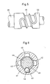
- Fig. 5 einen Ausschnitt eines Längsschnittes der Ausführungsform nach Fig. 4 und der Schraubennut in anderer Drehlage,
- Fig. 6 eine Schnittansicht nach der Schnittlinie VI-VI in Fig. 4, und
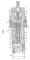
- Fig. 7 einen Längsschnitt durch einen Linearverstärker mit einer eingebauten Vorrichtung gemäss Fig. 4.
- Fig. 1-3 zeigen ein Differenzschraubengetriebe 10 mit einer Gewindehülse 11 und einer Gewindespindel 12 sowie gemeinsamet Drehachse. Die Gewindehülse 11 ist andeutungsweise mit einem Rundstab 14 für eine Rückführung der Kolbenbewegung in einem Linearverstärker der eingangs beschriebenen Art, beispielsweise gemäss der CH-A 594'141, verbunden. Diese Gewindehülse 11 trägt eine Verlängerungshülse 13, die einen radial nach innen vorstehenden Nocken 15 aufweist mit beidseitig ebener Anschlagfläche.
- Die Gewindespindel 12 trägt an einer Verbindungswelle 16 zur Antriebswelle 20 einen Hohlzylinder 17, der bei den beiden Endflächen je einen radial nach aussen vorstehenden Nocken 18, 19 aufweist. Durch Wahl des axialen Abstandes zwischen den beiden Nocken 18, 19 kann ein Drehwinkel zwischen nahezu 360° bis zu einem Mehrfachen dieses Winkels gewählt werden, so dass je nach Anwendungsgebiet ein längerer oder kürzerer Regelweg für ein Hubventil erlaubt werden kann. Die beiden Nocken 18, 19 mit ihren ebenen Anschlagsflächen stehen in den Endlagen in tangeutiales Richtung am Nocken 15 an, so das ein verklemmen bei axiale Bewegung nichtmöglich ist. Alle Ebenen der ebenen Anschlagsflächen an den Nocken 15, 18, 19 verlaufen durch die gemeinsame Drehachse.
- Das zweite Ausführungsbeispiel gemäss Fig. 4 bis 6 zeigt auch wieder einen Differenzschraubenantrieb 10 mit einer Gewindehülse 11 und einer Gewindespindel 12. Auch hier ist die Gewindehülse 11 mit einem Rundstab 14 starr verbunden. Die Gewindehülse 11 trägt in diesem Ausführungsbeispiel eine Verlängerungshülse 41, die mit wenigstens einer axialen Nut 42 für die Aufnahme einer Kugel 43 versehen ist.
- Zwischen der Antriebswelle 20 und der Gewindespindel 12 des Differenzschraubenantriebs 10 befindet sich eine Zwischenwelle 44 mit einer schraubenlinienförmig ausgebildeten Nut 45 mit einer dem Kugeldurchmesser entsprechenden Nutenbreite. Die beiden in der dargestellten Art nich ersichtlichen Endwände der Nut 45 sind radial angeordnet. Es ist leicht einzusehen, dass mit dieser Drehwinkel-Begrenzung die axiale Verschiebung des Differenzschraubenantriebs durch den Umfangsweg der Kugel 43 englang der Nut 45 begrenzt wird. In dem alle Anschlagflächen radial sind, kann die Gewindespindel in der Gewindehülse ebenfalls nicht verklemmen.
- Durch jede dieser beiden Ausführungsformen kann erreicht werden, dass die Wegbegrenzung zwischen einem kleinsten Drehwinkel von etwa 360° bis zu einem Mehrfachen dieses Winkels frei gewählt werden kann. Es wäre aber auch möglich, den Drehwinkel auf Teile einer ganzen Umdrehung zu beschränken. Im Ausführungsbeispiel gemäss Fig. 1 könnte dies durch zwei in Umfangsrichtung versetzt angeordnete Nocken 18, 19 oder durch zwei Nocken 15 am Hohlzylinder 13 ermöglicht werden.
- Entsprechend könnten im zweiten Ausführungsbeispiel nach Fig. 4 in der Verlängerungshülse 41 mehrere Nuten 42 mit je einer Kugel 43 vorgesehen werden, um hier den Verschiebeweg des Schraubengetriebes zu begrenzen, auch könnten zwei Kugeln in die Nuten eingelegt werden, um den Verschiebeweg zu verändern.
- Fig. 7 zeigt einen Linearverstärker (Regelvorrichtung) 50 mit einem Motor 51 (z.B. einen Schrittschalmotor), für die Sollwerteingabe, einer axialelastische Kupplung 52, sowie mit einem hydraulischen Steuerschieber 53, einem Drehwinkelbegrenzer 54, einem Differenzschraubenantrieb 55, einem hydraulischen Arbeitszylinder 56 mit Kolben 57 und der Istwert-Rückführung mittels einer Steilgewindespindel 80.
- Die axialelastische Kupplung 52 besteht aus einer elastischen Membran 61, die über kreuzweise angeordnete Halteelemente 62, 63 von Kupplungsscheiben 64, 65 mit diesen letzteren spielfrei verbunden ist. Dies gewährleistet eine winkelgetreue Uebertragung des Sollwertes auf den Differenzschraubenantrieb 55, auch wenn durch diesen eine axiale Verschiebung bewirkt wird.
- Der hydraulische Steuerschieber 53 arbeitet in bekannter Weise in einem Steuerschiebergehäuse 66 mit Rückführung 67 und Steueranschluss 68 und einer Leckagerückführung 69. Das Gehäuse 66 ist mit umlaufenden Nuten für die Zufuhr und Weiterleitung eines Fluids versehen.
- Der dargestellte Steuerschieber 53 weist insgesamt vier Steuerkanten auf. In der Zylinderwand sind Kanäle 70, 71 zur Leitung des Fluids vorhanden. Der Schieber 53 ist mit einer axialen Durchgangsbohrung 72 zur Durchführung einer Sollwert-Übertragungswelle 73 versehen. Mit einer Schraubenfeder 74 wird das axiale Spiel des Schiebers eliminiert.
- Die Welle 73 ist mit einer Zwischenwelle mit Nut und weiter mit der Gewindespindel gemäss Fig. 4 als Drehwinkelbegrenzer 54 und mit dem Differenzschraubenantrieb 55 verbunden.
- In dem Arbeitszylinder 56 ist der Kolben 57 angeordnet. Die beiden Zylinderhohlräume 75, 76 sind in bekannter Weise mit den Bohrungen 70, 68 verbunden. Der Kolben 57 weist eine Bohrung . 78 auf, in der eine Spindelmutter 79 mit Steilgewinde für die Spindel 80 angeordnet ist. Mit dieser Spindel 80 wird eine axiale Verschiebung des Kolbens 57 in eine Drehbewegung umgewandelt.
- Diese Spindel 80 ist mit der Gewindehülse 11 des Differenzschraubenantriebs 55 starr verbunden, wie ebenfalls aus Fig. 4 entnommen werden kann.
- Wie aus Fig. 7 insbesondere entnommen werden kann, sind Schraubengetriebe 55 und Drehwinkelbegrenzer 54 in einem Hauptlager 59 angeordnet, wodurch die Einbaulänge trotz dieser zusätzlichen Vorrichtung nicht verändert wird. Ausser den bereits in der Aufgabenstellung genannten Bedingungen, die durch die vorgeschlagenen Lösungen erfüllt sind, nämlich die klemmfreie Begrenzung des Steuerschieberhubes ohne die Kraftverbindung zu unterbrechen, sind die sehr geringe Massenträgheit, Spielfreiheit und kompakte Bauweise von wesentlicher praktischer Bedeutung bei der Verwendung der erfindungsgemässen Vorrichtung.
Claims (4)
Priority Applications (1)
| Application Number | Priority Date | Filing Date | Title |
|---|---|---|---|
| AT82810355T ATE33176T1 (de) | 1981-09-14 | 1982-08-27 | Vorrichtung zur begrenzung des drehwinkels bei schraubengetrieben und verwendung derselben. |
Applications Claiming Priority (2)
| Application Number | Priority Date | Filing Date | Title |
|---|---|---|---|
| CH5930/81 | 1981-09-14 | ||
| CH5930/81A CH657433A5 (de) | 1981-09-14 | 1981-09-14 | Vorrichtung zur begrenzung des drehwinkels bei schraubengetrieben und fluidische regeleinrichtung. |
Publications (3)
| Publication Number | Publication Date |
|---|---|
| EP0074922A2 EP0074922A2 (de) | 1983-03-23 |
| EP0074922A3 EP0074922A3 (en) | 1985-01-23 |
| EP0074922B1 true EP0074922B1 (de) | 1988-03-23 |
Family
ID=4301695
Family Applications (1)
| Application Number | Title | Priority Date | Filing Date |
|---|---|---|---|
| EP82810355A Expired EP0074922B1 (de) | 1981-09-14 | 1982-08-27 | Vorrichtung zur Begrenzung des Drehwinkels bei Schraubengetrieben und Verwendung derselben |
Country Status (4)
| Country | Link |
|---|---|
| EP (1) | EP0074922B1 (de) |
| AT (1) | ATE33176T1 (de) |
| CH (1) | CH657433A5 (de) |
| DE (1) | DE3278270D1 (de) |
Families Citing this family (13)
| Publication number | Priority date | Publication date | Assignee | Title |
|---|---|---|---|---|
| FR2584850A1 (fr) * | 1985-07-09 | 1987-01-16 | Lmt Radio Professionelle | Dispositif limiteur de rotation, en particulier pour une rotation superieure a un tour |
| FR2599780B1 (fr) * | 1986-06-04 | 1988-09-09 | Somfy | Dispositif d'actionnement electromecanique pour porte a deplacement coulissant |
| US5056414A (en) * | 1987-10-20 | 1991-10-15 | Nova-Werke Ag | Linear drive with hydraulic amplification |
| EP0961192A3 (de) * | 1998-05-28 | 2004-04-21 | Weber-Hydraulik GmbH | Betätigungsvorrichtung |
| EP1505468B1 (de) * | 1998-05-28 | 2006-07-19 | Weber-Hydraulik GmbH | Baueinheit |
| KR20030084303A (ko) * | 2002-04-26 | 2003-11-01 | 주식회사 메카테크 | 회전축 회전제한장치 |
| DE10232088A1 (de) * | 2002-07-15 | 2004-02-05 | Endress + Hauser Gmbh + Co. Kg | Verdrehsicherung, insbesondere für ein Meßumformergehäuse |
| DE102009036824A1 (de) * | 2009-08-10 | 2011-02-17 | Schaeffler Technologies Gmbh & Co. Kg | Verfahren zum Herstellen einer Gewindemutter eines Kugelgewindetriebes |
| US20130068053A1 (en) * | 2011-09-20 | 2013-03-21 | Goodrich Corporation | Actuator system and method |
| CN110805671B (zh) * | 2019-07-18 | 2023-08-11 | 庆安集团有限公司 | 一种旋转行程限位机构 |
| DE102019120205A1 (de) * | 2019-07-25 | 2021-01-28 | Zf Automotive Germany Gmbh | Drehungsbegrenzer, Lenkungssystem sowie Verfahren zum Begrenzen einer Drehbewegung bei einem Lenkungssystem |
| DE102019215479A1 (de) * | 2019-10-09 | 2021-04-15 | Volkswagen Aktiengesellschaft | Lenkvorrichtung und Kraftfahrzeug |
| DE102022116769A1 (de) * | 2022-07-05 | 2024-01-11 | Otto Egelhof Gmbh & Co. Kg | Regelventil, insbesondere elektrisch gesteuertes Regelventil |
Family Cites Families (3)
| Publication number | Priority date | Publication date | Assignee | Title |
|---|---|---|---|---|
| US2944436A (en) * | 1958-01-20 | 1960-07-12 | Ferro Stamping Co | Non-jamming actuated screw and nut comuination |
| JPS5129440Y1 (de) * | 1970-12-26 | 1976-07-24 | ||
| CH594141A5 (de) * | 1975-07-04 | 1977-12-30 | Sig Schweiz Industrieges |
-
1981
- 1981-09-14 CH CH5930/81A patent/CH657433A5/de not_active IP Right Cessation
-
1982
- 1982-08-27 EP EP82810355A patent/EP0074922B1/de not_active Expired
- 1982-08-27 DE DE8282810355T patent/DE3278270D1/de not_active Expired
- 1982-08-27 AT AT82810355T patent/ATE33176T1/de not_active IP Right Cessation
Also Published As
| Publication number | Publication date |
|---|---|
| CH657433A5 (de) | 1986-08-29 |
| DE3278270D1 (en) | 1988-04-28 |
| ATE33176T1 (de) | 1988-04-15 |
| EP0074922A2 (de) | 1983-03-23 |
| EP0074922A3 (en) | 1985-01-23 |
Similar Documents
| Publication | Publication Date | Title |
|---|---|---|
| EP0061415B1 (de) | Ventil für hydraulische Systeme | |
| DE3810804A1 (de) | Vorrichtung zur relativen winkelverstellung zwischen zwei in antriebsverbindung stehenden wellen | |
| EP0074922A2 (de) | Vorrichtung zur Begrenzung des Drehwinkels bei Schraubengetrieben und Verwendung derselben | |
| DE19635866C2 (de) | Schaltvorrichtung für ein Zahnräderwechselgetriebe | |
| DE2625909C2 (de) | Fluidischer Linearverstärker | |
| EP0393345A2 (de) | Hydraulische Steuereinrichtung | |
| DE1928143A1 (de) | Servoventil mit axial bewegbarem Ventilkolben | |
| DE1966073C3 (de) | Druckmittelübertrager an einer Werkzeugmaschine o.dgl | |
| EP0772746B1 (de) | Positionierantrieb, insbesondere für eine werkzeugmaschine | |
| DE2062134C3 (de) | Steuervorrichtung mit einer mit einem Kolben eines Arbeitszylinders verbundenen MeßspindeL | |
| WO2016041705A1 (de) | Drehmomentwandlereinrichtung sowie verfahren zum regeln eines flüssigkeitskreislaufs einer drehmomentwandlereinrichtung | |
| DE2947651C2 (de) | Einrichtung zur Stellungsrückführung der Steuerhülse eines Steuerventils einer hydraulischen Maschine | |
| DE2757612C3 (de) | Druckmittelbetriebener digitaler Positionierantrieb | |
| DE2919051C2 (de) | Hydrostatische Hilfskraftlenkung | |
| DE1576142C3 (de) | Hydraulisch oder pneumatisch betätig ter Drehantrieb | |
| DE3432279C2 (de) | ||
| DE2917298C2 (de) | Drehschiebereinrichtung zur Steuerung eines hydrostatischen Servoantriebs | |
| DE19851482A1 (de) | Hydraulische Lenkeinrichtung | |
| DE2002718A1 (de) | Servo-Betaetigungsvorrichtung | |
| DE2825827C2 (de) | Stellmotor mit Nachlaufsteuerung für hydraulische Verstellmaschinen | |
| DE3448382C2 (en) | Locking control for worm drive | |
| DE1750040A1 (de) | Hydraulischer Drehmomentverstaerker | |
| DE1284781B (de) | Reibradgetriebe mit kammartig ineinandergreifenden Reibscheiben | |
| DE2334552A1 (de) | Hydraulischer regler | |
| DE2404320C2 (de) |
Legal Events
| Date | Code | Title | Description |
|---|---|---|---|
| PUAI | Public reference made under article 153(3) epc to a published international application that has entered the european phase |
Free format text: ORIGINAL CODE: 0009012 |
|
| AK | Designated contracting states |
Designated state(s): AT CH DE FR GB LI |
|
| PUAL | Search report despatched |
Free format text: ORIGINAL CODE: 0009013 |
|
| AK | Designated contracting states |
Designated state(s): AT CH DE FR GB LI |
|
| 17P | Request for examination filed |
Effective date: 19841205 |
|
| 17Q | First examination report despatched |
Effective date: 19860808 |
|
| GRAA | (expected) grant |
Free format text: ORIGINAL CODE: 0009210 |
|
| AK | Designated contracting states |
Kind code of ref document: B1 Designated state(s): AT CH DE FR GB LI |
|
| REF | Corresponds to: |
Ref document number: 33176 Country of ref document: AT Date of ref document: 19880415 Kind code of ref document: T |
|
| GBT | Gb: translation of ep patent filed (gb section 77(6)(a)/1977) | ||
| REF | Corresponds to: |
Ref document number: 3278270 Country of ref document: DE Date of ref document: 19880428 |
|
| ET | Fr: translation filed | ||
| PLBE | No opposition filed within time limit |
Free format text: ORIGINAL CODE: 0009261 |
|
| STAA | Information on the status of an ep patent application or granted ep patent |
Free format text: STATUS: NO OPPOSITION FILED WITHIN TIME LIMIT |
|
| 26N | No opposition filed | ||
| PGFP | Annual fee paid to national office [announced via postgrant information from national office to epo] |
Ref country code: FR Payment date: 19910708 Year of fee payment: 10 |
|
| PGFP | Annual fee paid to national office [announced via postgrant information from national office to epo] |
Ref country code: AT Payment date: 19910709 Year of fee payment: 10 |
|
| PGFP | Annual fee paid to national office [announced via postgrant information from national office to epo] |
Ref country code: GB Payment date: 19910712 Year of fee payment: 10 |
|
| PGFP | Annual fee paid to national office [announced via postgrant information from national office to epo] |
Ref country code: CH Payment date: 19910717 Year of fee payment: 10 |
|
| PGFP | Annual fee paid to national office [announced via postgrant information from national office to epo] |
Ref country code: DE Payment date: 19910729 Year of fee payment: 10 |
|
| PG25 | Lapsed in a contracting state [announced via postgrant information from national office to epo] |
Ref country code: GB Effective date: 19920827 Ref country code: AT Effective date: 19920827 |
|
| PG25 | Lapsed in a contracting state [announced via postgrant information from national office to epo] |
Ref country code: LI Effective date: 19920831 Ref country code: CH Effective date: 19920831 |
|
| GBPC | Gb: european patent ceased through non-payment of renewal fee |
Effective date: 19920827 |
|
| PG25 | Lapsed in a contracting state [announced via postgrant information from national office to epo] |
Ref country code: FR Effective date: 19930430 |
|
| REG | Reference to a national code |
Ref country code: CH Ref legal event code: PL |
|
| PG25 | Lapsed in a contracting state [announced via postgrant information from national office to epo] |
Ref country code: DE Effective date: 19930501 |
|
| REG | Reference to a national code |
Ref country code: FR Ref legal event code: ST |