EP0074166B1 - Anschlussgerät und Mehrfachteststecker für ein Einschubrelais - Google Patents
Anschlussgerät und Mehrfachteststecker für ein Einschubrelais Download PDFInfo
- Publication number
- EP0074166B1 EP0074166B1 EP82303901A EP82303901A EP0074166B1 EP 0074166 B1 EP0074166 B1 EP 0074166B1 EP 82303901 A EP82303901 A EP 82303901A EP 82303901 A EP82303901 A EP 82303901A EP 0074166 B1 EP0074166 B1 EP 0074166B1
- Authority
- EP
- European Patent Office
- Prior art keywords
- terminal apparatus
- plug
- relay
- terminal
- terminals
- Prior art date
- Legal status (The legal status is an assumption and is not a legal conclusion. Google has not performed a legal analysis and makes no representation as to the accuracy of the status listed.)
- Expired
Links
Images


Classifications
-
- G—PHYSICS
- G01—MEASURING; TESTING
- G01R—MEASURING ELECTRIC VARIABLES; MEASURING MAGNETIC VARIABLES
- G01R1/00—Details of instruments or arrangements of the types included in groups G01R5/00 - G01R13/00 and G01R31/00
- G01R1/20—Modifications of basic electric elements for use in electric measuring instruments; Structural combinations of such elements with such instruments
- G01R1/206—Switches for connection of measuring instruments or electric motors to measuring loads
-
- H—ELECTRICITY
- H01—ELECTRIC ELEMENTS
- H01R—ELECTRICALLY-CONDUCTIVE CONNECTIONS; STRUCTURAL ASSOCIATIONS OF A PLURALITY OF MUTUALLY-INSULATED ELECTRICAL CONNECTING ELEMENTS; COUPLING DEVICES; CURRENT COLLECTORS
- H01R13/00—Details of coupling devices of the kinds covered by groups H01R12/70 or H01R24/00 - H01R33/00
- H01R13/66—Structural association with built-in electrical component
- H01R13/70—Structural association with built-in electrical component with built-in switch
- H01R13/703—Structural association with built-in electrical component with built-in switch operated by engagement or disengagement of coupling parts, e.g. dual-continuity coupling part
- H01R13/7031—Shorting, shunting or bussing of different terminals interrupted or effected on engagement of coupling part, e.g. for ESD protection, line continuity
- H01R13/7032—Shorting, shunting or bussing of different terminals interrupted or effected on engagement of coupling part, e.g. for ESD protection, line continuity making use of a separate bridging element directly cooperating with the terminals
Definitions
- the present invention relates to an improved terminal apparatus for a horizontal type case drawer relay having an improved contact mechanism for preventing a secondary side of a current transformer (hereinafter referred to as "CT") from opening, and also relates to an improved batch inserting type test plug used for the measuring and testing of internal elements of such a relay.
- CT current transformer
- a drawer type relay case can be either a vertical type case which is long in a vertical direction, or a horizontal type case which is long in a horizontal direction.
- the horizontal type case drawer relay has been developed only recently and uses print cards so that the relay becomes stationary.
- a plurality of print cards which extend in a vertical direction are arranged side by side and enclosed within the case.
- the case is long in the horizontal direction and is attached to a switchboard as a horizontal type case.
- the vertical type case drawer type relay is a relay box which contains mainly meehanica) elements, and a terminal apparatus is arranged on a lower or an upper portion of the relay.
- the case is long in the vertical direction and is attached to the switchboard vertically as a flush mounted drawout type.
- Relay elements in the horizontal type case can be made compact in comparison with those in a vertical type case.
- a plurality of relay elements, which are arranged side by side, can be enclosed in one case; therefore, the horizontal type case has advantages in that the occupied area in the switchboard can be significantly reduced. Accordingly, the horizontal type case is conveniently used in large-scale protective relay apparatuses.
- a terminal apparatus with a batch inserting type test plug which is installed in a vertical type case, allows for easy measuring and testing.
- the terminal apparatus becomes excessively large. It is also difficult to enclose such a test plug in a horizontal type case relay which has a compact configuration; therefore, such a test plug is not used for testing and measuring in a horizontal type case relay.
- a rear connector is installed to perform the required measuring and testing.
- the rear connector is fixedly attached to a rear surface of the switchboard.
- the terminals of the rear connector are connected so that a power source in an input side is connected to the switchboard by a relay side.
- a protective relay inserted from the front surface of the switchboard is connected to the rear connector through fittings between male and female connecting pieces and fixed to the switchboard side in a locked state. Testing of the protective relay only can be performed by drawing out the relay from the switchboard. Since the rear connector is connected as described above, measurement of relay operation speed, voltage, current and synthetic testing are performed inevitably when the rear connector is disposed at the rear surface of the switchboard.
- the rear surface of the switchboard is often crowded with connecting wires, and only a narrow space remains open.
- a hot-line portion may be exposed in the narrow space at the rear of the switchboard.
- Many measuring instruments cannot be used in testing the drawer type plug since care must be taken to the surroundings. Particularly, if a tool is left in the drawer type relay or falls into the relay by mistake, the tool may contact the hot-line portion and cause severe damage such as a short-circuit fault.
- Measuring and testing at the rear connector are performed by separately connecting clips to exposed terminals in a grasped state so that proper connection to the testing apparatus results. Accordingly, troublesome work is required, and there is always a fear of electric shock since one's fingers are liable to contact the hot-line portion.
- a plug used in the terminal apparatus comprises multiple poles assembled in one body. There are two types of plugs, a test plug used in testing and a connecting plug used in a non- testing state, i.e., during apparatus driving.
- Inserting the connecting plug in a bundle results in connection of a circuit in the switchboard side with a circuit in the relay side so that driving is started. If the apparatus required for testing is previously connected to the test plug which is inserted into the terminal apparatus in the bundle, testing can be performed simultaneously at multiple poles.
- Any plug can be operated at the front surface of the switchboard as described above; therefore, its operation is performed easily with safety, and the measuring and testing are simplified by simultaneous working of multiple poles.
- the testing apparatus is connected to a test plug, and two lead-in terminals per pole are required to branch the circuit to the relay side and to the switchboard side. Since a tightening tool is likely to be lost, the lead-in terminals are provided with a knob which can be rotatably tightened using one's fingers so that the use of the tightening tool within the switchboard can be avoided. In order to rotatably tighten the knob using one's fingers, the size of the knob must be considerably large. Since the test plug is formed arranging multiple poles in a line, the alignment distance becomes large as the number of poles increases. Furthermore, since many parts such as terminals and knobs are required which necessarily occupy a considerably large area, the testing apparatus cannot be made compact. Particularly in the horizontal relay type case containing stationary elements, many elements are enclosed in one case, and, therefore, the number of poles is numerous and further increases the size of the terminal apparatus.
- the area occupied by the terminal apparatus in the horizontal type case is rather small. Since print cards extending in the vertical direction are arranged side by side and enclosed within the case, the width of the terminal apparatus is also small, and the size of the structure to be enclosed adjacent the print cards is also small. Accordingly, the alignment distance between multiple poles in the test plug for the terminal apparatus must be enclosed within the extending height of the print card.
- both piggy-back knobs have different thread diameters for tightening.
- the smaller knob, with the smaller thread diameter can be tightly clamped.
- the larger knob, with the larger thread diameter has a small height and also a low number of threads, this latter knob is likely to be loosened.
- two types of connecting pieces, a larger one and a smaller one having different thread diameters, are required to connect between terminals. Proper use of both types of connecting pieces is troublesome.
- the lead wire connected to the testing apparatus during testing is provided with a so-called arrow-shaped chip at its top end. Since the arrow-shaped chip is likely to be readily detached due to loosening at the terminal portion, a larger length lead wire may be provided with a terminal (connecting piece) which has an attaching hole. However, such a connecting piece cannot be inserted before removing both knobs. Also, it is the larger knob which must be connected first, and treatment is, accordingly, inconvenient. The connecting piece for the larger knob is excessively large in size and is likely to be contacted with an adjacent terminal if there is a slight variation in the connecting piece. This is dangerous, particularly when using a connecting piece which has no insulation protection.
- connection is performed in accordance with a mark.
- the mark for the larger knob is hidden by the smaller knob and cannot be seen from above. Accordingly, two different marks are set forth for each position of the baseboard on which knobs are mounted, and the mark corresponding to the larger knob cannot be distinguished by visual observation. Since the mark may be hidden by the lead wire after connection, inconvenience occurs when the connection is checked.
- the alignment distance between electrode plates of multiple poles is large. Therefore, forming the baseboard as one body and appying the electrode plates to the baseboard is frequently used to achieve greater strength.
- a long, one-body baseboard may be warped or distorted by contraction or by aging of the resin which forms a part thereof. If the baseboard is warped, an abnormal condition occurs in the contacting state of the electrode plates which are used as contacts during the test plug insertion. Thus, not only a poor contacting state occurs, but, also, smooth inserting or detaching action of the test plug is obstructed.
- the width of the electrode plate may be decreased.
- potential transformer circuits hereinafter referred to as "PT" circuits
- CT circuits have elements which are required to carry a large current during opening. These large current elements exist in a mixed state in the electrode plate. Accordingly, the width of the electrode plates cannot be decreased significantly from the viewpoint of current capacity. Also, the electric insulation distance between electrode plates is considerably large. Therefore, the alignment distance cannot be reduced significantly and, accordingly, remains large.
- the maximum number of poles in the test plug for the conventional, vertical type case is restricted to 10 poles at present. If more than 10 are required, the terminal apparatus is arranged in two stages, that is, 10 poles on an uppermost stage and 10 poles on a lowermost stage of the vertical type case. Testing is thus performed by inserting the test plug for 10 poles to the upper and the lower stages, respectively. Furthermore, in the terminal apparatus of the relay, the power source at the input side is generally closed to a relay element side by inserting the abovementioned connecting plug into the terminal apparatus, and the power source is opened or disconnected from the relay element side by pulling the plug out of the terminal apparatus. Also, as indicated, the test plug may be used rather than the connecting plug when it is desired to conduct various kinds of measurements and tests.
- the terminal apparatus closes or opens an electric path between the power source and the relay element side by inserting or removing a plug as described above, the contacting state of the contacts in the terminal apparatus is very important. Particularly, in a CT circuit, if the CT secondary side is opened completely for only a brief moment, a serious electric fault occurs. Therefore, the CT secondary side cannot be allowed to open even for a moment. Furthermore, the CT circuit cannot be allowed to open even during a transient state while the connecting or the test plug is being inserted or removed when contacts within the terminal apparatus and the contacts on the plug bounce. Moreover, short- circuit closing contacts of the CT secondary side or circuit must be opened after completely connecting the current element of the relay side to the relay circuit.
- the CT secondary side must be short-circuited before opening the current element at the relay side. Such conditions must be automatically achieved in the contact mechanism of the terminal apparatus during the insertion and removal of the plug. Since the terminal apparatus has both CT circuits and PT circuits in a mixed state, a control mechanism to facilitate the installation and rearrangement of both circuits is.desirable for both workability and circuit change.
- the terminal apparatus when the terminal apparatus is enclosed within the relay, the internal electric contact mechanism is hidden by the casing of the relay, although an aperture for inserting a plug may be seen from the front surface of the relay.
- the terminal apparatus In order to inspect the contacting state of the short-circuited closing contacts which prevent the CT secondary side from opening, the terminal apparatus is inspected after being drawn out of the relay.
- an electric test can be performed without withdrawing the terminal apparatus by using an electric conduction test plug (not shown).
- Most operators perform overall tests through relay elements but do not take the trouble to inspect the internal electric contact mechanism of the terminal apparatus as part of the relay tests. Accordingly, the conventional terminal apparatus has disadvantages in that a poor contacting state of the short-circuit closing contacts is not found until a serious electric fault occurs.
- a terminal apparatus for a drawer type relay comprising upper and lower terminal boards having at least two plug inserting ports, a plurality of terminal pieces arranged on said upper and lower terminal boards for connection to an input side having a power source and a relay element side of said relay, a plurality of contact pieces each of which has one end fixed to an associated one of said terminal pieces, said contact pieces being pushed open as an electrode plate of a plug is inserted through said plug inserting ports, and stopping boards installed on said upper and lower terminal boards for contacting the free ends of said contact pieces to limit deflection of said free ends, characterised in that the terminal apparatus further includes one or more inspection windows each of which is located on a front side of an associated one of said plug inserting ports, an insulation rod having a thinner centre shaft portion and having one end fitted in a hole on said stopping board of said lower terminal board and its other end supported on and fixed to a lower side cover of said terminal apparatus, a compression spring, and a short bar loosely inserted about said thinner centre shaft portion of said
- This arrangement of inspection window near the plug inserting port allows for visual inspection of the internal electric contact mechanism from outside the terminal apparatus. Also opening of the CT secondary side while the plug is inserted or removed is automatically prevented.
- a batch inserting type test plug for use with a terminal apparatus as set forth above, said test plug comprising a plurality of electrode plates each having conduction plates embedded in plastic resin, connecting members for overlaying and connecting said plurality of electrode plates in a line, a group of first terminals and a group of second terminals arranged respectively for connection to a relay side and a switchboard side, a plurality of knobs screwed into said first and second terminals, and connecting pieces capable of being freely bent for connection to said first and second terminals, characterised in that the test plug further includes an upper resilient baseboard made of plastic resin and having a hollow interior space for holding said connected electrode plates, and a lower resilient baseboard for fixing said connected electrode plates to said upper baseboard, said group of first terminals and said group of second terminals being arranged respectively on said upper and lower baseboards and said first and second terminals being arranged in a zigzag pattern corresponding to the order of arrangement of said electrode plates.
- Figs. 1 and 2 are a front view of a protective relay and a terminal apparatus of a drawer type relay respectively.
- the protective relay of Fig. 1 comprises a horizontal case 101; a stationary internal element 102; a terminal apparatus 103 into which a test plug, according to the present invention, is accommodated; and a plug inserting port 4 located on the terminal apparatus 103.
- the terminal apparatus is shown without a relay box, and a relay body has been omitted in this figure.
- the terminal apparatus comprises an upper side cover 1 and a lower side cover 2, each made of plastic resin and divided to be symmetrically vertical.
- the plug inserting port 4 is formed on the front plate 3 for accommodating either a connecting or a testing plug, and an inspection window 5 is also formed on the front plate 3 for visually inspecting a contacting state of contacts.
- Fig. 3 is a transverse sectional view of the terminal apparatus taken along line III-III in Fig. 2, and Fig. 4 is an exploded perspective view of a lower part of the terminal apparatus illustrating an electric contact mechanism of the terminal apparatus.
- An upper terminal board 6 and a lower terminal board 7 are both made of plastic resin and divided vertically in symmetrical form. Each of the terminal boards 6, 7 is provided with a plurality of side walls 8 which provide electric insulation between the poles in each circuit.
- a stopping board 9 stops a free end 17 of a contact piece 16 as hereinafter described, and a mounting board 10 projects from both side surfaces of each of the terminal boards 6, 7.
- a mounting leg 11 is provided in the upper cover 1 and the lower cover 2.
- the upper and lower terminal boards 6, 7, the mounting board 10 and the mounting leg 11 are formed so that a common hole 12 passes through these elements when the upper terminal board 6 is overlaid on the lower terminal board 7.
- a bolt 13 is inserted through the common hole 12 and tightly clamped with a nut 14 to fix the upper and lower side covers integrally.
- a transparent plate 15 is fitted to the rear surface of the front plate 3, and this plate is made of transparent resin, such as polycarbonate, to seal the aperture of the inspection window 5. Electric contacts within the window 5 are, therefore, prevented from contamination and are visible from outside.
- a contact piece 16 is made of a resilient, conductive plate such a phosphor bronze plate. One end of the contact piece 16 is free and has a U-shaped tip which forms a triangular contact 17 (Fig. 5). The contact piece 16 also has a tapered contact surface near the center of the contact piece 16 to facilitate the plug insertion. The other end of the contact piece 16 is overlaid upon a terminal piece 19 of brass plate and tightly clamped to the upper terminal board 6 and the lower terminal board 7 using a plurality of screws 20.
- a terminal screw 21 (Fig. 3) connects to a relay element (not shown) through a lead wire (not shown).
- a compression spring 22 has one end engaged with a notch 23 on the lower terminal board 7 and the other end engaged with an embossment 24 on the contact piece 16, and this compression spring normally urges the contact piece 16 upwards.
- An insulation rod 27 has an upper center shaft portion 28 which is thinner than a lower shaft portion of the rod 27.
- the upper center shaft portion 28 is inserted in a loose state in the hole 26 at the center of the short bar 25.
- Another compression spring 29 has one end supported by the lower terminal board 7, and the other end pushes the short bar 25.
- Fig. 5 is a transverse, sectional view taken along line V-V in Fig. 3.
- the center shaft portion 28 of the insulation rod 27 is inserted and fixed to the hole 26 of the short bar 25, and the triangular contact 17 of the contact piece 16 rides on the short bar 25. Since the biasing strength of the contact piece 16 is stronger than the biasing strength of the compression spring 29, the short bar 25 is pushed upward by the contact piece 16 and stopped in a contacting state at the stopping board 9.
- the center shaft portion of the insulation rod 27 is fitted in a hole 30 on the lower terminal board 7, and the other end of the rod 27 contacts the lower side cover 2. Therefore, the rod 27 is held stably without pulling.
- Fig. 6 illustrates a state of the short bar when the biasing strength of the contact piece 16 is released from the state shown in Fig. 5.
- the short bar 25 is lowered by the compression spring 29 and stopped at the junction where the center shaft portion 28 extends from the insulation rod 27.
- Fig. 5 illustrates a short-circuit state of the CT secondary side
- Fig. 6 illustrates a short- circuit opening state of the CT secondary side.
- Fig. 7 is a transverse, sectional view taken along line VII-VII of Fig. 1, illustrating an inserted state of the test plug of the present invention.
- the external terminal made of brass plate
- Another external terminal 19 is fixed on the upper terminal board 6 and is connected to a protective relay element side.
- Each of the external terminals 19 is connected to the contact piece 16, which is made of phosphor bronze plate.
- An outer frame 114 encloses the lower terminal board 7 and the upper terminal board 6, which are symmetrically vertically divided, and the frame 114 also encloses the outer circumference of the front plate 3.
- the terminal apparatus 103 is clamped tightly using a clamping screw (not shown).
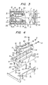
- Fig. 8 is a front view of one embodiment of a test plug 115 of the present invention
- Fig. 9 is a transverse, sectional view taken along line IX-IX of Fig. 8, illustrating the test plug in a vertically divided state.
- the test plug 115 comprises a lower and an upper baseboard 116, 117, and each board 116 is made of an elastic, plastic resin.
- the lower and upper baseboards 11, 117 are vertically symmetrically formed, and both the baseboards 116,117 have a thin outer circumference and a hollow inner space.
- a handle 118 can be gripped by an operator for operating the test plug 115.
- a notch 119 engages an outer circumference of an electrode plate 125, as hereinafter described, and a clamping washer 120 is also provided.
- the electrode plate 125 of the plug 115 is constructed so that a small thickness portion of the plug, along the direction of the arrow a-a in Fig. 9, is perpendicular to the longitudinal direction of the handle 118 shown by the arrow b-b in Fig. 8.
- the length of the handle 118 is significantly reduced, and, accordingly, the handle and the terminal apparatus can be made compact.
- the width of the electrode plate 125 in the direction of the arrow a-a is aligned along the longitudinal direction b-b of the handle 118, the length of the handle becomes excessively long, and the handle becomes unduly large. Therefore, the terminal apparatus accommodating the handle is also required to be large.
- a terminal 121 comprising a stepped bolt, is inserted in the clamping washer 120, and the stepped portion of the bolt is engaged with a hexagonal outer circumference of the clamping washer 120 to obstruct lateral rotation.
- a washer 122 is provided to obstruct any disconnection.
- a clamping screw 123 of the washer 122 also serves to connect a lead wire as hereinafter described, with the terminal 121.
- a knob 124 made of plastic resin with an outer circumference knurled, has a metal body which is embedded during molding and provided with a thread portion to be screwed to the terminal 121.
- the above-mentioned electrode plate 125 is made by plastic molding, and conductive plates 126, 127, each having a partly exposed thickness portion, are embedded in upper and lower sides of the electrode plate 125 during molding so that they form one body.
- a connecting member 128 has a projection at one side, and, at the other side, a hole is engaged with another projection so that, when a plurality of the individual electrode plates 125 are arranged in a line, adjacent projections and holes are engaged with each other, and the connecting members are aligned.
- a separating plate 129 is disposed between lead wires 130, which are flexible and can be bent freely.
- the conductive plate 126 is connected to a group of the terminals 121 which are attached to the side of the lower baseboard 116, and the conductive plate 127 is connected to a group of the terminals 121 which are attached to the side of the upper baseboard 117, respectively, in conformity with an arrangement order of the electrode plates 125.
- a mark label 131 designates the arrangement order of the electrode plates 125 in numerical notation, and one mark per one terminal is set forth near the terminal 121.
- a circuit nameplate 132 indicates the destination of a circuit in a switchboard side or a relay side.
- a screw 133 clamps the electrode plate 125. Starting from the state of Fig. 9, the electrode plate 125 is fitted in the notch 119 on the lower baseboard 116 and the upper baseboard 117 to contact the upper and lower boards 116, 117 closely. The screw 133 then tightly clamps the electrode plate 125 through a nut 134 to fix the electrode plate 125 integrally with both boards 116, 117.
- the electric path formed by inserting the test plug 115, as described above, into the terminal apparatus 103 is set forth below.
- the power source at the input side is connected to the terminal 121 of the lower baseboard 116 through the contact piece 16 of the external terminal 19, the conductive plate 126 of the electrode plate 125, and the lead wire 130.
- the path to the output side is connected to the external terminal 19 through the terminal 121 of the upper baseboard 117, the lead wire 130, the conductive plate 127 of the electrode plate 125, and the contact piece 16. That is, the terminal 121 at the side of the lower baseboard 116 is connected to the power source at the input side, and the terminal 121 at the side of the upper baseboard 117 is connected to the output side. Accordingly, if a testing apparatus is connected between the terminals 121 on both boards 116, 117, an electric path passes through the testing apparatus.
- the mark labels 131 indicate the arrangement order of the terminals 121 of the lower baseboard 116 and the terminals 121 of the upper baseboard 117, in conformity with the arrangement order of the electrode plates 125.
- the mark labels 131 are applied to both the lower baseboard 116 and the upper baseboard 117. Lead-in of circuits is distinguished so that circuits having the same mark can be connected in combination.
- the circuit nameplate 132 is applied to indicate a destination of the circuit when it is led in.
- a group of the terminals 121 of the lower baseboard 116 is indicated in the switchboard side, and the group of the terminals 121 of the upper baseboard 117 is indicated in the relay side.
- Fig. 10 is a plan view of a connecting piece 135 to connect between terminals.
- the connecting piece 135 comprises a resilient lead wire 136 which can be bent freely.
- Terminal pieces 137 are provided with a hole for insertion into the terminals 121 and are attached to both ends of the lead wire 136 by caulking.
- the connecting piece 135 is attached by removing the knob 124, inserting the terminal piece 137 of the connecting piece 135 to the terminal 121, and clamping the terminal piece 137 tightly. Since fine thread is used in the thread portion of the terminal 121 and an axial length of the thread portion is large, the connecting piece 135 can be clamped tightly. Connection for short circuit is effected using one type of lead wire 136 for connection, between either opposite polarity or the same polarity, since the length of the lead wire 136 is suited for both cases. In connection for the same polarity, the lead wire 136 is bent and stretched between the lower baseboard 116 and the upper baseboard 117. The paths between both the boards then extend in three directions - through both lateral surfaces of the test plug 115 and a space 138 adjacent the handle 118. Connection is performed through any path which is the shortest of the three.
- test plug 115 is inserted in a bundle so that testing in multiple poles can be performed simultaneously. In the embodiment shown, testing of 20 poles can be performed simultaneously.
- the external terminal 19 is connected to the other external terminal 19 by inserting the connecting plug (not shown) having a conductive plate inserting portion so that machines are driven.
- a batch inserting type test plug is constructed as described above, and the knobs 124 are arranged in a zigzag form from the right in an order corresponding to a circuit order of the electrode plates 125, an arrangement in extension of a line from the electrode plate 125 facilitates decision of circuit order in comparison to conventional double knobs where arrangement order cannot be decided by intuition.
- connection to the relay side or the switchboard side is also distinguished clearly since the lower baseboard 116 is connected to the switchboard side, and the upper baseboard 117 is connected to the relay side. Furthermore, correspondence of one mark to one terminal makes distinguishment easy and convenient at wiring and checking, in comparison with terminal mark indication in conventional combination terminals where tow marks are set forth together.
- the knobs 124 are unified in dimension and arranged alternately in a zigzag form.
- the small diameter thread portion of the knobs 124 permits the knobs to be well clamped.
- a fine thread diameter is used which prevents loosening after clamping, in comparison with normal threads.
- Unification of thread diameter results in unification of the connecting piece 135 having the terminal piece 137 and the lead wire 136, used in connection of both opposite polarity and same polarity. This improves workability and produces advantages in manufacturing.
- any terminal can be connected by removing one of the knobs 124 and rescrewing it again. Therefore, the troublesome work of removing two knobs, as seen in double-type knob constructions, is eliminated. Since the distance between the terminals 121 is widened due to the zigzag arrangement, and the metal portion of the knob 124 as well as the terminal piece 137 is hidden and protected by the outer circumference of the knob 124 after the knob 124 is tightened, any possible contact between adjacent bare connecting pieces is prevented securely.
- the knob 124 is singular, and the pitch is widened in comparison with a double-type knob, the singular knob is readily held by one's fingers.
- the conductive plates 126 and 127 each have a small thickness in the vertical direction and are integrally embedded during a plastic molding process. Therefore, the width of the electrode plate 125 arrangement is reduced.
- the distance required for electric insulation between adjacent electrode plates 125 is obtained by providing a small space between the plates 125 so that the electrode plates 125 are separated from each other, and a creeping distance is insulated sufficiently. Accordingly, when a number of the electrode plates 125 are arranged as shown in Fig. 8 (20 poles are shown), the arrangement distance in a line is significantly reduced, and multiple poles can be formed compactly and enclosed in a horizontal type case.
- the conventional plastic baseboard incorporated into one body has disadvantages in that contraction or aging of the resin may give rise to strain or distortion, thus resulting in a poor contacting state of the electrode plates. Also, the inserting or detaching action of the prior art, one body test plug is not performed smoothly. To the contrary, the electrode plate 125 of the present invention is formed individually, is small in width, and is made of resin so that little contraction occurs. Therefore, the strain caused by contraction does not result.
- the electrode plates 125 are each provided with the connecting members 128 and fitted together in a line.
- the lower baseboard 116 and the upper baseboard 117, which hold the electrode plates 125, are made of resilient plastic resin, and the interior of both boards 116, 117 is hollow.
- the terminals 121 and the knobs 124 are distributed in equal number on parts of the lower baseboard 116 and the upper baseboard 117, and, therefore, the occupied area on each board is reduced by half.
- the terminals and knobs are distributed on one baseboard, and the number of parts to be mounted is restricted; therefore, the solid overlaying structure, such as double knobs, is used in order to reduce the occupied area.
- test plug 115 is inserted from the front surface of the board for testing, as shown in Fig. 7, without drawing out the protective relay, as is done in the prior art. Thus, troublesome work for drawing-out is omitted. In testing, it is not necessary to attach clips individually with the rear connectors as in the prior art. Inserting the test plug 115 in a bundle with previously connected testing apparatuses enables simultaneous testing of multiple poles. Thus, treatment is simplified, and safety is guaranteed.
- the test plug 115 also can be used in a vertical type case, and, in the prior art, testing of multiple poles using two sets of 10 poles can be performed using one set. Accordingly, in the present invention, use of the test plug is simple, and the occupied area of the relay case can be reduced.
- the electric path of the terminal apparatus is set forth below. If the electrode plate 125 of the plug 115 is inserted in the plug inserting port 4, the contact surface 18 of the contact piece 16 on the upper terminal board 6 and the lower terminal board 7, shown in Fig. 3, is pushed open and contacts the electrode plate 125. Current at the input side, which is connected to the terminal piece 19 of the lower terminal board 7, flows to relay elements at the relay side which are connected to the terminal piece 19 of the upper terminal board 6.
- the triangular contact 17 of the free end of the contact piece 16 is guided by the tapered contact surface 18 and pushed open gradually as the plug 115 travels inward into the terminal apparatus. Even though the biasing force of the triangular contact 17 against the short bar 25 is released, the CT secondary side does not open since the compression spring 29 lowers the short bar 25 and keeps the short bar in contact with the triangular contact 17.
- the short-circuit state of the CT secondary side is held until the short bar 25 moves downward, and it is stopped at the junction where the center shaft portion 28 extends from the insulation rod 27 while the triangular contact 17 continues to move downward.
- the input side and the relay side are electrically connected through the electrode plate 125 of the plug 115, and the CT secondary side is short-circuited so that an electric path is formed in a mixed state. Therefore, the CT secondary side is not allowed to open, even during the transient state when the plug is being inserted or removed. If the plug 115 is further inserted from the stop state of the short bar 25, the triangular contact 17 is caused to be disengaged from the short bar 25, as shown in Fig. 6, with the result that the CT secondary side is opened. As is readily evident, the above-described short-circuit action also occurs during the plug 115 detaching operation, although it occurs in a reverse sequence.
- the short circuit of the CT secondary side must be opened after the current elements at the relay side are completely connected to the input side.
- the CT secondary side must be short-circuited before the current elements at the relay side are completely opened, or electrically disengaged from the input side, as the plug 115 is removed.
- a PT circuit rather than a CT circuit, can be readily formed. If the above-mentioned parts are added in the assembling sequence in Fig. 3, a PT circuit can be easily changed into a CT circuit.
- the lower terminal board 7 is provided with the hole 30 for inserting the center shaft 27, and a mounting hole for the compression spring 29 is provided so that the short-circuit parts can be installed to any circuit. Changing a PT circuit to a CT circuit, and vice versa, is, therefore, simple, and the treatment thereof is convenient.
- the contacting state of the short bar 25 and the triangular contact 17 are visible from outside the window 5 through the transport plate 15.
- Fig. 5 illustrates the short-circuit state of the CT secondary side
- Fig. 6 illustrates the short- circuit opening state of the CT secondary side.
- the tip of the free end of the contacting piece 16 is bent so that the triangular contact 17 is formed, it is easy to form the contact 17 in semi-circular form. If desired, twin contacts, composed of two triangular projections, can be easily made for improving the contacting short-circuit condition.
- the inspection window 5 is arranged in a position which is visible even when the plug 115 is inserted in the terminal apparatus, the contacting state of the short bar 25 and the triangular contact 17 can be discerned even when the plug 115 is being inserted or removed.
- a conventional electric test thus is not necessary; rather, a visual inspection of the contacting state or performance state can be conducted, and treatment is convenient.
- discrimination between the PT and the CT circuit enclosed in the relay case is not easy in the conventional terminal apparatus, visual inspection from outside through the inspection window 5 of the terminal apparatus of the present invention enables easy discrimination because the appearance of the short bar 25 represents a CT circuit, and the non-appearance of the short bar 25 represents a PT circuit. In the conventional terminal apparatus, disassembling of the terminal apparatus is required to make such a check.
- a poor contacting state of the short-circuiting contacts in the CT circuit is not found before an electric fault is produced and before the terminal apparatus is checked by disassembling.
- the present invention eliminates such troublesome work since a visual inspection from outside the terminal apparatus through the inspection window 5 enables an easy check of the contacting state of the short-circuiting contacts. Therefore, inspection is easy and has the effect of preventing a serious fault caused by an opening of the CT secondary-circuit.
- the triangular contact 17 is commonly used in PT and CT circuits for easy circuit changes, in order to make discrimination easy, it is possible to use the triangular contact 17 shown in Fig. 2 only in the CT circuit and not in the PT circuit.
Claims (23)
Applications Claiming Priority (4)
| Application Number | Priority Date | Filing Date | Title |
|---|---|---|---|
| JP11981281A JPS5819833A (ja) | 1981-07-30 | 1981-07-30 | 引出形継電器の端子装置 |
| JP119812/81 | 1981-07-30 | ||
| JP56156753A JPS5858477A (ja) | 1981-10-01 | 1981-10-01 | 一括插入式テストプラグ |
| JP156753/81 | 1981-10-01 |
Publications (2)
| Publication Number | Publication Date |
|---|---|
| EP0074166A1 EP0074166A1 (de) | 1983-03-16 |
| EP0074166B1 true EP0074166B1 (de) | 1986-04-16 |
Family
ID=26457479
Family Applications (1)
| Application Number | Title | Priority Date | Filing Date |
|---|---|---|---|
| EP82303901A Expired EP0074166B1 (de) | 1981-07-30 | 1982-07-23 | Anschlussgerät und Mehrfachteststecker für ein Einschubrelais |
Country Status (4)
| Country | Link |
|---|---|
| US (2) | US4476400A (de) |
| EP (1) | EP0074166B1 (de) |
| AU (1) | AU551449B2 (de) |
| IN (1) | IN161010B (de) |
Families Citing this family (14)
| Publication number | Priority date | Publication date | Assignee | Title |
|---|---|---|---|---|
| JPS59138185U (ja) * | 1983-03-04 | 1984-09-14 | ホシデン株式会社 | ジヤツク |
| AU595890B2 (en) * | 1987-05-08 | 1990-04-12 | Adc Gmbh | Connector block with normally open or switching contacts |
| SE459768B (sv) * | 1987-12-15 | 1989-07-31 | Asea Ab | Anordning foer att aastadkomma en kontaktfunktion hos ett relaeskyddsprovningssystem |
| US5334052A (en) * | 1993-06-02 | 1994-08-02 | Ma Chi Electric Apparatus Ent. Co., Ltd. | Receptacle |
| GB9803076D0 (en) | 1997-04-09 | 1998-04-08 | Egerton A C Ltd | Telecommunication apparatus |
| GB2324207A (en) * | 1997-04-09 | 1998-10-14 | Egerton A C Ltd | Telecommunications apparatus with test contact for receiving test clip |
| DE202006016424U1 (de) * | 2006-10-20 | 2007-01-04 | Phoenix Contact Gmbh & Co. Kg | Elektrische Kontaktvorrichtung |
| CN101281233B (zh) * | 2007-04-05 | 2012-01-18 | 鸿富锦精密工业(深圳)有限公司 | 电连接器测试系统 |
| US8282420B2 (en) * | 2009-09-21 | 2012-10-09 | International Business Machines Corporation | Delayed contact action connector |
| JP5402462B2 (ja) * | 2009-09-24 | 2014-01-29 | 富士通株式会社 | カードコネクタ及びそれを備えた電子装置 |
| RU2557596C1 (ru) * | 2014-02-20 | 2015-07-27 | Общество с ограниченной ответственностью Научно-производственное предприятие "ЭКРА" | Блок испытательный для трансформаторов тока и напряжения |
| US9613763B2 (en) * | 2014-08-06 | 2017-04-04 | Eaton Corporation | Circuit breakers with secondary displacement springs |
| KR101694442B1 (ko) * | 2015-03-20 | 2017-01-09 | 주식회사 포스코 | 테스트 단자 장치 |
| CN114256700B (zh) * | 2021-12-16 | 2023-10-13 | 云南电网有限责任公司电力科学研究院 | 一种电流端子 |
Family Cites Families (14)
| Publication number | Priority date | Publication date | Assignee | Title |
|---|---|---|---|---|
| US1718529A (en) * | 1928-05-01 | 1929-06-25 | Gen Electric | Testing apparatus |
| DE613456C (de) * | 1928-05-01 | 1935-05-18 | Aeg | Umschalteinrichtung fuer die Pruefung elektrischer Messgeraete und Relais |
| CH195440A (de) * | 1937-03-17 | 1938-01-31 | Sprecher & Schuh Ag | Einrichtung zum Einschalten von Messinstrumenten in Stromkreise ohne Betriebsunterbruch. |
| DE827512C (de) * | 1950-01-26 | 1952-01-10 | Johannes H Lichtenfeld | Elektrischer Stecker |
| US3668614A (en) * | 1970-02-02 | 1972-06-06 | Kearney National Inc | Separable electrical connectors |
| FR2082370A5 (de) * | 1970-03-12 | 1971-12-10 | Comp Generale Electricite | |
| US3692966A (en) * | 1970-07-22 | 1972-09-19 | Cooke Eng Co The | Multi-circuit patch plug and jack |
| US3737833A (en) * | 1971-05-12 | 1973-06-05 | Honeywell Inf Systems | Ribbon cable connector system having feed thru connector |
| US3884544A (en) * | 1973-10-17 | 1975-05-20 | Amp Inc | Connector for circuit boards or the like |
| US3930706A (en) * | 1974-06-28 | 1976-01-06 | Amerace Corporation | Circuit panel connector |
| FR2342503A1 (fr) * | 1976-02-26 | 1977-09-23 | Alsthom Cgee | Dispositif d'essai d'une installation electrique |
| US4027577A (en) * | 1975-07-25 | 1977-06-07 | Cutter Laboratories, Inc. | Bag-making apparatus and process for making ported bags |
| US4042832A (en) * | 1975-12-29 | 1977-08-16 | Honeywell Information Systems Inc. | Logic board interlock indication apparatus |
| FR2466021A1 (fr) * | 1979-09-26 | 1981-03-27 | Enertec | Prise de mesure de grandeur electrique |
-
1982
- 1982-07-23 EP EP82303901A patent/EP0074166B1/de not_active Expired
- 1982-07-29 IN IN882/CAL/82A patent/IN161010B/en unknown
- 1982-07-30 AU AU86614/82A patent/AU551449B2/en not_active Ceased
- 1982-07-30 US US06/403,388 patent/US4476400A/en not_active Expired - Lifetime
-
1983
- 1983-12-19 US US06/562,569 patent/US4582383A/en not_active Expired - Fee Related
Also Published As
| Publication number | Publication date |
|---|---|
| EP0074166A1 (de) | 1983-03-16 |
| IN161010B (de) | 1987-09-12 |
| US4476400A (en) | 1984-10-09 |
| AU8661482A (en) | 1983-02-03 |
| US4582383A (en) | 1986-04-15 |
| AU551449B2 (en) | 1986-05-01 |
Similar Documents
| Publication | Publication Date | Title |
|---|---|---|
| EP0074166B1 (de) | Anschlussgerät und Mehrfachteststecker für ein Einschubrelais | |
| US8369679B2 (en) | Switched grounding assemblies | |
| CN1310378C (zh) | 电接线端子 | |
| US5450469A (en) | Subscriber interface box | |
| JP2014103115A (ja) | バネ接点を備えた改良型多極電気コネクタ | |
| EP3671786A1 (de) | Anordnung eines trägerteils, eines oberteils und eines deckels einer schalteinrichtung mit in der anordnung integrierten komponenten einer elektronik | |
| JP4974640B2 (ja) | 試験プラグ | |
| JP2543304B2 (ja) | アタッチメント付端子台 | |
| JP2749788B2 (ja) | 差込式試験端子用プラグ | |
| JP4749208B2 (ja) | 機器の保守に用いられる試験用電気接続器具、着脱カバー体及び電気試験方法 | |
| JP6984888B2 (ja) | 電線接続構造、及び配電盤 | |
| JP4062375B2 (ja) | 分電盤 | |
| JP6844844B2 (ja) | 電線接続構造、及び配電盤 | |
| JPH01278218A (ja) | 電気導管の供給箱 | |
| KR200273225Y1 (ko) | 전류단자를 용이하게 단락할 수 있는 전력량계용시험단자대 | |
| CN210668189U (zh) | 一种低压隔离开关 | |
| CN115754366A (zh) | 直通式接线端子测试单元及直通式接线端子快速测试装置 | |
| KR940000755Y1 (ko) | 배전기용 컨넥터 | |
| KR200257085Y1 (ko) | 전기접속단자 | |
| CN117424019A (zh) | 一种通用型三相电能表试验接线端子排 | |
| JPH0527016Y2 (de) | ||
| JPH02210776A (ja) | ユニット式端子台 | |
| JPH10312842A (ja) | 端子台 | |
| JPH09103008A (ja) | 計器用無停電バイパス装置 | |
| KR200471566Y1 (ko) | 전력량계와 계기용 변성기의 오결선방지용 결선장치 |
Legal Events
| Date | Code | Title | Description |
|---|---|---|---|
| PUAI | Public reference made under article 153(3) epc to a published international application that has entered the european phase |
Free format text: ORIGINAL CODE: 0009012 |
|
| AK | Designated contracting states |
Designated state(s): CH GB LI SE |
|
| 17P | Request for examination filed |
Effective date: 19830705 |
|
| GRAA | (expected) grant |
Free format text: ORIGINAL CODE: 0009210 |
|
| AK | Designated contracting states |
Kind code of ref document: B1 Designated state(s): CH GB LI SE |
|
| PLBE | No opposition filed within time limit |
Free format text: ORIGINAL CODE: 0009261 |
|
| STAA | Information on the status of an ep patent application or granted ep patent |
Free format text: STATUS: NO OPPOSITION FILED WITHIN TIME LIMIT |
|
| 26N | No opposition filed | ||
| PGFP | Annual fee paid to national office [announced via postgrant information from national office to epo] |
Ref country code: SE Payment date: 19920713 Year of fee payment: 11 Ref country code: GB Payment date: 19920713 Year of fee payment: 11 |
|
| PGFP | Annual fee paid to national office [announced via postgrant information from national office to epo] |
Ref country code: CH Payment date: 19920727 Year of fee payment: 11 |
|
| PG25 | Lapsed in a contracting state [announced via postgrant information from national office to epo] |
Ref country code: GB Effective date: 19930723 |
|
| PG25 | Lapsed in a contracting state [announced via postgrant information from national office to epo] |
Ref country code: SE Effective date: 19930724 |
|
| PG25 | Lapsed in a contracting state [announced via postgrant information from national office to epo] |
Ref country code: LI Effective date: 19930731 Ref country code: CH Effective date: 19930731 |
|
| GBPC | Gb: european patent ceased through non-payment of renewal fee |
Effective date: 19930723 |
|
| REG | Reference to a national code |
Ref country code: CH Ref legal event code: PL |
|
| EUG | Se: european patent has lapsed |
Ref document number: 82303901.1 Effective date: 19940210 |