EP0071954B1 - Vorrichtung zum Vereinzeln und Ablegen von körnigem Gut - Google Patents
Vorrichtung zum Vereinzeln und Ablegen von körnigem Gut Download PDFInfo
- Publication number
- EP0071954B1 EP0071954B1 EP82106990A EP82106990A EP0071954B1 EP 0071954 B1 EP0071954 B1 EP 0071954B1 EP 82106990 A EP82106990 A EP 82106990A EP 82106990 A EP82106990 A EP 82106990A EP 0071954 B1 EP0071954 B1 EP 0071954B1
- Authority
- EP
- European Patent Office
- Prior art keywords
- funnel
- spreading
- grain
- jaw
- sliding element
- Prior art date
- Legal status (The legal status is an assumption and is not a legal conclusion. Google has not performed a legal analysis and makes no representation as to the accuracy of the status listed.)
- Expired
Links
Images
Classifications
-
- A—HUMAN NECESSITIES
- A01—AGRICULTURE; FORESTRY; ANIMAL HUSBANDRY; HUNTING; TRAPPING; FISHING
- A01C—PLANTING; SOWING; FERTILISING
- A01C7/00—Sowing
- A01C7/04—Single-grain seeders with or without suction devices
- A01C7/042—Single-grain seeders with or without suction devices using pneumatic means
Definitions
- the invention relates to a device for separating and depositing granular material, in particular seed, by introducing an air stream into a funnel, the funnel being provided for receiving the granular material and its lower part being formed by funnel-shaped spreading jaws, on the lower one At the end of a passage is introduced, which is smaller than the smallest grain in the unspread state (DE-A-2 847 514).
- the lower end of the funnel is formed by expanding jaws. These spreading jaws have a passage at the lower exit that is smaller than the smallest grain. To deposit the grains, the spreading jaws are opened and closed, depending on the placement speed and the driving speed of the pulling vehicle.
- the principle is based on the fact that the air flowing into the funnel first tries to flow out of the passage at the bottom. However, this passage is largely closed by a grain. This means that only a small airflow can sweep past this lower grain. This low air flow causes a vacuum below this one grain compared to the greater pressure present in the funnel itself. This creates a downward suction effect for the lower grain, which holds it in place at the funnel exit.
- the air flow acting in the funnel itself is deflected in the funnel because it cannot escape fully downwards and is led out again upwards. It is of course essential here how the air flow is introduced into the funnel.
- the object of the present invention is that the air flow is directed into the funnel in such a way that it once blows out all the excess grains from the funnel, and brings them to such a levitation height that the opening of the jaws with the resultant change in the air flow only causes one of the grains lying at the bottom to fall out and that the expanding jaw is already closed again before the other grains have fallen from above.
- the air flow is introduced vertically into the funnel.
- the constantly changing flow conditions depending on the opening and closing of the expanding jaw determine the further process of separating and depositing the grain.
- the air flow speed has to be brought to the right level. It has been shown that a small excess pressure in the funnel is sufficient to blow out the grains.
- the air flowing into the funnel is diverted and, as a result of the above funnel expansion , is also diverted upwards.
- the only resistance is the grains in the funnel, but they are torn out with the current upwards.
- the grains then float above the lower part of the funnel and now open the lower spreading jaw by an angle that is just large enough to allow the grain there to drop out, so the flow conditions change.
- a much larger proportion of the air flow is diverted downward by enlarging the passage opening.
- this can be used according to the invention. e.g. B. by introducing a mechanical lock through which the falling of the grains temporarily, d. H. is interrupted during the opening phase of the expanding jaw.
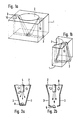
- Fig. 1 shows the lower end of the funnel, namely the expanding jaw itself.
- the funnel 2 is carried out in a housing 1.
- the bottom exit of the funnel is a passage that is smaller than the smallest grain. Through this A cut is made in the funnel, in the cutting plane of which the expanding jaw 3 is effective.
- the expanding jaw 3 is so wide that it opens a gap in the lower funnel part in the open state, which is larger than the largest grain.
- the expanding jaw 3 is rotatably mounted about the pivot point 10.
- FIG. 3 In order to rule out these incorrect assignments with certainty, only one expanding jaw 3a is provided according to FIG. 3.
- This one expanding jaw 3a is actuated by a slide 5 which is guided through the funnel.
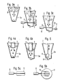
- This slide 5 is fork-shaped or in the form of a plate with corresponding air passage openings.
- This slide 5 it is important that the distance between the individual tines is chosen so that the grains cannot fall through. Furthermore, the distance between the external tines and the subsequent funnel wall must also be kept so small that no grains can fall through here either.
- This slide is retracted in the idle state and retracted so far that its tine ends are flush with the wall of the funnel. d. H. that the tines do not protrude into the interior of the funnel. In this state, the expanding jaw is also closed.
- the slide 5 is guided through the funnel by means of a drive 6 until it meets the opposite expanding jaws and this z. B. pushes so far outwards against a spring 7 that the opening which now arises lets the grain lying below drop out. During this phase, however, the slider seals off the space for the grains. so that falling grains remain on the slide. If the slide is then retracted by its drive 6, the expanding jaw closes and the retracted slide clears the way for the grains, which are now thrown upwards again by the excess pressure of air in the closed state of the expanding jaw, except for one Grain trying to close the through hole. With this arrangement, the drop height of the grains can be significantly reduced to decrease their downward travel and increase the speed of deposit.
- the expansion jaw 3a can be opened and closed by a drive 8 provided specifically for it.
- the slide 5 only runs after the expanding jaws 3a without touching it itself, the gap between the tine end and the expanding jaws being kept so small that the grains cannot fall through here either.
- the blow pipe 4 itself can also take on the task of the aforementioned slide valve. For this purpose, it is necessary that the blow tube is inserted into the funnel so that it can be raised and lowered. In its normal position according to FIG. 4a, there is a gap between the blow pipe end and the funnel wall, large enough to let the grains fall through. By blowing in the air, the grains are driven upwards again except for one that closes the opening at the bottom. If you now lower the blowpipe 4, and so far into the funnel that the gap between the blowpipe end and the funnel wall is smaller than the smallest grain, the floating grains are prevented from falling into the lower region. Now the expanding jaws 3a or the expanding jaws 3 can be opened at the same time, so that the grain lying below falls out. If the blow pipe 4 is guided upwards again, the process begins again.
- an ejector 11 can also be provided, which provides for or accelerates the downward ejection of the grains when the expanding jaw is open.
- This ejector 11 can be passed through the blowpipe and can be provided with its own drive or, in the cases in which the blowpipe can be raised and lowered, can be connected directly to it.
- a star can also be provided, which is arranged on the side of the funnel in such a way that it is rotated into the funnel like a wheel and leads rhythmically through an arm through the funnel from bottom to top, to the same extent as the expanding jaws opens and closes.
- the ejector can also be arranged as a stamp so that it pushes out the lower grain in the open state of the expanding jaw and at the same time in this position prevents the remaining grains from reaching the lower part of the funnel.
- the drive form for the control of the blowpipe as well as for the control of the slide or ejector are arbitrary, they can serve hydraulic, pneumatic or electrical control, and a mechanical cam can also be provided.
- the drive control is expediently made time-dependent, that is to say that the opening of the expanding jaw is carried out quickly, whereas its closing is delayed in time in order to achieve that the gap below is kept open a little longer in order to tear down the grains in suspension more quickly as a result .
- the slide is pulled away faster so that the opening downward is also released more by the slide than the final closing of the expanding jaw.
- this control must be provided so that the grains only reach the lower end of the funnel when the expanding jaw is fully closed again. This can also be achieved by an additional hole, which is opened and closed rhythmically with the aid of a flap control and which opens with a delay when the expanding jaw closes.
Landscapes
- Life Sciences & Earth Sciences (AREA)
- Soil Sciences (AREA)
- Environmental Sciences (AREA)
- Filling Or Emptying Of Bunkers, Hoppers, And Tanks (AREA)
- Combined Means For Separation Of Solids (AREA)
- Sowing (AREA)
- Apparatuses For Bulk Treatment Of Fruits And Vegetables And Apparatuses For Preparing Feeds (AREA)
- Control And Other Processes For Unpacking Of Materials (AREA)
- Drying Of Solid Materials (AREA)
- Processing Of Solid Wastes (AREA)
- Pretreatment Of Seeds And Plants (AREA)
- Disintegrating Or Milling (AREA)
- Threshing Machine Elements (AREA)
- Cereal-Derived Products (AREA)
- Noodles (AREA)
Priority Applications (1)
| Application Number | Priority Date | Filing Date | Title |
|---|---|---|---|
| AT82106990T ATE24370T1 (de) | 1981-08-10 | 1982-08-03 | Vorrichtung zum vereinzeln und ablegen von koernigem gut. |
Applications Claiming Priority (2)
| Application Number | Priority Date | Filing Date | Title |
|---|---|---|---|
| DE19813131620 DE3131620A1 (de) | 1981-08-10 | 1981-08-10 | Vorrichtung zum vereinzeln und ablegen von koernigem gut |
| DE3131620 | 1981-08-10 |
Publications (2)
| Publication Number | Publication Date |
|---|---|
| EP0071954A1 EP0071954A1 (de) | 1983-02-16 |
| EP0071954B1 true EP0071954B1 (de) | 1986-12-30 |
Family
ID=6139017
Family Applications (1)
| Application Number | Title | Priority Date | Filing Date |
|---|---|---|---|
| EP82106990A Expired EP0071954B1 (de) | 1981-08-10 | 1982-08-03 | Vorrichtung zum Vereinzeln und Ablegen von körnigem Gut |
Country Status (11)
| Country | Link |
|---|---|
| US (1) | US4544082A (enExample) |
| EP (1) | EP0071954B1 (enExample) |
| JP (1) | JPS5847728A (enExample) |
| AT (1) | ATE24370T1 (enExample) |
| DE (2) | DE3131620A1 (enExample) |
| DK (1) | DK356882A (enExample) |
| ES (3) | ES274680Y (enExample) |
| GR (1) | GR77217B (enExample) |
| HU (1) | HUH2988A (enExample) |
| SU (1) | SU1213968A3 (enExample) |
| ZA (1) | ZA825741B (enExample) |
Families Citing this family (7)
| Publication number | Priority date | Publication date | Assignee | Title |
|---|---|---|---|---|
| DE3637530C1 (de) * | 1986-11-04 | 1988-03-31 | Karl-Heinz Paul | Verfahren und Vorrichtung zum Saeen von vereinzelten Samen in eine von einem Schar gezogene Furche |
| EP1655012A4 (en) * | 2003-07-31 | 2008-01-16 | Yuyama Mfg Co Ltd | DEVICE FOR DISPOSING MEDICAMENTS AND MEDICATION FILLING DEVICE |
| JP2010503045A (ja) * | 2006-09-12 | 2010-01-28 | ブライユ−オージー プロプライエタリー リミテッド | 自動点字インサータ |
| DE102007062967A1 (de) | 2007-12-21 | 2009-06-25 | Horsch Maschinen Gmbh | Vorrichtung und Verfahren zur pneumatischen Einzelkornförderung |
| ES2397903B2 (es) * | 2011-08-05 | 2014-03-24 | Kaparazoom Slu | Pizarra de escritura y dibujo para personas ciegas o con discapacidad visual |
| EP3659417B1 (de) * | 2018-11-27 | 2025-11-05 | Kverneland Group Soest GmbH | Verfahren und anordnung zum ausbringen von mehrkörnigen dosiermengen eines granulatartigen materials mittels einer landwirtschaftlichen maschine sowie verteilmaschine |
| US12201051B2 (en) * | 2021-12-17 | 2025-01-21 | Eden Concepts, Llc | Apparatus and method for seed germination and planting |
Family Cites Families (7)
| Publication number | Priority date | Publication date | Assignee | Title |
|---|---|---|---|---|
| FR1216140A (fr) * | 1959-02-10 | 1960-04-22 | Procédé et appareil pour la distribution continue de matériaux solides et de liquide, mêlés en proportions réglables | |
| US3214060A (en) * | 1961-06-09 | 1965-10-26 | Ibm | Apparatus for feeding minute articles |
| FR1313016A (fr) * | 1962-02-02 | 1962-12-21 | Appareil remplisseur pneumatique pour polystyrène expansé | |
| JPS4924384B1 (enExample) * | 1970-12-12 | 1974-06-22 | ||
| AT311705B (de) * | 1970-12-29 | 1973-11-26 | Becker Karl Masch | Vorrichtung zum Vereinzeln von Elementen aus einer Menge etwa gleichförmiger Elemente |
| US3770164A (en) * | 1972-04-18 | 1973-11-06 | Fmc Corp | Singulator for seeds or the like |
| DE2847514C2 (de) * | 1978-11-02 | 1987-02-26 | Karl Becker GmbH & Co KG Maschinenfabrik, 3525 Oberweser | Vorrichtung zum Vereinzeln und Ablegen von körnigem Gut |
-
1981
- 1981-08-10 DE DE19813131620 patent/DE3131620A1/de not_active Withdrawn
-
1982
- 1982-08-03 AT AT82106990T patent/ATE24370T1/de not_active IP Right Cessation
- 1982-08-03 EP EP82106990A patent/EP0071954B1/de not_active Expired
- 1982-08-03 DE DE8282106990T patent/DE3274784D1/de not_active Expired
- 1982-08-05 US US06/405,398 patent/US4544082A/en not_active Expired - Fee Related
- 1982-08-06 JP JP57136424A patent/JPS5847728A/ja active Pending
- 1982-08-09 SU SU823476928A patent/SU1213968A3/ru active
- 1982-08-09 ES ES1982274680U patent/ES274680Y/es not_active Expired
- 1982-08-09 HU HU822561A patent/HUH2988A/hu unknown
- 1982-08-09 ZA ZA825741A patent/ZA825741B/xx unknown
- 1982-08-09 DK DK356882A patent/DK356882A/da not_active Application Discontinuation
- 1982-08-09 GR GR68981A patent/GR77217B/el unknown
-
1984
- 1984-02-16 ES ES1984277586U patent/ES277586Y/es not_active Expired
- 1984-02-16 ES ES1984277587U patent/ES277587Y/es not_active Expired
Also Published As
| Publication number | Publication date |
|---|---|
| JPS5847728A (ja) | 1983-03-19 |
| ES274680Y (es) | 1984-12-16 |
| ES274680U (es) | 1984-05-01 |
| DE3131620A1 (de) | 1983-02-24 |
| ES277587U (es) | 1984-07-16 |
| US4544082A (en) | 1985-10-01 |
| ES277586U (es) | 1984-10-16 |
| ES277587Y (es) | 1985-02-01 |
| EP0071954A1 (de) | 1983-02-16 |
| HUH2988A (en) | 1985-08-28 |
| DK356882A (da) | 1983-02-11 |
| ZA825741B (en) | 1983-07-27 |
| ATE24370T1 (de) | 1987-01-15 |
| SU1213968A3 (ru) | 1986-02-23 |
| ES277586Y (es) | 1985-05-01 |
| GR77217B (enExample) | 1984-09-11 |
| DE3274784D1 (en) | 1987-02-05 |
Similar Documents
| Publication | Publication Date | Title |
|---|---|---|
| DE69921936T2 (de) | Induktorgerät für Behälter in pneumatischen Drillmaschinen | |
| EP1024878B1 (de) | Verfahren und vorrichtung zum reinigen eines staubabscheiders | |
| DE1932312A1 (de) | Vorrichtung zum pneumatischen Heraussichten von Tabakrippen aus einem Gemisch von Tabakblatteilen und Tabakrippen | |
| DE4306135A1 (de) | Saugbagger | |
| DE69312937T2 (de) | Verfahren und vorrichtung zum vacuum transport | |
| DE202008017748U1 (de) | Ausblasvorrichtung zum selektiven Ausblasen von Fördergutteilen aus einem Fördergutstrom und Sortiervorrichtung mit einer solchen Ausblasvorrichtung | |
| DE2847514C2 (de) | Vorrichtung zum Vereinzeln und Ablegen von körnigem Gut | |
| DE2643041B2 (de) | Vorrichtung zur Gewinnung von Mineralen an einem Gewässergrund | |
| EP0071954B1 (de) | Vorrichtung zum Vereinzeln und Ablegen von körnigem Gut | |
| DE2628811C2 (de) | Pneumatische Förderanlage für pulverförmige und körnige Güter | |
| DE2106134B2 (de) | Windsichter für Schnittabak | |
| DE1761924A1 (de) | Verfahren und Vorrichtung zum Entfernen von festen Teilchen,welche sich auf einer Flaeche mindestens eines poroesen Filterelementes angesammelt haben | |
| DE567267C (de) | Bunker | |
| CH647425A5 (de) | Vorrichtung zum sortieren von materialstroemen in sortierte teilstroeme. | |
| DE4008401A1 (de) | Verfahren und vorrichtung zum oeffnen von kunststoffbeuteln | |
| EP3704923A1 (de) | Anordnung für eine landwirtschaftliche sämaschine, verfahren zum vereinzeln von saatkörnern in einer anordnung für eine landwirtschaftliche sämaschine sowie sämaschine | |
| DE3318797C2 (de) | Zellenradschleuse | |
| DE102016116908A1 (de) | Sämaschine mit Vereinzelungsvorrichtung | |
| DE491563C (de) | Verfahren zur Abscheidung von Fremdkoerpern aus mit einem Luftstrom befoerdertem Gut | |
| DE2705040C2 (enExample) | ||
| DE2819705C2 (de) | Tabakaufnahmeeinheit für den Verteiler einer Zigarettenherstellungsmaschine | |
| DE2434354A1 (de) | Taschenfilter mit pulsierender gegenstromspuelung | |
| DE3428278A1 (de) | Vorrichtung fuer die emissionsfreie bzw. -arme beschickung von lagerbehaeltern mit staubenden schuettguetern | |
| EP0822141A1 (de) | Vertikale Schlauchbeutelmaschine und Verfahren zur Beschleunigung einer Produktportion in einer vertikalen Schlauchbeutelmaschine | |
| DE2636362A1 (de) | Verfahren und vorrichtung zum absondern auf pneumatischem wege von leichteren teilen aus einem schwerere teile enthaltenden teilchenstrom |
Legal Events
| Date | Code | Title | Description |
|---|---|---|---|
| PUAI | Public reference made under article 153(3) epc to a published international application that has entered the european phase |
Free format text: ORIGINAL CODE: 0009012 |
|
| AK | Designated contracting states |
Designated state(s): AT BE CH DE FR GB IT LI NL SE |
|
| 17P | Request for examination filed |
Effective date: 19830615 |
|
| GRAA | (expected) grant |
Free format text: ORIGINAL CODE: 0009210 |
|
| AK | Designated contracting states |
Kind code of ref document: B1 Designated state(s): AT BE CH DE FR GB IT LI NL SE |
|
| REF | Corresponds to: |
Ref document number: 24370 Country of ref document: AT Date of ref document: 19870115 Kind code of ref document: T |
|
| REF | Corresponds to: |
Ref document number: 3274784 Country of ref document: DE Date of ref document: 19870205 |
|
| ITF | It: translation for a ep patent filed | ||
| ET | Fr: translation filed | ||
| PGFP | Annual fee paid to national office [announced via postgrant information from national office to epo] |
Ref country code: NL Payment date: 19870831 Year of fee payment: 6 |
|
| PLBE | No opposition filed within time limit |
Free format text: ORIGINAL CODE: 0009261 |
|
| STAA | Information on the status of an ep patent application or granted ep patent |
Free format text: STATUS: NO OPPOSITION FILED WITHIN TIME LIMIT |
|
| 26N | No opposition filed | ||
| PG25 | Lapsed in a contracting state [announced via postgrant information from national office to epo] |
Ref country code: GB Effective date: 19890803 Ref country code: AT Effective date: 19890803 |
|
| PG25 | Lapsed in a contracting state [announced via postgrant information from national office to epo] |
Ref country code: SE Effective date: 19890804 |
|
| PG25 | Lapsed in a contracting state [announced via postgrant information from national office to epo] |
Ref country code: LI Effective date: 19890831 Ref country code: CH Effective date: 19890831 Ref country code: BE Effective date: 19890831 |
|
| BERE | Be: lapsed |
Owner name: KARL BECKER G.M.B.H. & CO K.G. MASCHINENFABRIK Effective date: 19890831 |
|
| PG25 | Lapsed in a contracting state [announced via postgrant information from national office to epo] |
Ref country code: NL Effective date: 19900301 |
|
| GBPC | Gb: european patent ceased through non-payment of renewal fee | ||
| NLV4 | Nl: lapsed or anulled due to non-payment of the annual fee | ||
| PG25 | Lapsed in a contracting state [announced via postgrant information from national office to epo] |
Ref country code: FR Effective date: 19900427 |
|
| REG | Reference to a national code |
Ref country code: CH Ref legal event code: PL |
|
| PG25 | Lapsed in a contracting state [announced via postgrant information from national office to epo] |
Ref country code: DE Effective date: 19900501 |
|
| REG | Reference to a national code |
Ref country code: FR Ref legal event code: ST |
|
| EUG | Se: european patent has lapsed |
Ref document number: 82106990.3 Effective date: 19900418 |