EP0071954B1 - Device for isolating and depositing granular products - Google Patents
Device for isolating and depositing granular products Download PDFInfo
- Publication number
- EP0071954B1 EP0071954B1 EP82106990A EP82106990A EP0071954B1 EP 0071954 B1 EP0071954 B1 EP 0071954B1 EP 82106990 A EP82106990 A EP 82106990A EP 82106990 A EP82106990 A EP 82106990A EP 0071954 B1 EP0071954 B1 EP 0071954B1
- Authority
- EP
- European Patent Office
- Prior art keywords
- funnel
- spreading
- grain
- jaw
- sliding element
- Prior art date
- Legal status (The legal status is an assumption and is not a legal conclusion. Google has not performed a legal analysis and makes no representation as to the accuracy of the status listed.)
- Expired
Links
Images
Classifications
-
- A—HUMAN NECESSITIES
- A01—AGRICULTURE; FORESTRY; ANIMAL HUSBANDRY; HUNTING; TRAPPING; FISHING
- A01C—PLANTING; SOWING; FERTILISING
- A01C7/00—Sowing
- A01C7/04—Single-grain seeders with or without suction devices
- A01C7/042—Single-grain seeders with or without suction devices using pneumatic means
Definitions
- the invention relates to a device for separating and depositing granular material, in particular seed, by introducing an air stream into a funnel, the funnel being provided for receiving the granular material and its lower part being formed by funnel-shaped spreading jaws, on the lower one At the end of a passage is introduced, which is smaller than the smallest grain in the unspread state (DE-A-2 847 514).
- the lower end of the funnel is formed by expanding jaws. These spreading jaws have a passage at the lower exit that is smaller than the smallest grain. To deposit the grains, the spreading jaws are opened and closed, depending on the placement speed and the driving speed of the pulling vehicle.
- the principle is based on the fact that the air flowing into the funnel first tries to flow out of the passage at the bottom. However, this passage is largely closed by a grain. This means that only a small airflow can sweep past this lower grain. This low air flow causes a vacuum below this one grain compared to the greater pressure present in the funnel itself. This creates a downward suction effect for the lower grain, which holds it in place at the funnel exit.
- the air flow acting in the funnel itself is deflected in the funnel because it cannot escape fully downwards and is led out again upwards. It is of course essential here how the air flow is introduced into the funnel.
- the object of the present invention is that the air flow is directed into the funnel in such a way that it once blows out all the excess grains from the funnel, and brings them to such a levitation height that the opening of the jaws with the resultant change in the air flow only causes one of the grains lying at the bottom to fall out and that the expanding jaw is already closed again before the other grains have fallen from above.
- the air flow is introduced vertically into the funnel.
- the constantly changing flow conditions depending on the opening and closing of the expanding jaw determine the further process of separating and depositing the grain.
- the air flow speed has to be brought to the right level. It has been shown that a small excess pressure in the funnel is sufficient to blow out the grains.
- the air flowing into the funnel is diverted and, as a result of the above funnel expansion , is also diverted upwards.
- the only resistance is the grains in the funnel, but they are torn out with the current upwards.
- the grains then float above the lower part of the funnel and now open the lower spreading jaw by an angle that is just large enough to allow the grain there to drop out, so the flow conditions change.
- a much larger proportion of the air flow is diverted downward by enlarging the passage opening.
- this can be used according to the invention. e.g. B. by introducing a mechanical lock through which the falling of the grains temporarily, d. H. is interrupted during the opening phase of the expanding jaw.
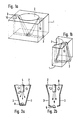
- Fig. 1 shows the lower end of the funnel, namely the expanding jaw itself.
- the funnel 2 is carried out in a housing 1.
- the bottom exit of the funnel is a passage that is smaller than the smallest grain. Through this A cut is made in the funnel, in the cutting plane of which the expanding jaw 3 is effective.
- the expanding jaw 3 is so wide that it opens a gap in the lower funnel part in the open state, which is larger than the largest grain.
- the expanding jaw 3 is rotatably mounted about the pivot point 10.
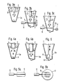
- FIG. 3 In order to rule out these incorrect assignments with certainty, only one expanding jaw 3a is provided according to FIG. 3.
- This one expanding jaw 3a is actuated by a slide 5 which is guided through the funnel.
- This slide 5 is fork-shaped or in the form of a plate with corresponding air passage openings.
- This slide 5 it is important that the distance between the individual tines is chosen so that the grains cannot fall through. Furthermore, the distance between the external tines and the subsequent funnel wall must also be kept so small that no grains can fall through here either.
- This slide is retracted in the idle state and retracted so far that its tine ends are flush with the wall of the funnel. d. H. that the tines do not protrude into the interior of the funnel. In this state, the expanding jaw is also closed.
- the slide 5 is guided through the funnel by means of a drive 6 until it meets the opposite expanding jaws and this z. B. pushes so far outwards against a spring 7 that the opening which now arises lets the grain lying below drop out. During this phase, however, the slider seals off the space for the grains. so that falling grains remain on the slide. If the slide is then retracted by its drive 6, the expanding jaw closes and the retracted slide clears the way for the grains, which are now thrown upwards again by the excess pressure of air in the closed state of the expanding jaw, except for one Grain trying to close the through hole. With this arrangement, the drop height of the grains can be significantly reduced to decrease their downward travel and increase the speed of deposit.
- the expansion jaw 3a can be opened and closed by a drive 8 provided specifically for it.
- the slide 5 only runs after the expanding jaws 3a without touching it itself, the gap between the tine end and the expanding jaws being kept so small that the grains cannot fall through here either.
- the blow pipe 4 itself can also take on the task of the aforementioned slide valve. For this purpose, it is necessary that the blow tube is inserted into the funnel so that it can be raised and lowered. In its normal position according to FIG. 4a, there is a gap between the blow pipe end and the funnel wall, large enough to let the grains fall through. By blowing in the air, the grains are driven upwards again except for one that closes the opening at the bottom. If you now lower the blowpipe 4, and so far into the funnel that the gap between the blowpipe end and the funnel wall is smaller than the smallest grain, the floating grains are prevented from falling into the lower region. Now the expanding jaws 3a or the expanding jaws 3 can be opened at the same time, so that the grain lying below falls out. If the blow pipe 4 is guided upwards again, the process begins again.
- an ejector 11 can also be provided, which provides for or accelerates the downward ejection of the grains when the expanding jaw is open.
- This ejector 11 can be passed through the blowpipe and can be provided with its own drive or, in the cases in which the blowpipe can be raised and lowered, can be connected directly to it.
- a star can also be provided, which is arranged on the side of the funnel in such a way that it is rotated into the funnel like a wheel and leads rhythmically through an arm through the funnel from bottom to top, to the same extent as the expanding jaws opens and closes.
- the ejector can also be arranged as a stamp so that it pushes out the lower grain in the open state of the expanding jaw and at the same time in this position prevents the remaining grains from reaching the lower part of the funnel.
- the drive form for the control of the blowpipe as well as for the control of the slide or ejector are arbitrary, they can serve hydraulic, pneumatic or electrical control, and a mechanical cam can also be provided.
- the drive control is expediently made time-dependent, that is to say that the opening of the expanding jaw is carried out quickly, whereas its closing is delayed in time in order to achieve that the gap below is kept open a little longer in order to tear down the grains in suspension more quickly as a result .
- the slide is pulled away faster so that the opening downward is also released more by the slide than the final closing of the expanding jaw.
- this control must be provided so that the grains only reach the lower end of the funnel when the expanding jaw is fully closed again. This can also be achieved by an additional hole, which is opened and closed rhythmically with the aid of a flap control and which opens with a delay when the expanding jaw closes.
Abstract
Description
Die Erfindung bezieht sich auf eine Vorrichtung zum Vereinzeln und Ablegen von körnigem Gut, insbesondere Saatgut, indem ein Luftstrom in einen Trichter eingeleitet wird, wobei der Trichter zur Aufnahme des körnigen Gutes vorgesehen ist und sein unterer Teil durch trichterförmige Spreizbacken gebildet ist, an deren unterem Ende ein Durchlaß eingebracht ist, der im ungespreizten Zustand kleiner als das kleinste Korn ist (DE-A-2 847 514).The invention relates to a device for separating and depositing granular material, in particular seed, by introducing an air stream into a funnel, the funnel being provided for receiving the granular material and its lower part being formed by funnel-shaped spreading jaws, on the lower one At the end of a passage is introduced, which is smaller than the smallest grain in the unspread state (DE-A-2 847 514).
Das untere Trichterende ist durch Spreizbacken gebildet. Diese Spreizbacken besitzen einen Durchlaß am unteren Ausgang, der kleiner als das kleinste Korn ist. Zur Ablage der Körner werden die Spreizbacken geöffnet und geschlossen und zwar abhängig von der Ablagegeschwindigkeit und von der Fahrgeschwindigkeit des ziehenden Fahrzeuges.The lower end of the funnel is formed by expanding jaws. These spreading jaws have a passage at the lower exit that is smaller than the smallest grain. To deposit the grains, the spreading jaws are opened and closed, depending on the placement speed and the driving speed of the pulling vehicle.
Das Prinzip beruht darauf, daß die in den Trichter einströmende Luft zunächst versucht, unten aus dem Durchlaß herauszuströmen. Dieser Durchlaß ist jedoch durch ein Korn größtenteils verschlossen. Somit kann auch nur ein geringer Luftstrom an diesem unteren Korn vorbeistreichen. Dieser geringe Luftstrom verursacht unterhalb dieses einen Kornes einen Unterdruck gegenüber dem größeren im Trichter selbst anstehenden Druck. Damit entsteht für das untere Korn eine nach unten gerichtete Sogwirkung, die es am Trichterausgang festhält. Der im Trichter selbst wirkende Luftstrom wird dagegen, da er nach unten nicht voll entweichen kann, im Trichter umgelenkt und wieder nach oben herausgeführt. Hierbei ist natürlich von wesentlicher Bedeutung, wie der Luftstrom in den Trichter eingeleitet wird.The principle is based on the fact that the air flowing into the funnel first tries to flow out of the passage at the bottom. However, this passage is largely closed by a grain. This means that only a small airflow can sweep past this lower grain. This low air flow causes a vacuum below this one grain compared to the greater pressure present in the funnel itself. This creates a downward suction effect for the lower grain, which holds it in place at the funnel exit. The air flow acting in the funnel itself, on the other hand, is deflected in the funnel because it cannot escape fully downwards and is led out again upwards. It is of course essential here how the air flow is introduced into the funnel.
Die Aufgabe der vorliegenden Erfindung besteht darin, daß der Luftstrom so in den Trichter geleitet wird, daß er einmal alle überzähligen Körner aus dem Trichter herausbläst, und diese in eine solche Schwebehöhe bringt, daß das Öffnen des Spreibackens mit der dadurch bedingten Veränderung hinsichtlich der Luftströmung nur ein Herausfallen des einen unten liegenden Kornes veranlaßt und daß der Spreizbacken bereits wieder geschlossen ist, bevor die übrigen Körner von oben heruntergefallen sind. Um höhere Ablagegeschwindigkeiten zu erzielen, ist es erforderlich, daß der Trichter wieder bis unten voll gefüllt ist, wenn der Spreizbacken geschlossen hat. Das bedeutet aber, daß das Herunterfallen der Körner nach dem Öffnen des Spreizbackens gesteuert werden muß.The object of the present invention is that the air flow is directed into the funnel in such a way that it once blows out all the excess grains from the funnel, and brings them to such a levitation height that the opening of the jaws with the resultant change in the air flow only causes one of the grains lying at the bottom to fall out and that the expanding jaw is already closed again before the other grains have fallen from above. In order to achieve higher placement speeds, it is necessary that the funnel is filled to the bottom again when the expanding jaw has closed. However, this means that the dropping of the grains must be controlled after opening the expanding jaw.
Erfindungsgemäß geschieht dieses durch die in Anspruch 1 angegebenen Merkmale.According to the invention, this is done by the features specified in claim 1.
Der Luftstrom wird senkrecht in den Trichter eingeleitet. Die ständig sich ändernden Strömungsverhältnisse in Abhängigkeit vom Öffnen und Schließen des Spreizbackens bestimmen den weiteren Ablauf des Vereinzelns und Ablegen des Kornes. Hierbei ist noch die Luftstromgeschwindigkeit auf das richtige Maß zu bringen. Es hat sich gezeigt, daß bereits ein kleiner Überdruck im Trichter ausreicht, um die Körner herauszublasen. Die in den Trichter einströmende Luft wird umgeleitet und in Folge der obigen Trichte- raufweitung auch nach oben wieder herausgeleitet. Als einziger Widerstand sind hierbei die im Trichter befindlichen Körner anzusehen, diese werden jedoch mit dem Strom nach oben herausgerissen. Die Körner schweben dann oberhalb des unteren Trichterteiles und öffnet jetzt der untere Spreizbacken um einen Winkel, der gerade groß genug ist, um das eine daselbst befindliche Korn herausfallen zu lassen, so tritt eine Änderung der Strömungsverhältnisse ein. Es wird durch die Vergrößerung der Durchlaßöffnung ein wesentlich größerer Anteil des Luftstromes nach unten abgeleitet. Damit ist der im Trichter zuvor nach oben umgelenkte Luftstrom nicht mehr in der Lage, die Körner oberhalb des Trichters in der Schwebe zu halten, diese fallen herunter. Gleichzeitig erfährt das eine abzulegende Korn eine geringe Beschleunigung, die seinen Austritt durch die Trichteröffnung etwas schneller vonstatten gehen läßt. Da aber gleichzeitig die Trichteröffnung vergrößert ist, ist der Beschleunigungseffekt sehr gering und übt keinerlei Nachteile auf die Ablage dieses Kornes aus. Sobald das eine Korn den Trichterausgang passiert hat, wird der Spreizbacken wieder geschlossen und der Vorgang beginnt von neuem. Dadurch, daß der obere Teil des Trichters in der Höhe ein Vielfaches von dem Weg beträgt, den das Einzelkorn in der Backenöffnung zurücklegen muß, ist gewährleistet, daß während des Öffnungsvorganges kein anderes Korn die Backenöffnung erreicht, bevor der Spreizbacken wieder geschlossen hat. Die Schwebehöhen der überschüssigen Körner im Trichter ist bei geschlossenem Backen aber noch höher, da diese tatsächlich aus dem Trichterteil herausgeblasen werden, in dem der Spreizbacken wirksam ist. Im geöffnetem Zustand des Spreizbackens entsteht nur in Folge des größeren Luftaustrittes nach unten für die im Schwebezustand befindlichen Körner eine Sogwirkung, die ihr Herabfallen beschleunigt.The air flow is introduced vertically into the funnel. The constantly changing flow conditions depending on the opening and closing of the expanding jaw determine the further process of separating and depositing the grain. Here the air flow speed has to be brought to the right level. It has been shown that a small excess pressure in the funnel is sufficient to blow out the grains. The air flowing into the funnel is diverted and, as a result of the above funnel expansion , is also diverted upwards. The only resistance is the grains in the funnel, but they are torn out with the current upwards. The grains then float above the lower part of the funnel and now open the lower spreading jaw by an angle that is just large enough to allow the grain there to drop out, so the flow conditions change. A much larger proportion of the air flow is diverted downward by enlarging the passage opening. This means that the air flow previously deflected upwards in the funnel is no longer able to hold the grains in suspension above the funnel, and they fall down. At the same time, the grain to be deposited experiences a slight acceleration, which allows it to emerge somewhat faster through the funnel opening. However, since the hopper opening is enlarged at the same time, the acceleration effect is very small and has no disadvantages for depositing this grain. As soon as the one grain has passed the hopper exit, the expanding jaw is closed again and the process begins again. The fact that the upper part of the funnel is several times higher than the distance that the individual grain has to travel in the jaw opening ensures that no other grain reaches the jaw opening during the opening process before the expanding jaw has closed again. The floating heights of the excess grains in the funnel are even higher when the jaws are closed, since they are actually blown out of the funnel part in which the expanding jaw is effective. In the open state of the expanding jaws, only as a result of the larger air outlet downward, a suction effect for the grains which are in suspension, which accelerates their falling down.
Zur Erzielung höherer Ablagegeschwindigkeiten läßt sich dieses erfindungsgemäß ausnutzen. z. B. durch Einbringen einer mechanischen Sperre, durch die das Herabfallen der Körner vorübergehend, d. h. während der Phase der Öffnung des Spreizbackens, unterbrochen wird.To achieve higher storage speeds, this can be used according to the invention. e.g. B. by introducing a mechanical lock through which the falling of the grains temporarily, d. H. is interrupted during the opening phase of the expanding jaw.
Anhand von Zeichnungsbeispielen sei die Erfindung näher erläutert :
- Figuren 1a und 1b geben perspektivisch die Wirkungsweise des Spreizbackens wieder und
die
- FIGS. 1a and 1b show in perspective the mode of operation of the expanding jaw and
Figures 2 to 5 represent schematically the operation of expanding jaws and sliders.
Fig. 1 zeigt das untere Ende des Trichters, nämlich den Spreizbacken selbst. In einem Ge-- häuse 1 ist der Trichter 2 durchgeführt. Der untere Ausgang des Trichters ist ein Durchlaß, der kleiner ist als das kleinste Korn. Durch diesen Trichter ist ein Schnitt gelegt, in dessen Schnittebene der Spreizbacken 3 wirksam ist. Der Spreizbacken 3 ist so breit ausgeführt, daß er im geöffnetem Zustand einen Spalt im unteren Trichterteil freigibt, der größer ist als das größte Korn. Der Spreizbacken 3 ist um den Drehpunkt 10 drehbar gelagert.Fig. 1 shows the lower end of the funnel, namely the expanding jaw itself. The
Die Wirkungsweise ist nun folgende :
- In den
Trichter 3 ragt ein Blasrohr 4, durch dieses Blasrohr wird Luft in den Trichter bis in den unteren Spreizbackenteil eingeblasen. Diese eingeblasene Luft erzeugt im Trichter einen Überdruck und am unteren Ende des Trichters unterhalb des Durchlasses einen leichten Unterdruck. Dadurch wird ein Korn jeweils an der Öffnung festgesaugt, während die anderen durch den Überdruck nach oben geblasen werden. Sie erreichen hierbei eine Schwebehöhe, die außerhalb des Spreizbackenbereiches liegt. Öffnen jetzt dieSpreizbacken 3, so wird eine Öffnung freigegeben, die das unten liegende Korn durchfallen läßt. Gleichzeitig verändern sich die Verhältnisse im Innern des Trichters, die in der Schwebe gehaltenen Körner werden heruntergerissen. Der Ausstoß des unteren Kornes wird beschleunigt, da durch das Blasrohr noch Druckluft nach unten austritt. Die Fallhöhe der in Schwebe gehaltenen Körner ist so hoch zu bemessen, daß ihr Weg, den sie nach unten zurücklegen, größer ist als der Weg, den der Spreizbacken zum Öffnen und Schließen benötigt.
- A blower tube 4 projects into the
funnel 3, through which blower tube air is blown into the funnel up to the lower expansion jaw part. This blown air creates an overpressure in the funnel and a slight underpressure at the lower end of the funnel below the passage. As a result, one grain is sucked into the opening, while the others are blown upwards by the excess pressure. You will reach a hover height that is outside the range of the expanding jaws. Now open the expandingjaws 3, an opening is released, which allows the grain below to fall through. At the same time, the conditions inside the funnel change, the grains suspended are torn down. The output of the lower grain is accelerated because compressed air still exits through the blow tube. The drop height of the grains held in suspension is to be dimensioned so high that their path downward is greater than the path that the expanding jaw needs to open and close.
Diese Anordnung läßt nur bestimmte Ablagegeschwindigkeiten zu. Diese sind bedingt durch die Fallhöhe der schwebenden Körner. Sollen größere Ablegegeschwindigkeiten gefahren werden, muß die Fallhöhe verringert werden. Hierbei besteht dann die Gefahr, daß bereits Körner das untere Ende des Spreizbackens erreicht haben, ehe dieser wieder ganz geschlossen ist.This arrangement allows only certain filing speeds. These are due to the drop height of the floating grains. The fall height must be reduced if higher laying speeds are to be used. There is then a risk that grains have already reached the lower end of the expanding jaw before it is completely closed again.
Um diese Fehlbelegungen mit Sicherheit auszuschließen, wird gemäß Fig. 3 nur ein Spreizbacken 3a vorgesehen. Dieser eine Spreizbacken 3a wird durch einen Schieber 5 betätigt, der durch den Trichter hindurchgeführt ist. Dieser Schieber 5 ist gabelförmig ausgeführt oder in Form einer Platte mit entsprechenden Luftdurchtrittsöffnungen. Bei dem Schieber 5 ist wichtig, daß der Abstand der einzelnen Zinken so gewählt ist, daß die Körner nicht hindurchfallen können. Ferner ist der Abstand zwischen den außen liegenden Zinken und der anschließenden Trichterwand ebenfalls so klein zu halten daß auch hier keine Körner durchfallen können. Dieser Schieber ist im Ruhezustand zurückgezogen und zwar so weit zurückgezogen, daß seine Zinkenenden mit der Wandung des Trichters abschließen. d. h. daß die Zinken nicht in den Innenraum des Trichters ragen. In diesem Zustand ist auch der Spreizbacken geschlossen. Die durch die eingeblasene Luft im Schwebezustand gehaltenen Körner befinden sich oberhalb der Schieberebene. Soll jetzt der Spreizbacken 3a betätigt werden, so wird der Schieber 5 mittels eines Antriebes 6 durch den Trichter hindurchgeführt, bis er auf den gegenüberliegenden Spreizbacken trifft und diesen z. B. gegen eine Feder 7 so weit nach außen schiebt, daß die nunmehr entstehende Öffnung das unten liegende Korn herausfallen läßt. Während dieser Phase riegelt der Schieber jedoch den Raum nach oben für die Körner ab. so daß herunterfallende Körner auf dem Schieber liegenbleiben. Wird der Schieber anschließend durch seinen Antrieb 6 zurückgezogen, so schließt der Spreizbacken und der eingefahrene Schieber gibt den Weg für die Körner nach unten frei, die im geschlossenen Zustand des Spreizbackens nunmehr wieder durch den Überdruck an Luft nach oben geschleudert werden, bis auf das eine Korn, das versucht, die Durchgangsbohrung zu schließen. Bei dieser Anordnung kann die Fallhöhe der Körner wesentlich verringert werden, damit ihr Weg nach unten verringert werden und die Ablagegeschwindigkeit gesteigert werden.In order to rule out these incorrect assignments with certainty, only one expanding
Im Bedarfsfall kann das Öffnen und Schließen des Spreizbackens 3a durch einen eigens für ihn vorgesehenen Antrieb 8 geschehen. In diesem Falle läuft der Schieber 5 dem Spreizbacken 3a nur nach ohne ihn selbst zu berühren, wobei der Spaltzwischen Zinkenende und Spreizbacken entsprechend so klein zu halten ist, daß die Körner auch hier nicht durchfallen können.If necessary, the
Die Aufgabe des zuvor erwähnten Schiebers kann auch das Blasrohr 4 selbst übernehmen. Hierzu ist es erforderlich, daß das Blasrohr heb-und senkbar in den Trichter eingebracht ist. In seiner Normalstellung gemäß Fig. 4a ergibt sich zwischen Blasrohrende und Trichterwand ein Spalt, groß genug, um die Körner hindurchfallen zu lassen. Durch das Einblasen der Luft werden die Körner entsprechend wieder nach oben getrieben bis auf eines, das unten die Öffnung verschließt. Senkt man jetzt das Blasrohr 4 ab, und zwar soweit in den Trichter hinein, daß der Spalt zwischen Blasrohrende und Trichterwand kleiner ist als das kleinste Korn, dann wird ein Herabfallen der schwebenden Körner in den unteren Bereich vermieden. Nunmehr kann gleichzeitig der Spreizbacken 3a oder die Spreizbacken 3 geöffnet werden, so daß das unten liegende Korn herausfällt. Wird das Blasrohr 4 wieder nach oben geführt, beginnt der Vorgang wieder von neuem.The blow pipe 4 itself can also take on the task of the aforementioned slide valve. For this purpose, it is necessary that the blow tube is inserted into the funnel so that it can be raised and lowered. In its normal position according to FIG. 4a, there is a gap between the blow pipe end and the funnel wall, large enough to let the grains fall through. By blowing in the air, the grains are driven upwards again except for one that closes the opening at the bottom. If you now lower the blowpipe 4, and so far into the funnel that the gap between the blowpipe end and the funnel wall is smaller than the smallest grain, the floating grains are prevented from falling into the lower region. Now the expanding
Im Bedarfsfall kann ferner ein Auswerfer 11 vorgesehen sein, der den Ausstoß der Körner nach unten bei geöffnetem Spreizbacken vorsieht oder beschleunigt. Dieser Auswerfer 11 kann durch das Blasrohr durchgeführt werden und mit eigenem Antrieb versehen sein oder in den Fällen, in denen das Blasrohr heb- und senkbar angeordnet ist, direkt mit ihm verbunden sein.If necessary, an
Anstatt des Schiebers kann auch ein Stern vorgesehen werden, der seitlich an dem Trichter so angeordnet ist, daß er wie ein Rad in den Trichter hineingedreht wird und dabei rhythmisch über einen Arm von unten nach oben durch den Trichter führt, in dem Maße wie der Spreizbacken öffnet und schließt. Es kann auch der Auswerfer so als Stempel angeordnet werden, daß er das untere Korn im geöffnetem Zustand des Spreizbackens herausdrückt und gleichzeitig in dieser Stellung aber die übrigen Körner daran hindert, den unteren Bereich des Trichters zu erreichen. Die Antriebsform sowohl für die Steuerung des Blasrohres als auch für die Steuerung des Schiebers oder Auswerfers sind beliebig, sie können hydraulischer, pneumatischer oder elektrischer Ansteuerung dienen, auch ist ein mechanischer Nocken vorsehbar. Die Antriebssteuerung wird jedoch zweckmäßig zeitabhängig gemacht, d. h. daß der Öffnungsvorgang des Spreizbackens schnell vollzogen wird, wohingegen sein Schließen zeitlich verzögert wird, um so zu erreichen, daß der Spalt unten etwas länger offen gehalten wird, um die in der Schwebe befindlichen Körner dadurch schneller herunterzureißen. Bei der Anordnung mit einem Schieber wird hierbei der Schieber schneller weggezogen, so daß die Öffnung nach unten auch durch den Schieber mehr freigegeben ist, als das endgültige Schließen des Spreizbackens erfolgt. Selbstverständlich ist diese Steuerung so vorzusehen, daß die Körner das untere Ende des Trichters erst dann erreichen, wenn der Spreizbacken wieder voll geschlossen ist. Dieses läßt sich auch durch eine zusätzliche Bohrung erzielen, die mit Hilfe einer Klappensteuerung rhythmisch geöffnet und geschlossen wird und die beim Schließen des Spreizbackens verzögert aufmacht.Instead of the pusher, a star can also be provided, which is arranged on the side of the funnel in such a way that it is rotated into the funnel like a wheel and leads rhythmically through an arm through the funnel from bottom to top, to the same extent as the expanding jaws opens and closes. The ejector can also be arranged as a stamp so that it pushes out the lower grain in the open state of the expanding jaw and at the same time in this position prevents the remaining grains from reaching the lower part of the funnel. The drive form for the control of the blowpipe as well as for the control of the slide or ejector are arbitrary, they can serve hydraulic, pneumatic or electrical control, and a mechanical cam can also be provided. However, the drive control is expediently made time-dependent, that is to say that the opening of the expanding jaw is carried out quickly, whereas its closing is delayed in time in order to achieve that the gap below is kept open a little longer in order to tear down the grains in suspension more quickly as a result . In the case of the arrangement with a slide, the slide is pulled away faster so that the opening downward is also released more by the slide than the final closing of the expanding jaw. Of course, this control must be provided so that the grains only reach the lower end of the funnel when the expanding jaw is fully closed again. This can also be achieved by an additional hole, which is opened and closed rhythmically with the aid of a flap control and which opens with a delay when the expanding jaw closes.
Claims (14)
Priority Applications (1)
| Application Number | Priority Date | Filing Date | Title |
|---|---|---|---|
| AT82106990T ATE24370T1 (en) | 1981-08-10 | 1982-08-03 | DEVICE FOR SEPARATING AND DEPOSITING GRAINY GOOD. |
Applications Claiming Priority (2)
| Application Number | Priority Date | Filing Date | Title |
|---|---|---|---|
| DE3131620 | 1981-08-10 | ||
| DE19813131620 DE3131620A1 (en) | 1981-08-10 | 1981-08-10 | DEVICE FOR SEPARATING AND STORING GRAINY GOODS |
Publications (2)
| Publication Number | Publication Date |
|---|---|
| EP0071954A1 EP0071954A1 (en) | 1983-02-16 |
| EP0071954B1 true EP0071954B1 (en) | 1986-12-30 |
Family
ID=6139017
Family Applications (1)
| Application Number | Title | Priority Date | Filing Date |
|---|---|---|---|
| EP82106990A Expired EP0071954B1 (en) | 1981-08-10 | 1982-08-03 | Device for isolating and depositing granular products |
Country Status (11)
| Country | Link |
|---|---|
| US (1) | US4544082A (en) |
| EP (1) | EP0071954B1 (en) |
| JP (1) | JPS5847728A (en) |
| AT (1) | ATE24370T1 (en) |
| DE (2) | DE3131620A1 (en) |
| DK (1) | DK356882A (en) |
| ES (3) | ES274680Y (en) |
| GR (1) | GR77217B (en) |
| HU (1) | HUH2988A (en) |
| SU (1) | SU1213968A3 (en) |
| ZA (1) | ZA825741B (en) |
Families Citing this family (6)
| Publication number | Priority date | Publication date | Assignee | Title |
|---|---|---|---|---|
| DE3637530C1 (en) * | 1986-11-04 | 1988-03-31 | Karl-Heinz Paul | Method and device for sowing individual seeds into a furrow drawn by a flock |
| US7823748B2 (en) * | 2003-07-31 | 2010-11-02 | Yuyama Mfg. Co., Ltd. | Drug dispenser and drug filling apparatus incorporating the same |
| AU2007295947B2 (en) * | 2006-09-12 | 2011-01-20 | Braille-Oz Pty Ltd | Automated Braille inserter |
| DE102007062967A1 (en) | 2007-12-21 | 2009-06-25 | Horsch Maschinen Gmbh | Pneumatic single grain conveyor for e.g. corn-, Soya or beet spreading machine, has separating device decoupled from sowing plough, and pneumatic delivery pipe opening laterally and arranged lateral to perforated disc |
| ES2397903B2 (en) * | 2011-08-05 | 2014-03-24 | Kaparazoom Slu | SLATE OF WRITING AND DRAWING FOR BLIND PERSONS OR WITH VISUAL DISABILITIES |
| EP3659417A1 (en) * | 2018-11-27 | 2020-06-03 | Kverneland AS | Method and device for the delivery of multi-grain dosage quantities of a granulate material by means of an agricultural machine |
Family Cites Families (7)
| Publication number | Priority date | Publication date | Assignee | Title |
|---|---|---|---|---|
| FR1216140A (en) * | 1959-02-10 | 1960-04-22 | Method and apparatus for the continuous distribution of solid and liquid materials, mixed in adjustable proportions | |
| US3214060A (en) * | 1961-06-09 | 1965-10-26 | Ibm | Apparatus for feeding minute articles |
| FR1313016A (en) * | 1962-02-02 | 1962-12-21 | Pneumatic filling device for expanded polystyrene | |
| JPS4924384B1 (en) * | 1970-12-12 | 1974-06-22 | ||
| AT311705B (en) * | 1970-12-29 | 1973-11-26 | Becker Karl Masch | Device for separating elements from a set of approximately uniform elements |
| US3770164A (en) * | 1972-04-18 | 1973-11-06 | Fmc Corp | Singulator for seeds or the like |
| DE2847514A1 (en) * | 1978-11-02 | 1980-05-14 | Becker Karl Masch | DEVICE FOR SEPARATING AND STORING GRAINY GOODS |
-
1981
- 1981-08-10 DE DE19813131620 patent/DE3131620A1/en not_active Withdrawn
-
1982
- 1982-08-03 AT AT82106990T patent/ATE24370T1/en not_active IP Right Cessation
- 1982-08-03 DE DE8282106990T patent/DE3274784D1/en not_active Expired
- 1982-08-03 EP EP82106990A patent/EP0071954B1/en not_active Expired
- 1982-08-05 US US06/405,398 patent/US4544082A/en not_active Expired - Fee Related
- 1982-08-06 JP JP57136424A patent/JPS5847728A/en active Pending
- 1982-08-09 GR GR68981A patent/GR77217B/el unknown
- 1982-08-09 DK DK356882A patent/DK356882A/en not_active Application Discontinuation
- 1982-08-09 ES ES1982274680U patent/ES274680Y/en not_active Expired
- 1982-08-09 SU SU823476928A patent/SU1213968A3/en active
- 1982-08-09 ZA ZA825741A patent/ZA825741B/en unknown
- 1982-08-09 HU HU822561A patent/HUH2988A/en unknown
-
1984
- 1984-02-16 ES ES1984277586U patent/ES277586Y/en not_active Expired
- 1984-02-16 ES ES1984277587U patent/ES277587Y/en not_active Expired
Also Published As
| Publication number | Publication date |
|---|---|
| DE3274784D1 (en) | 1987-02-05 |
| DE3131620A1 (en) | 1983-02-24 |
| ATE24370T1 (en) | 1987-01-15 |
| HUH2988A (en) | 1985-08-28 |
| DK356882A (en) | 1983-02-11 |
| ZA825741B (en) | 1983-07-27 |
| US4544082A (en) | 1985-10-01 |
| ES277587U (en) | 1984-07-16 |
| ES277586Y (en) | 1985-05-01 |
| GR77217B (en) | 1984-09-11 |
| SU1213968A3 (en) | 1986-02-23 |
| ES277587Y (en) | 1985-02-01 |
| ES274680U (en) | 1984-05-01 |
| JPS5847728A (en) | 1983-03-19 |
| ES277586U (en) | 1984-10-16 |
| EP0071954A1 (en) | 1983-02-16 |
| ES274680Y (en) | 1984-12-16 |
Similar Documents
| Publication | Publication Date | Title |
|---|---|---|
| DE69921936T2 (en) | Inductor device for containers in pneumatic seed drills | |
| DE3003919C2 (en) | ||
| DE1932312A1 (en) | Device for pneumatic sifting out of tobacco stems from a mixture of tobacco leaf parts and tobacco stems | |
| DE4306135A1 (en) | Suction dredger | |
| DE102007006133A1 (en) | Emptying magazine and method for emptying shaft trays filled with rod-shaped products | |
| DE2643041B2 (en) | Device for the extraction of minerals on the bottom of a body of water | |
| WO1999020370A1 (en) | Process and device for cleaning a dust separator | |
| DE2628811C2 (en) | Pneumatic conveyor system for powdery and granular goods | |
| EP0071954B1 (en) | Device for isolating and depositing granular products | |
| CH643982A5 (en) | DEVICE AND METHOD FOR SEPARATING AND DEPOSITING SEEDS, IN PARTICULAR SEEDS. | |
| DE2900605A1 (en) | DEVICE FOR PICKING UP OBJECTS IN THE FORM OF A RANDOM LOT OF PILE AND FOR SERIAL DELIVERY OF THE SAME IN THE FORM OF A SINGLE ROW | |
| DE2106134B2 (en) | Wind sifter for cut tobacco | |
| DE1761924A1 (en) | Method and device for removing solid particles which have accumulated on a surface of at least one porous filter element | |
| DE567267C (en) | bunker | |
| DE2158338C3 (en) | Method and device for cleaning filter cells | |
| DE102016116908A1 (en) | Seeder with separating device | |
| DE4008401A1 (en) | METHOD AND DEVICE FOR OPENING PLASTIC BAGS | |
| DE2638934B2 (en) | Device for removing incorrect packs | |
| DE3318797C2 (en) | Rotary valve | |
| DE491563C (en) | Process for the separation of foreign bodies from material conveyed with an air stream | |
| DE2705040C2 (en) | ||
| EP3704923A1 (en) | Assembly for an agricultural seeding machine, method for separating seed grains in an arrangement for an agricultural seeding machine and seeding machine | |
| DE2819705C2 (en) | Tobacco receiving unit for the distributor of a cigarette manufacturing machine | |
| DE3428278A1 (en) | DEVICE FOR THE EMISSION-FREE OR -LOW LOADING OF STORAGE CONTAINERS WITH DUSTING SHUBLE GOODS | |
| EP0822141A1 (en) | Vertical form-fill-seal machine and method of accelerating a product charge in a vertical form-fill-seal machine |
Legal Events
| Date | Code | Title | Description |
|---|---|---|---|
| PUAI | Public reference made under article 153(3) epc to a published international application that has entered the european phase |
Free format text: ORIGINAL CODE: 0009012 |
|
| AK | Designated contracting states |
Designated state(s): AT BE CH DE FR GB IT LI NL SE |
|
| 17P | Request for examination filed |
Effective date: 19830615 |
|
| GRAA | (expected) grant |
Free format text: ORIGINAL CODE: 0009210 |
|
| AK | Designated contracting states |
Kind code of ref document: B1 Designated state(s): AT BE CH DE FR GB IT LI NL SE |
|
| REF | Corresponds to: |
Ref document number: 24370 Country of ref document: AT Date of ref document: 19870115 Kind code of ref document: T |
|
| REF | Corresponds to: |
Ref document number: 3274784 Country of ref document: DE Date of ref document: 19870205 |
|
| ITF | It: translation for a ep patent filed |
Owner name: STUDIO JAUMANN |
|
| ET | Fr: translation filed | ||
| PGFP | Annual fee paid to national office [announced via postgrant information from national office to epo] |
Ref country code: NL Payment date: 19870831 Year of fee payment: 6 |
|
| PLBE | No opposition filed within time limit |
Free format text: ORIGINAL CODE: 0009261 |
|
| STAA | Information on the status of an ep patent application or granted ep patent |
Free format text: STATUS: NO OPPOSITION FILED WITHIN TIME LIMIT |
|
| 26N | No opposition filed | ||
| PG25 | Lapsed in a contracting state [announced via postgrant information from national office to epo] |
Ref country code: GB Effective date: 19890803 Ref country code: AT Effective date: 19890803 |
|
| PG25 | Lapsed in a contracting state [announced via postgrant information from national office to epo] |
Ref country code: SE Effective date: 19890804 |
|
| PG25 | Lapsed in a contracting state [announced via postgrant information from national office to epo] |
Ref country code: LI Effective date: 19890831 Ref country code: CH Effective date: 19890831 Ref country code: BE Effective date: 19890831 |
|
| BERE | Be: lapsed |
Owner name: KARL BECKER G.M.B.H. & CO K.G. MASCHINENFABRIK Effective date: 19890831 |
|
| PG25 | Lapsed in a contracting state [announced via postgrant information from national office to epo] |
Ref country code: NL Effective date: 19900301 |
|
| GBPC | Gb: european patent ceased through non-payment of renewal fee | ||
| NLV4 | Nl: lapsed or anulled due to non-payment of the annual fee | ||
| PG25 | Lapsed in a contracting state [announced via postgrant information from national office to epo] |
Ref country code: FR Effective date: 19900427 |
|
| REG | Reference to a national code |
Ref country code: CH Ref legal event code: PL |
|
| PG25 | Lapsed in a contracting state [announced via postgrant information from national office to epo] |
Ref country code: DE Effective date: 19900501 |
|
| REG | Reference to a national code |
Ref country code: FR Ref legal event code: ST |
|
| EUG | Se: european patent has lapsed |
Ref document number: 82106990.3 Effective date: 19900418 |