EP0071183A2 - Düsenkopf - Google Patents
Düsenkopf Download PDFInfo
- Publication number
- EP0071183A2 EP0071183A2 EP82106597A EP82106597A EP0071183A2 EP 0071183 A2 EP0071183 A2 EP 0071183A2 EP 82106597 A EP82106597 A EP 82106597A EP 82106597 A EP82106597 A EP 82106597A EP 0071183 A2 EP0071183 A2 EP 0071183A2
- Authority
- EP
- European Patent Office
- Prior art keywords
- extruder
- filling
- nozzle
- melt
- hollow body
- Prior art date
- Legal status (The legal status is an assumption and is not a legal conclusion. Google has not performed a legal analysis and makes no representation as to the accuracy of the status listed.)
- Granted
Links
Images
Classifications
-
- A—HUMAN NECESSITIES
- A23—FOODS OR FOODSTUFFS; TREATMENT THEREOF, NOT COVERED BY OTHER CLASSES
- A23G—COCOA; COCOA PRODUCTS, e.g. CHOCOLATE; SUBSTITUTES FOR COCOA OR COCOA PRODUCTS; CONFECTIONERY; CHEWING GUM; ICE-CREAM; PREPARATION THEREOF
- A23G3/00—Sweetmeats; Confectionery; Marzipan; Coated or filled products
- A23G3/02—Apparatus specially adapted for manufacture or treatment of sweetmeats or confectionery; Accessories therefor
- A23G3/20—Apparatus for coating or filling sweetmeats or confectionery
- A23G3/2007—Manufacture of filled articles, composite articles, multi-layered articles
- A23G3/2015—Manufacture of filled articles, composite articles, multi-layered articles the material being shaped at least partially by a die; Extrusion of filled or multi-layered cross-sections or plates, optionally with the associated cutting device
-
- A—HUMAN NECESSITIES
- A23—FOODS OR FOODSTUFFS; TREATMENT THEREOF, NOT COVERED BY OTHER CLASSES
- A23G—COCOA; COCOA PRODUCTS, e.g. CHOCOLATE; SUBSTITUTES FOR COCOA OR COCOA PRODUCTS; CONFECTIONERY; CHEWING GUM; ICE-CREAM; PREPARATION THEREOF
- A23G3/00—Sweetmeats; Confectionery; Marzipan; Coated or filled products
- A23G3/02—Apparatus specially adapted for manufacture or treatment of sweetmeats or confectionery; Accessories therefor
- A23G3/20—Apparatus for coating or filling sweetmeats or confectionery
- A23G3/2007—Manufacture of filled articles, composite articles, multi-layered articles
- A23G3/2069—Moulding or shaping of cellular or expanded articles
-
- A—HUMAN NECESSITIES
- A23—FOODS OR FOODSTUFFS; TREATMENT THEREOF, NOT COVERED BY OTHER CLASSES
- A23P—SHAPING OR WORKING OF FOODSTUFFS, NOT FULLY COVERED BY A SINGLE OTHER SUBCLASS
- A23P30/00—Shaping or working of foodstuffs characterised by the process or apparatus
- A23P30/20—Extruding
- A23P30/25—Co-extrusion of different foodstuffs
-
- A—HUMAN NECESSITIES
- A23—FOODS OR FOODSTUFFS; TREATMENT THEREOF, NOT COVERED BY OTHER CLASSES
- A23P—SHAPING OR WORKING OF FOODSTUFFS, NOT FULLY COVERED BY A SINGLE OTHER SUBCLASS
- A23P30/00—Shaping or working of foodstuffs characterised by the process or apparatus
- A23P30/30—Puffing or expanding
- A23P30/32—Puffing or expanding by pressure release, e.g. explosion puffing; by vacuum treatment
- A23P30/34—Puffing or expanding by pressure release, e.g. explosion puffing; by vacuum treatment by extrusion-expansion
-
- B—PERFORMING OPERATIONS; TRANSPORTING
- B30—PRESSES
- B30B—PRESSES IN GENERAL
- B30B11/00—Presses specially adapted for forming shaped articles from material in particulate or plastic state, e.g. briquetting presses, tabletting presses
- B30B11/22—Extrusion presses; Dies therefor
- B30B11/221—Extrusion presses; Dies therefor extrusion dies
Definitions
- the invention relates to a nozzle head for a cooking extruder, the extruder nozzle axis of which runs perpendicular to the extruder screw axis and a filling tube extends through the extruder nozzle. Furthermore, the invention relates to a method for producing a light, expanded, center-filled food product using this nozzle head and to the product itself.
- Such a nozzle head for a cooking extruder is known from US Pat. No. 3,615,675.
- a nozzle head of this type for a cooking extruder With a nozzle head of this type for a cooking extruder, a crispy expanding envelope body which is designed like a crispbread is produced continuously, and this envelope body is completely filled with an edible mass in one operation.
- the known cooking extruder has a screw. If a moist flour-containing material is passed through the extruder, pressure builds up. The material becomes flowable, a semi-plastic dough forms in which the water remains in a liquid state due to the pressures and temperatures generated. When the dough comes out of the extruder nozzle and is subjected to a reduced pressure, for example an atmospheric pressure, the liquid evaporates and a porous, cellular body is formed.
- the melt flow path in front of the outlet nozzle is deflected by 90 °, and a filling tube extends through the outlet nozzle, and this filling tube extends beyond the outlet nozzle.
- a filling tube extends through the outlet nozzle, and this filling tube extends beyond the outlet nozzle.
- the melt emerging from the extruder screw is in direct contact with the cold filling tube in the nozzle, and this causes difficulties.
- the filling compound which usually contains fat, can be heated too much so that it becomes liquid and then damages the hollow body produced.
- the melt can be cooled through the cold filling tube to a temperature below 100 ° C. immediately before expansion, so that the liquid no longer evaporates when it emerges and no porous cell body is formed.
- the expanded envelope solidifies very quickly and therefore sticks very easily to the expanding filling tube.
- the invention is based on the object of designing the cooking extruder in such a way that, on the one hand, the filling compound is not heated and, on the other hand, the melt is not cooled when it emerges and in any case has a temperature which is above 100.degree.
- the steam generated in the envelope should not get into the end product.
- this object is achieved in that the filling tube is surrounded by a mandrel which forms an annular space, that is to say a sleeve, which separates this filling tube from the space guiding the melt and which extends to the outlet opening of the extruder nozzle.
- the filling tube can be isolated from the melt, so that the filling compound cannot melt in the filling tube and, on the other hand, the melt maintains the required temperature even when it emerges from the extruder nozzle in order to allow the liquid to evaporate.
- the expanded envelope which consists of a honeycomb structure of gelatinized starch mass, is therefore easily dissolved and deformed when it comes into contact with water.
- Vapor must not accumulate in the expanded envelope, because otherwise the envelope will be partially softened by the resulting condensate and the filling compound can escape at these points. For this reason, the annular space between the filling pipe and the mandrel is connected to a vacuum pump, which can be used to extract vapors that form during expansion. In order to form a good enveloping body, the space which guides the melt and which surrounds the mandrel must be filled correctly. Therefore, the melt emerging from the extruder screw is divided into two partial flows, the upstream being deflected by 90 0 around the mandrel are brought together from the extruder die. This allows the flow velocity and the pressure of the melt to be distributed evenly around the circumference of the mandrel.
- the flow paths of different lengths and different mechanical and thermal loads on the melt only lead to an incomplete confluence of the two partial streams.
- this creates flow seams or thin spots in the extruded casing from which the filling compound can escape.
- a wiping thread is installed in the flow path of the melt upstream of the extruder nozzle. The wiping thread creates a tangential deflection of the melt stream, which blurs the flow seams.
- the wiping thread surrounds the mandrel.
- An exchangeable ring can advantageously surround the wiping thread to form an annular space.
- the width of the annular gap between the wiping thread and the metal ring can be adjusted so that the melt guidance can be optimally adapted to the rheological properties of the melt.
- the feed of the extruder melt and the feed of the filling compound are completely separate from one another, so that metering of both components is possible without mutual influence on temperature.
- the filling compound is fed into the solidified casing at a distance of about 40 cm from the extruder nozzle, calculated through the filling pipe.
- the filled solidified tube is divided into individual bars by a squeezing device, which are then dried.
- the extruder nozzle can be equipped with a thread, so that there is a storage space with variable volume when screwed into the nozzle head.
- the storage space can be reduced or enlarged by turning the extruder nozzle. This allows optimal adaptation to the flow properties of the substance to be processed during the extrusion, so that a closed, uniformly expanded tube emerges from the extruder.
- Another advantage of the plastic-coated filler pipe is the better sliding properties, so that the expanded casing does not stick to the filler pipe.
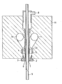
- the drawing shows a section through the die head of the cooking extruder, this section being perpendicular to the screw axis.
- the screw section of the cooking extruder is not shown.
- the nozzle head 11 has two melt feed lines 1 a and 1, the melt emerging from the extruder screw perpendicular to the plane of the drawing and being fed to the nozzle head 11.
- the partial streams 1 and 1a are deflected downward to the extruder nozzle 3 by 90 °.
- a filling tube 9 extends through the extruder nozzle 3, and this filling tube guides the filling compound.
- the filling tube 9 opens out at a distance of about 40 cm from the extruder nozzle 3.
- the filling tube 9 is surrounded by a mandrel 2, which is tubular, in such a way that this mandrel 2 isolates the filling tube from the melt upstream of the outlet opening 6.
- This insulation keeps the filling tube 9 cool and, on the other hand, prevents the melt in the outlet opening of the extruder nozzle 3 from cooling down in such a way that the liquid no longer evaporates.
- An annular space 7 is located between the filling pipe 9 and the mandrel 2, and this annular space 7 is connected to a steam suction vacuum pump 8.
- a wiping thread 4 is provided in the flow path of the melt.
- the wiping thread 4 expediently surrounds the mandrel 2. The purpose of the wiping thread 4 is to tangentially deflect the melt flow and thus to blur any seams.
- an interchangeable ring 5 is arranged in the flow path of the melt, which forms an annular gap with the wiping thread, and this ring gap can be adjusted by metal rings 5 of different thicknesses in order to optimally adapt the flow path to the rheological properties of the melt.
- the process according to the invention for producing a light, expanded, middle-filled food product whereby superatmospheric pressures and a temperature above the boiling point of the liquid for a given tannin are generated in a mass of food material containing a liquid, and this material by a generally circular opening leads to a zone of said lower pressure and thereby expands the material by evaporation of the liquid therein and leads the expanded material as a long hollow body through a cooling zone which is considerably longer than the outer diameter of the hollow body and heat from the hollow body into the cooling zone dissipates and a filler in injected into the center of the hollow body after this hollow body has expanded and is sufficiently coherent to hang unsupported without breaking and the hollow body is then optionally cut and baked, the filling tube (9) used to fill the hollow body is separated from it by one an annular space (7) forming mandrel (or sleeve) (2) is surrounded, which separates this filling tube (9) from the melt-guiding space (10) and which extends to the outlet opening (6) of the ex
- the mass of edible material containing a liquid is preferably a moist floury material and the liquid is usually water which may be added as such or may come from milk or other edible liquids such as juices.
- the mass of edible material is preferably in the extruder at a temperature of about 100 to 150 ° C and under a pressure of about 150 to 250 atmospheres. When pressing out of the extruder nozzle, expansion then takes place, the extent of which can be adjusted in a manner known per se by the pressure and temperature of the mass in the extruder. According to a particularly preferred embodiment, the released steam is sucked out of the annular space (7) between the filling pipe (9) and the sleeve (2).
- An extrusion mixture is produced from the following components:
- This mixture is now processed in a cooking extruder equipped with the die head described in the application.
- a uniform, expanded pipe with a cross section of approx. 15 mm now emerges from this nozzle.
- the temperature at the nozzle is 125 ° C and the pressure is approx. 190 bar.
- a commercially available nougat mass is fed through the filling pipe by means of a high-pressure pump. About 40 cm. After leaving the extruder nozzle, the expanded tube is filled with the nougat mass.
- the filled pipe is then cut into pieces approx. 10 cm long by a cutting device. These pieces are dried in a belt dryer at 70 ° C to a final water content of 4%. The result is light bars filled with nougat with an envelope / filling ratio of 1: 2.
- Frilled chips products can be produced using the same process.
- a cheese cream is used as a filling and is made by mixing
- the filled tube is lightly pressed flat with the help of two rollers and then cut into pieces with a length of 1.5 cm using a cutting device.
Landscapes
- Engineering & Computer Science (AREA)
- Life Sciences & Earth Sciences (AREA)
- Chemical & Material Sciences (AREA)
- Food Science & Technology (AREA)
- Polymers & Plastics (AREA)
- Mechanical Engineering (AREA)
- Manufacturing & Machinery (AREA)
- Extrusion Moulding Of Plastics Or The Like (AREA)
- Formation And Processing Of Food Products (AREA)
Abstract
Description
- Die Erfindung betrifft einen Düsenkopf für einen Kochextruder, dessen Extruderdüsenachse senkrecht zur Extruderschneckenachse verläuft und durch dessen Extruderdüse hindurch sich ein Füllrohr erstreckt. Weiterhin betrifft die Erfindung ein Verfahren zur Herstellung eines leichten expandierten in der Mitte gefüllten Nahrungsmittelproduktes unter Verwendung dieses Düsenkopfes und das Produkt selbst.
- Ein derartiger Düsenkopf für einen Kochextruder ist aus der US-PS 3 615 675 bekannt. Mit einem derartigen Düsenkopf für einen Kochextruder wird kontinuierlich ein röscher expandierender Hüllkörper, der knäckebrotähnlich ausgebildet ist, hergestellt, und dieser Hüllkörper wird mit einer essbaren Masse vollständig in einem Arbeitsgang gefüllt. Der bekannte Kochextruder weist eine Schnecke auf. Wird ein feuchtes mehlhaltiges Material durch den Extruder hindurchgeführt, kommt es zu einem Druckaufbau. Das Material wird fliessbar, es bildet sich eine halbplastische Teigmasse, in der das Wasser durch die erzeugten Drücke und Temperaturen in flüssigem Zustand verbleibt. Wenn die Teigmasse aus der Extruderdüse austritt und einem verminderten Druck, beispielsweise einem Atmosphärendruck, ausgesetzt wird, so verdampft die Flüssigkeit und es entsteht ein poröser, zellförmiger Körper. Bei dem bekannten Kochextruder wird der Schmelzfliessweg vor der Austrittsdüse um 90° umgelenkt, und durch die Austrittsdüse hindurch erstreckt sich ein Füllrohr, und dieses Füllrohr erstreckt sich über die Austrittsdüse hinweg. Dadurch wird in der Austrittsdüse ein Ringraum gebildet, und die Schmelze tritt als Hohlkörper aus, der dann gefüllt werden kann.
- Bei dem bekannten Kochextruder befindet sich die aus der Extruderschnecke ausgetretene Schmelze in einem direkten Kontakt mit dem kalten Füllrohr in der Düse, und dies bringt Schwierigkeiten mit sich. Zu einem kann die Füllmasse, die meistens fetthaltig ist, zu stark erwärmt werden, so daß sie flüssig wird und dann den hergestellten Hohlkörper beschädigt. Zum anderen kann unmittelbar vor dem Expandieren die Schmelze durch das kalte Füllrohr auf eine Temperatur unter 100 C abgekühlt werden, so daß beim Austreten die Flüssigkeit nicht mehr verdampft und kein poröser Zellkörper gebildet wird. Ausserdem erstarrt der expandierte Hüllkörper dadurch sehr schnell und bleibt deshalb sehr leicht an dem sich erweiternden Füllrohr haften.
- Der Erfindung liegt die Aufgabe zu Grunde, den Kochextruder derart auszubilden, daß einerseits die Füllmasse nicht erhitzt wird und andererseits die Schmelze beim Austritt nicht gekühlt wird und auf alle Fälle eine Temperatur aufweist, die über 100°C liegt. Ausserdem soll der im Hüllkörper entstehende Dampf nicht in das Endprodukt gelangen.
- Erfindungsgemäß wird diese Aufgabe dadurch gelöst, daß das Füllrohr von einen mit diesem einen Ringraum bildenden Dorn, also einer Hülse, umgeben ist, der dieses Füllrohr von dem die Schmelze führenden Raum trennt und der sich bis zur Austrittsöffnung der Extruderdüse erstreckt. Durch diese Ausbildung kann das Füllrohr von der Schmelze isoliert werden, so daß einmal die Füllmasse im Füllrohr nicht schmelzen kann und zum anderen die Schmelze selbst beim Austreten aus der Extruderdüse die erforderliche Temperatur behält, um ein Verdampfen der Flüssigkeit zu ermöglichen. Beim Hochdruck-Extrusionsverfahren verdampft aus dem Extrudat im Moment des Austritts aus der Düse ca. 8% Wasser. Der expandierte Hüllkörper, der aus einer Wabenstruktur von gelatinierter Stärkemasse besteht, wird beim Zusammentreffen mit Wasser deshalb sehr leicht angelöst und deformiert.
- Im expandierten Hüllkörper darf es nicht zu Ansammlungen von Dampf kommen, weil sonst durch das entstehende Kondensat der Hüllkörper punktuell aufgeweicht wird und die Füllmasse an diesen Stellen austreten kann. Deshalb ist der Ringraum zwischen dem Füllrohr und dem Dorn mit einer Vakuumpumpe verbunden, über die sich beim Expandieren bildende Dämpfe abgesaugt werden können. Um einen guten Hüllkörper zu bilden, muß der die Schmelze führende Raum, der den Dorn umgibt, in richtiger Weise gefüllt werden. Deshalb wird die aus der Extruderschnecke austretende Schmelze in zwei Teilströme aufgeteilt, die unter Umlenkung um 900 um den Dorn herum stromauf von der Extruderdüse zusammengeführt sind. Hierdurch können sich Strömungsgeschwindigkeit und der Druck der Schmelze gleichmäßig um den Umfang des Dorns verteilen. An den Stellen, an denen die beiden Schmelzteilströme zusammenfließen, kommt es auf Grund unterschiedlich langer Fließwege, sowie unterschiedlicher mechanischer und thermischer Belastungen der Schmelze nur zu einem unvollständigen Zusammenfließen der beiden Teilströme. Beim Austrag aus der Extruderdüse entstehen dadurch Fließnähte oder Dünnstellen im extrudierten Hüllkörper, an denen die Füllmasse austreten kann. Um der Ausbildung von Fließnähten entgegenzuwirken, wird in den Fließweg der Schmelze stromauf der Extruderdüse ein Verwischgewinde eingebaut. Das Verwischgewinde erzeugt eine Umlenkung des Schmelzstromes in tangentialer wodurch die Fließnähte verwischt werden.
- Besonders vorteilhaft ist es, wenn das Verwischgewinde den Dorn umgibt.
- Mit Vorteil kann ein-austauschbarer Ring unter Bildung eines Ringraumes das Verwischgewinde umgeben. Durch das Einsetzen unterschiedlich dicker Ringe kann die Breite des Ringspaltes zwischen dem Verwischgewinde und dem Metallring eingestellt werden, so daß die Schmelzführung den rheologischen Eigenschaften der Schmelze optimal angepaßt werden kann.
- Die Zuführung der Extruderschmelze und die Zuführung der Füllmasse sind vollständig voneinander getrennt, so daß eine Dosierung beider Komponenten ohne gegenseitige Temperaturbeeinflussung möglich ist. Die Füllmasse wird in einem Abstand von etwa 40 cm von der Extruderdüse aus gerechnet durch das Füllrohr in den erstarrten Hüllkörper eingespeist.
- Die gefüllte erstarrte Röhre wird durch eine Abquetschvorrichtung in einzelne Riegel unterteilt, die anschließend getrocknet werden.
- Die Extruderdüse kann mit einem Gewinde ausgestattet sein, so dass sich beim Einschrauben in den Düsenkopf ein Stauraum mit variablem Volumen ergibt. Durch das Verdrehen der Extruderdüse kann der Stauraum verkleinert bzw. vergrössert werden. Damit kann während der Extrusion eine optimale Anpassung an die Fliesseigenschaft der zu verarbeitenden Substanz erfolgen, so dass ein geschlossenes, gleichmässig expandiertes Rohr aus dem Extruder austritt.
- Als vorteilhaft hat sich die Verwendung eines mit Kunststoff (Teflon) überzogenen Stahlrohrs erwiesen, da sich dadurch eine bessere thermische Trennung in der kalten Füllmasse und der noch heissen Füllkörper ergibt.
- Ein weiterer Vorteil-des kunststoffbeschichteten Füllrohres ist die bessere Gleitfähigkeit, so dass ein Haften des expandierten Hüllkörpers auf dem Füllrohr sicher verhindert wird.
- Ein Ausführungsbeispiel der Erfindung soll in der folgenden Beschreibung unter Bezugnahme auf die Zeichnung erläutert werden.
- Die Zeichnung stellt einen Schnitt durch den Düsenkopf des Kochextruders dar, wobei dieser Schnitt senkrecht zur Schneckenachse verläuft. Der Schneckenabschnitt des Kochextruders ist nicht dargestellt.
- Der Düsenkopf 11 weist zwei Schmelzzuleitungen 1a und 1 auf, wobei die Schmelze senkrecht zur Zeichenebene aus der Extruderschnecke austritt und dem Düsenkopf 11 zugeführt wird. Die Teilströme 1 und 1a werden zur Extruderdüse 3 hin um 90° nach unten umgelenkt.
- Durch die Extruderdüse 3 hindurch erstreckt sich ein Füllrohr 9, und dieses Füllrohr leitet die Füllmasse. Das Füllrohr 9 mündet in einem Abstand von etwa 40 cm von der Extruderdüse 3.
- In dem die Schmelze führenden Raum 10 wird das Füllrohr 9 von einem Dorn 2, der rohrförmig ausgebildet ist, derart umgeben, daß dieser Dorn 2 stromauf der Austrittsöffnung 6 das Füllrohr von der Schmelze isoliert.
- Diese Isolierung hält das Füllrohr 9 kühl und verhindert zum anderen, daß sich die Schmelze in der Austrittsöffnung der Extruderdüse 3 derart abkühlt, daß keine Verdampfung der Flüssigkeit mehr stattfindet.
- Zwischen dem Füllrohr 9 und dem Dorn 2 befindet sich ein Ringraum 7, und dieser Ringraum 7 steht mit einer Dampfabsaugungsvakuumpumpe 8 in Verbindung.
- Wenn die Schmelze aus der Extruderdüse3 austritt und expandiert, entstehen große Dampfmengen, die den rohrförmigen porösen Körper aufweichen könnten. Dies wird durch das Absaugen des entstehenden Dampfes sicher verhindert.
- Die Aufteilung in zwei Teilströme 1 und 1a ist erforderlich, um den Ringraum um den Dorn 2 herum in ausreichender Weise mit Schmelze zu füllen. Um eine Nahtbildung am Hüllkörper zu verhindern, die zu Schwachstellen führen könnte, ist im Fließweg der Schmelze ein Verwischgewinde 4 vorgesehen. Zweckmäßigerweise umgibt das Verwischgewinde 4 den Dorn 2. Der Zweck des Verwischgewindes 4 ist es, den Schmelzestrom tangential umzulenken und somit evtl. Nahtstellen zu verwischen.
- In der Höhe des Verwischgewindes ist im Fließweg der Schmelze ein austauschbarer Ring 5 angeordnet, der mit dem Verwischgewinde einen Ringspalt bildet,und durch unterschiedlich dicke Metallringe 5 kann dieser Ringspalt eingestellt werden, um den Fließweg den rheologischen Eigenschaften der Schmelze optimal anzupassen.
- Das erfindungsgemäße Verfahren zur Herstellung eines leichten, expandierten in der Mitte gefüllten Nahrungsmittelproduktes, wobei man in einer Masse von Nahrungsmittelmaterial, die eine Flüssigkeit enthält, überatmosphärische Drücke und eine Temperatur über dem Siedepunkt der Flüssigkeit bei einem gegebenen gerbgeren erzeugt und dieses Material durch eine im allgemeinen kreisförmige Öffnung zu einer Zone des besagten geringeren Druckes führt und dadurch das Material durch Verdampfen der Flüssigkeit darin expandiert und das expandierte Material als langen Hohlkörper durch eine Kühlzone führt, die eine beträchtlich größere Länge hat als der Außendurchmesser des Hohlkörpers und Wärme vom Hohlkörper in die Kühlzone abführt und ein Füllmaterial in die Mitte des Hohlkörpers injiziert, nachdem dieser Hohlkörper expandiert und ausreichend zusammenhängend ist um ungestützt ohne Brechen zu hängen und der Hohlkörper dann gegebenenfalls in Segmente geschnitten und gebacken wird, besteht darin, daß das zum Füllen des Hohlkörpers benutzte Füllrohr (9) von einem mit diesem einen Ringraum (7) bildenen Dorn (bzw. Hülse) (2) umgeben ist, der dieses Füllrohr (9) von dem die Schmelze führenden Raum (10) trennt und der sich bis zur Austrittsöffnung (6) der Extruderdüse (3) erstreckt.
- Die Masse von eßbarem Material, die eine Flüssigkeit enthält, ist vorzugsweise ein feuchtes mehlhaltiges Material und die Flüssigkeit ist überlicherweise Wasser, das als solches zugegeben oder zum Beispiel von Milch oder anderen eßbaren Flüssigkeiten wie Säften, stammen kann. Die Masse von eßbarem Material befindet sich vorzugsweise im Extruder bei einer Temperatur von etwa 100 bis 150 °C und unter einem Druck von etwa 150 bis 250 Atmosphären. Beim Auspressen aus der Extruderdüse findet dann eine Expansion statt, deren Ausmaß in an sich bekannter Weise durch Druck und Temperatur der Masse im Extruder eingestellt werden kann. Gemäß einer besonders bevorzugten Ausführungsform wird der freigesetzte Dampf aus dem Ringraum (7) zwischen Füllrohr (9) und Hülse (2) abgesaugt.
- Die folgenden Beispiele erläutern die Erfindung:
- Es wird eine Extrusionsmischung aus folgenden Bestandteilen hergestellt:
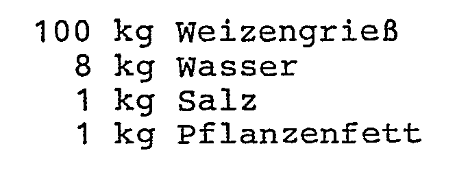
- Diese Mischung wird nun in einem Kochextruder verarbeitet, der mit dem in der Anmeldung beschriebenen Düsenkopf ausgestattet ist. An dieser Düse tritt nun ein gleichmäßiges expandiertes Rohr mit ca. 15 mm Querschnitt aus. Die Temperatur an der Düse beträgt 125 °C der Druck ca. 190 bar.
- Durch das Füllrohr wird mittels einer Hochdruckpumpe eine handelsübliche Nougatmasse zugeführt. Etwa 40 cm .nach dem Austritt aus der Extruderdüse wird das expandierte Rohr mit der Nougatmasse gefüllt.
- Anschließend wird das gefüllte Rohr durch eine Schneidvorrichtung in ca. 10 cm lange Stücke unterteilt. Diese Stücke werden in einem Bandtrockner bei 70 °C bis auf einen Endwassergehalt von 4 % getrocknet. Das Ergebnis sind leichte mit Nougat gefüllte Riegel mit einem Hüllkörper/Füllmasseverhältnis von 1:2.
- Nach dem gleichen Verfahren lassen sich Produkte vom Typ "gefüllte Chips" herstellen.
- Dazu wird eine Extrusionsmischung folgender Zusammensetzung verwendet:
-

- Als Füllung dient eine Käsecreme die hergestellt wird durch das Mischen von

- Das gefüllte Rohr wird mit Hilfe von zwei Walzen leicht flachgepresst und anschließend mit einer Schneidevorrichtung in Stücke von 1,5 cm Länge geschnitten.
- Das Ergebnis sind kissenförmige "Chips" mit einer Käsefüllung.
Claims (11)
Applications Claiming Priority (2)
| Application Number | Priority Date | Filing Date | Title |
|---|---|---|---|
| DE3129947A DE3129947C2 (de) | 1981-07-29 | 1981-07-29 | Düsenkopf für einen Kochextruder |
| DE3129947 | 1981-07-29 |
Publications (3)
| Publication Number | Publication Date |
|---|---|
| EP0071183A2 true EP0071183A2 (de) | 1983-02-09 |
| EP0071183A3 EP0071183A3 (en) | 1983-05-18 |
| EP0071183B1 EP0071183B1 (de) | 1986-03-05 |
Family
ID=6138021
Family Applications (1)
| Application Number | Title | Priority Date | Filing Date |
|---|---|---|---|
| EP82106597A Expired EP0071183B1 (de) | 1981-07-29 | 1982-07-21 | Düsenkopf |
Country Status (3)
| Country | Link |
|---|---|
| US (1) | US4486163A (de) |
| EP (1) | EP0071183B1 (de) |
| DE (1) | DE3129947C2 (de) |
Cited By (8)
| Publication number | Priority date | Publication date | Assignee | Title |
|---|---|---|---|---|
| FR2565521A1 (fr) * | 1984-06-08 | 1985-12-13 | Clextral | Filiere d'extrusion de produits alimentaires fourres |
| EP0126570A3 (en) * | 1983-05-13 | 1986-01-22 | Warner-Lambert Company | A powder filled chewing gum piece |
| GB2162788A (en) * | 1984-08-09 | 1986-02-12 | Vincent Processes Limited | Co-extrusion die assembly for a cooker extruder |
| EP0173982A1 (de) * | 1984-09-07 | 1986-03-12 | Convent Knabber-Gebäck GmbH & Co. KG | Kochextruder |
| US4618499A (en) * | 1984-02-15 | 1986-10-21 | United Biscuits (Uk) Limited | Methods for making filled extruded food products |
| EP0218992A3 (en) * | 1985-10-10 | 1989-09-13 | Heinz Schaaf | Cooking extruder |
| EP0218993A3 (en) * | 1985-10-10 | 1989-09-27 | Heinz Schaaf | Cooking extruder |
| EP2016830A1 (de) * | 2007-07-20 | 2009-01-21 | Albert Handtmann Maschinenfabrik GmbH & Co. KG | Vorrichtung und Verfahren zum Herstellen von Würsten |
Families Citing this family (17)
| Publication number | Priority date | Publication date | Assignee | Title |
|---|---|---|---|---|
| ATE26906T1 (de) * | 1984-07-30 | 1987-05-15 | Frisco Findus Ag | Herstellung eines nahrungsmittels. |
| US4748031A (en) * | 1985-04-17 | 1988-05-31 | Nabisco Brands, Inc. | Method of triple co-extruding bakeable products |
| US4715803A (en) * | 1985-04-17 | 1987-12-29 | Nabisco Brands, Inc. | Triple co-extruder |
| US4888192A (en) * | 1986-03-05 | 1989-12-19 | Nabisco Brands, Inc. | Method for extrusion of baked goods |
| US4698004A (en) * | 1986-03-05 | 1987-10-06 | Nabisco Brands, Inc. | Nozzle for extrusion |
| DE3617413A1 (de) * | 1986-05-23 | 1987-11-26 | Vemag Verdener Masch App | Verfahren und vorrichtung zum herstellen gefuellter massen |
| US4928592A (en) * | 1989-05-15 | 1990-05-29 | Continental Baking Company | Dual injection cake filler apparatus |
| US20050214421A1 (en) * | 2004-03-24 | 2005-09-29 | Kraft Foods Holdings, Inc. | Method and apparatus for extruding filled doughs |
| WO2007044628A1 (en) * | 2005-10-07 | 2007-04-19 | Wm. Wrigley Jr. Company | Apparatus and method for making multiple component confectionery product |
| AU2006337627A1 (en) * | 2006-02-07 | 2007-08-16 | Wm. Wrigley Jr. Company | Apparatus and method for preparing a multiple phase confectionery product |
| US9247752B2 (en) * | 2006-08-07 | 2016-02-02 | Kellogg Company | Apparatus and method for curled extrudate |
| US7883735B2 (en) * | 2006-08-07 | 2011-02-08 | Kellogg Company | Apparatus and method for curled extrudate |
| US20080095899A1 (en) * | 2006-10-13 | 2008-04-24 | Wm. Wrigley Jr. Company | Method and apparatus for producing a multiple phase, confectionery article |
| EP2062480A1 (de) * | 2007-11-21 | 2009-05-27 | Nestec S.A. | Koextrusionsdüsenbaugruppe, Verfahren zur Herstellung eines koextrudierten Nahrungsmittels und koextrudiertes Nahrungsmittel |
| KR102834173B1 (ko) * | 2021-06-24 | 2025-07-15 | 주식회사 비페코 | 갑각류 연육조직 대체육 제조방법 |
| CN115211450B (zh) * | 2022-07-12 | 2024-02-02 | 蔡煜邦 | 一种含乳酸菌的焙烤能量棒的加工方法 |
| CN115153075B (zh) * | 2022-07-12 | 2023-02-28 | 欧麦香(福建)食品有限公司 | 一种可进行乳酸菌添加的能量棒成型设备 |
Family Cites Families (11)
| Publication number | Priority date | Publication date | Assignee | Title |
|---|---|---|---|---|
| US3615675A (en) * | 1967-07-31 | 1971-10-26 | Frito Lay Inc | Method for making center-filled puffed food product |
| GB1253104A (de) * | 1968-05-13 | 1971-11-10 | ||
| US3577386A (en) * | 1968-10-07 | 1971-05-04 | Minnesota Mining & Mfg | Product and process |
| US3751202A (en) * | 1971-04-15 | 1973-08-07 | Gen Mills Inc | Coextrusion apparatus |
| US3806290A (en) * | 1972-07-12 | 1974-04-23 | Warner Lambert Co | Apparatus for center-filled chewing gum |
| DE2317696A1 (de) * | 1973-04-09 | 1974-11-07 | Gen Mills Inc | Verfahren und vorrichtung zum gemeinsamen extrudieren von stoffen |
| FR2225274A1 (en) * | 1973-04-13 | 1974-11-08 | Gen Mills Inc | Meat extrusion - with coextruded plastic casing |
| US4028024A (en) * | 1974-10-31 | 1977-06-07 | Moreland Stephen T | Manufacture of filled capsules or the like |
| JPS51104082A (en) * | 1975-03-10 | 1976-09-14 | Rheon Automatic Machinery Co | Tasokijino seizosochioyobihoho |
| JPS5369264A (en) * | 1976-12-03 | 1978-06-20 | Purasuchitsuku Kougaku Kenkiyu | Multiilayer circular die |
| US4259051A (en) * | 1979-05-10 | 1981-03-31 | Ampco Foods Inc. | Extrusion apparatus for food material |
-
1981
- 1981-07-29 DE DE3129947A patent/DE3129947C2/de not_active Expired
-
1982
- 1982-07-21 EP EP82106597A patent/EP0071183B1/de not_active Expired
- 1982-07-23 US US06/401,343 patent/US4486163A/en not_active Expired - Fee Related
Cited By (10)
| Publication number | Priority date | Publication date | Assignee | Title |
|---|---|---|---|---|
| EP0126570A3 (en) * | 1983-05-13 | 1986-01-22 | Warner-Lambert Company | A powder filled chewing gum piece |
| US4618499A (en) * | 1984-02-15 | 1986-10-21 | United Biscuits (Uk) Limited | Methods for making filled extruded food products |
| FR2565521A1 (fr) * | 1984-06-08 | 1985-12-13 | Clextral | Filiere d'extrusion de produits alimentaires fourres |
| EP0168276A1 (de) * | 1984-06-08 | 1986-01-15 | Clextral | Extrudierdüse für eingefüllte Nahrungsmittel |
| GB2162788A (en) * | 1984-08-09 | 1986-02-12 | Vincent Processes Limited | Co-extrusion die assembly for a cooker extruder |
| EP0173982A1 (de) * | 1984-09-07 | 1986-03-12 | Convent Knabber-Gebäck GmbH & Co. KG | Kochextruder |
| EP0218992A3 (en) * | 1985-10-10 | 1989-09-13 | Heinz Schaaf | Cooking extruder |
| EP0218993A3 (en) * | 1985-10-10 | 1989-09-27 | Heinz Schaaf | Cooking extruder |
| EP2016830A1 (de) * | 2007-07-20 | 2009-01-21 | Albert Handtmann Maschinenfabrik GmbH & Co. KG | Vorrichtung und Verfahren zum Herstellen von Würsten |
| US7591717B2 (en) | 2007-07-20 | 2009-09-22 | Albert Handtmann Maschinenf Abrik Gmbh & Co. Kg | Device and method for manufacturing sausages |
Also Published As
| Publication number | Publication date |
|---|---|
| EP0071183A3 (en) | 1983-05-18 |
| US4486163A (en) | 1984-12-04 |
| DE3129947A1 (de) | 1983-04-21 |
| EP0071183B1 (de) | 1986-03-05 |
| DE3129947C2 (de) | 1985-08-08 |
Similar Documents
| Publication | Publication Date | Title |
|---|---|---|
| EP0071183A2 (de) | Düsenkopf | |
| DE1296336C2 (de) | Vorrichtung zum herstellen von tuben durch pressformen und verschweissen von tubenkoepfen mit vorgefertigten tubenrohren aus thermoplastischem kunststoff | |
| DE1285283B (de) | Verfahren und Vorrichtung zum kontinuierlichen Herstellen von Massen fuer die Zuckerwarenfabrikation | |
| DE2532309C3 (de) | Fleischersatzprodukt und Verfahren zu seiner Herstellung | |
| DE2164552C2 (de) | Vorrichtung zum Herstellen eines fleischartigen Erzeugnisses | |
| DD142681A5 (de) | Extrudieren von blasfolien aus kunststoff,insbesondere steifem polyvinylchlorid | |
| DE1217190B (de) | Verfahren zur Herstellung eines geformten, aufgeschlossenen Nahrungsmittels aus vorwiegend staerkehaltigem Gut | |
| DE69710651T2 (de) | Extrusion von Schokoladenmasse | |
| DE2120601A1 (de) | Verfahren und Kaskadenschneckenpresse mit Vakuumkammer zum Verarbeiten und Entgasen pulverförmiger Thermoplaste | |
| DE3781983T2 (de) | Verfahren und vorrichtung zum strangpressen, insbesondere von essbaren massen. | |
| EP1047307A1 (de) | Verfahren zur herstellung eines futter- oder lebensmittels sowie danach herstellbares produkt | |
| DE3232824A1 (de) | Verfahren und vorrichtung zur herstellung eines zumindest teilweise auf der innenseite beschichteten und gegenbenenfalls zumindest teilweise gefuellten hohlgebaecks | |
| DE3150831A1 (de) | Verfahren zur herstellung von stabfoermigen elementen, einrichtung zur durchfuehrung des verfahrens, nach dem verfahren hergestellte zigarettenfiltereinheiten und anwendung des verfahrens | |
| DE2852406A1 (de) | Vorrichtung zur herstellung von hohlglasartikeln | |
| EP0209818A2 (de) | Verfahren zum Herstellen von Gummisüsswaren | |
| DE60008783T2 (de) | Verfahren zur herstellung von kompositeiskonfekt | |
| DE2948154C2 (de) | ||
| EP0976333A2 (de) | Verfahren und Vorrichtung zur Herstellung von Partikeln eines Lebensmittels | |
| DE876879C (de) | Verfahren und Vorrichtung zur Gewinnung von reinem Paraffin durch Schwitzen | |
| EP1239744B1 (de) | Verfahren zum herstellen gefüllter nahrungsmittel-hohlkörper | |
| AT255747B (de) | Vorrichtung zur Herstellung von Tuben u. dgl. aus thermoplastischem Kunststoff | |
| DE2446021A1 (de) | Verfahren zum formen von pulver, insbesondere von schiess- oder sprengpulver | |
| DE1904140A1 (de) | Verfahren und Vorrichtung zur Herstellung von mit UEberzugsmasse ueberzogenem Kaugummi | |
| DE3406939A1 (de) | Verfahren und vorrichtung zum kontinuierlichen herstellen eines gefuellten teigschlauches | |
| WO1993017592A1 (de) | Verfahren und vorrichtung zum extrudieren von expandierendem teig zu stückigen lebensmitteln, anwendung des verfahrens sowie extrudate mit offener porung |
Legal Events
| Date | Code | Title | Description |
|---|---|---|---|
| PUAI | Public reference made under article 153(3) epc to a published international application that has entered the european phase |
Free format text: ORIGINAL CODE: 0009012 |
|
| AK | Designated contracting states |
Designated state(s): BE FR GB IT NL |
|
| PUAL | Search report despatched |
Free format text: ORIGINAL CODE: 0009013 |
|
| AK | Designated contracting states |
Designated state(s): BE FR GB IT NL |
|
| 17P | Request for examination filed |
Effective date: 19831114 |
|
| RAP1 | Party data changed (applicant data changed or rights of an application transferred) |
Owner name: CONVENT KNABBER-GEBAECK GMBH & CO. KG |
|
| RIN1 | Information on inventor provided before grant (corrected) |
Inventor name: PFEILSTETTER, HANS |
|
| ITF | It: translation for a ep patent filed | ||
| GRAA | (expected) grant |
Free format text: ORIGINAL CODE: 0009210 |
|
| AK | Designated contracting states |
Kind code of ref document: B1 Designated state(s): BE FR GB IT NL |
|
| ET | Fr: translation filed | ||
| PLBI | Opposition filed |
Free format text: ORIGINAL CODE: 0009260 |
|
| 26 | Opposition filed |
Opponent name: FLESSNER GMBH & CO Effective date: 19861203 |
|
| NLR1 | Nl: opposition has been filed with the epo |
Opponent name: FLESSNER GMBH & CO. |
|
| PGFP | Annual fee paid to national office [announced via postgrant information from national office to epo] |
Ref country code: NL Payment date: 19870731 Year of fee payment: 6 |
|
| RDAG | Patent revoked |
Free format text: ORIGINAL CODE: 0009271 |
|
| STAA | Information on the status of an ep patent application or granted ep patent |
Free format text: STATUS: PATENT REVOKED |
|
| GBPR | Gb: patent revoked under art. 102 of the ep convention designating the uk as contracting state | ||
| 27W | Patent revoked |
Effective date: 19880710 |
|
| NLR2 | Nl: decision of opposition | ||
| BERE | Be: lapsed |
Owner name: CONVENT KNABBER-GEBACK G.M.B.H. & CO. K.G. Effective date: 19880731 |