EP0070462B1 - Antenne für ein Drehfunkfeuer - Google Patents
Antenne für ein Drehfunkfeuer Download PDFInfo
- Publication number
- EP0070462B1 EP0070462B1 EP82106108A EP82106108A EP0070462B1 EP 0070462 B1 EP0070462 B1 EP 0070462B1 EP 82106108 A EP82106108 A EP 82106108A EP 82106108 A EP82106108 A EP 82106108A EP 0070462 B1 EP0070462 B1 EP 0070462B1
- Authority
- EP
- European Patent Office
- Prior art keywords
- slot
- antenna
- electrically conducting
- radiating elements
- slots
- Prior art date
- Legal status (The legal status is an assumption and is not a legal conclusion. Google has not performed a legal analysis and makes no representation as to the accuracy of the status listed.)
- Expired
Links
- 230000005855 radiation Effects 0.000 claims description 15
- 239000002184 metal Substances 0.000 claims description 3
- 238000010586 diagram Methods 0.000 description 10
- 230000005540 biological transmission Effects 0.000 description 2
- 230000001419 dependent effect Effects 0.000 description 2
- 230000001939 inductive effect Effects 0.000 description 2
- 230000010287 polarization Effects 0.000 description 2
- 239000004020 conductor Substances 0.000 description 1
- 238000011161 development Methods 0.000 description 1
- 230000018109 developmental process Effects 0.000 description 1
- 238000011156 evaluation Methods 0.000 description 1
- 230000005669 field effect Effects 0.000 description 1
- 230000005484 gravity Effects 0.000 description 1
- 230000002452 interceptive effect Effects 0.000 description 1
- 230000010355 oscillation Effects 0.000 description 1
- 238000010587 phase diagram Methods 0.000 description 1
- 230000001629 suppression Effects 0.000 description 1
Images

Classifications
-
- H—ELECTRICITY
- H01—ELECTRIC ELEMENTS
- H01Q—ANTENNAS, i.e. RADIO AERIALS
- H01Q21/00—Antenna arrays or systems
- H01Q21/28—Combinations of substantially independent non-interacting antenna units or systems
-
- H—ELECTRICITY
- H01—ELECTRIC ELEMENTS
- H01Q—ANTENNAS, i.e. RADIO AERIALS
- H01Q13/00—Waveguide horns or mouths; Slot antennas; Leaky-waveguide antennas; Equivalent structures causing radiation along the transmission path of a guided wave
- H01Q13/10—Resonant slot antennas
-
- H—ELECTRICITY
- H01—ELECTRIC ELEMENTS
- H01Q—ANTENNAS, i.e. RADIO AERIALS
- H01Q21/00—Antenna arrays or systems
- H01Q21/24—Combinations of antenna units polarised in different directions for transmitting or receiving circularly and elliptically polarised waves or waves linearly polarised in any direction
- H01Q21/26—Turnstile or like antennas comprising arrangements of three or more elongated elements disposed radially and symmetrically in a horizontal plane about a common centre
Definitions
- the invention is based on an antenna for a beacon.
- Such an antenna is known from DE-PS 1 902 884.
- VOR VHF Omnidirectional Radio Range
- the direction-dependent signal is generated by rotating a limagon-shaped radiation diagram, which is formed by superimposing a circular and a double-circular radiation diagram.
- two orthogonal antennas each of which has a double-circular radiation diagram, as described in the book by E. Kramar, are fed via a goniometer.
- the proportion of the vertical components of the emitted signals is very low.
- a single slot antenna is shown in FIG. It consists of a slot 2 with the length L and the width b in a sheet 1 with the length H and the width C.
- the longitudinal axis of the slot lies on the longitudinal axis of symmetry of the sheet.
- the distances of the slot from the edge of the sheet are in the longitudinal direction 1 and in the transverse direction B.
- Such a slot antenna is known per se from the book "Taschenbuch der Hochfrequenztechnik" by Meinke / Gundlach, Springer-Verlag, Berlin, 1968, page 608.
- the slot antenna is arranged vertically with respect to the earth's surface, then its radiation pattern is double-circular in the horizontal plane (Fig. 2a). Their iedalized radiation diagram in the vertical plane has the course shown in Fig. 2b.
- a first slot antenna is combined with a second slot antenna so that they penetrate one another spatially, that they form an angle of 90 ° with one another and that they form a structure that is symmetrical with respect to the longitudinal axes of the slot antennas (see there is an isosceles cross in the top view).
- the length of the slots is approximately equal to half the operating wavelength.
- further small slots 8, 81, 82, 83 are provided in the metal sheet 6 in the two end regions of the slot 12 (FIG. 4) (the tube 7 is initially to be thought of as not being present here) .
- these small slots each have the shape of a “U”, the legs of which run parallel to the longitudinal axis of the slot 12. In each case one leg of these small slots is continued perpendicular to the longitudinal axis of the slot 12 to this slot 12.
- the small slots 8, 81, 82, 83 are inductive end loads. Their size can be adjusted by short-circuit bars 41, 42, 43, 44, which can be inserted into the U-shaped slots. This makes it possible to adapt the slot antenna to the transmission frequency in a manner known per se to the person skilled in the art.
- the slot antennas are fed via a coaxial cable 11.
- the conductors of the coaxial cable are connected to the long sides of the slot 12 via a balun 40.
- the illustration in FIG. 4 is only schematic.
- the sizes are selected as follows:
- Alford loop antennas are provided above and below the slots of the two slot antennas in order to generate the circular radiation pattern, which is necessary for the VOR in addition to the rotating double circle diagram.
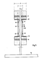
- FIG. 5 shows a schematic cross section through the complete antenna in the plane of a slot antenna 50.
- the two Alford loop antennas 51, 54 are arranged with respect to the slot antenna in such a way that the cross-shaped slot antennas and the two Alford loop antennas have approximately a common phase center.
- the common phase center does not necessarily have to coincide with the geometric center of gravity or the feed point of the antenna.
- the common phase center is a prerequisite for the elevation phase diagrams of the individual antennas 3,4,51 + 54 to match.
- the vertical diagrams of the cross-shaped slot antennas are disturbed by the azimuthally asymmetrical structure of the Alford loop antennas.
- circular, electrically conductive surfaces, z. B. are advantageously between the Alford loop antennas 51, 54 and the slots of the slot antennas in horizontal planes.
- metal sheets 52, 53 are provided.
- the slot antennas couple more strongly with the circular sheets than with the Alford loop antennas, and thus the circular sheets have a symmetrical field effect on the slot antennas. This gives a good congruence of the vertical diagrams.
- the sheets 6 of the slot antennas are widened from the width C to the width D above and below the electrically conductive plates 52, 53.
- the width D is approximately equal to the diameter of the sheets 52.53.
- the Alford loop antennas 51, 54, the circular plates 52, 54 and the slot antennas are held by a tube 7 which is connected to a circular counterweight 55.
- the diameter of the counterweight is 6 m.
- the tube runs through the axis of symmetry of the cross-shaped slot antennas and the Alford loop antennas and, if its diameter is sufficiently small, has no significant influence on the radiation diagrams.
- the effective slot width b (FIG. 1) in this case is composed of the gaps 45, 46 between the tube 7, which has the diameter d, and the plate 6. These gaps each have a width of b / 2.
- the slot with the width b is thus formed by two effective sub-slots, each having the width b / 2.
- the feed lines for the slot antennas and the Alford loop antennas are passed through the tube 7.
Landscapes
- Variable-Direction Aerials And Aerial Arrays (AREA)
- Waveguide Aerials (AREA)
Description
- Die Erfindung geht aus von einer Antenne für ein Drehfunkfeuer. Eine solche Antenne ist aus der DE-PS 1 902 884 bekannt.
- Die Drehfunkfeuer, wie z.B. das bekannte VOR (VOR=VHF Omnidirectional Radio Range, beschrieben in dem Buch «Funksysteme für Ortung und Navigation» von E. Kramar, Verlag Berliner Union GmbH Stuttgart, 1973, Seiten 131-139), senden ein richtungsabhängiges Signal aus, das in einem Flugzeug mit Hilfe eines geeigneten Empfängers zur Bestimmung seines Azimutwertes ausgewertet wird. Das richtungsabhängige Signal wird bei einem VOR durch Rotation eines limagonförmigen Strahlungsdiagramms, das durch Überlagerung eines kreisförmigen mit einem doppelkreisförmigen Strahlungsdiagramm gebildet wird, erzeugt.
- Zur Erzeugung des rotierenden Doppelkreisdiagrammes werden beispielsweise zwei orthogonale Antennen, die jeweils ein doppelkreisförmiges Strahlungsdiagramm haben, wie in dem Buch von E. Kramar beschrieben, über ein Goniometer gespeist.
- Bei den genannten Drehfunkfeuern ist es aus Signalauswertungsgründen wichtig, dass die vertikal polarisierten Strahlungskomponenten möglichst gering sind. Wird die aus der DE-PS 1 902 884 bekannte Antenne bei einem VOR verwendet, dann muss zur Kompensation der Vertikalkomponenten ein Polarisationskäfig vorgesehen werden.
- Es ist Aufgabe der Erfindung, eine Antenne für ein Drehfunkfeuer anzugeben, bei dem der Anteil der Vertikalkomponenten der abgestrahlten Signale möglichst gering ist.
- Die Lösung dieser Aufgabe erfolgt mit den im Anspruch 1 angegebenen Mitteln. Vorteilhafte Weiterbildungen sind den Unteransprüchen zu entnehmen.
- Der Anteil der Vertikalkomponenten der abgestrahlten Signale ist sehr gering. Der Schweigekegel - das ist der Winkelbereich (bezogen auf die Senkrechte über dem Drehfunkfeuer), in dem die vom Flugzeug empfangenen Signale nicht ausgewertet werden dürfen - ist relativ klein (ca. ±30°). Es ist kein Polarisationskäfig notwendig.
-
- Fig. 1 eine Schlitzantenne,
- Fig. 2 die idealisierten Strahlungsdiagramme einer Schlitzantenne in horizontaler und vertikaler Richtung,
- Fig. 3 zwei senkrecht zueinander angeordnete Schlitzantennen,
- Fig. 4 eine Schlitzantenne mit induktiven Endbelastungen und Standrohr, und
- Fig. 5 einen Querschnitt durch die Antenne in der Ebene eines Schlitzstrahlers.
- In der Fig. 1 ist eine einzelne Schlitzantenne dargestellt. Sie besteht aus einem Schlitz 2 mit der Länge L und der Breite b in einem Blech 1 mit der Länge H und der Breite C. Die Längsachse des Schlitzes liegt auf der Längssymmetrieachse des Blechs. Die Abstände des Schlitzes vom Rand des Blechs sind in der Längsrichtung 1 und in der Querrichtung B. Eine solche Schlitzantenne ist an sich aus dem Buch «Taschenbuch der Hochfrequenztechnik» von Meinke/Gundlach, Springer-Verlag, Berlin, 1968, Seite 608 bekannt.
- Ist die Schlitzantenne in Bezug auf die Erdoberfläche senkrecht angeordnet, dann ist ihr Strahlungsdiagramm in der Horizontalebene doppelkreisförmig (Fig.2a). Ihr iedalisiertes Strahlungsdiagramm in der Vertikalebene hat den in Fig. 2b angegebenen Verlauf.
- Zur Erzeugung eines doppelkreisförmigen Strahlungsdiagramms in der Horizontalebene wird eine erste Schlitzantenne mit einer zweiten Schlitzantenne so kombiniert, dass sie sich räumlich durchdringen, dass sie einen Winkel von 90° miteinander bilden und dass sie ein in Bezug auf die Längsachsen der Schlitzantennen symmetrisches Gebilde ergeben (es ergibt sich in der Draufsicht ein gleichschenkliges Kreuz).
- Die Länge der Schlitze ist ungefähr gleich der halben Betriebswellenlänge. Um eine Feinanpassung an die Sendefrequenz zu ermöglichen, sind in den beiden Endbereichen des Schlitzes 12 (Fig.4) in dem Blech 6 weitere kleine Schlitze 8, 81, 82, 83 vorgesehen (Das Rohr 7 ist hier zunächst als nicht vorhanden zu denken). Bei dem Ausführungsbeispiel haben diese kleinen Schlitze jeweils die Form eines «U», dessen Schenkel parallel zur Längsachse des Schlitzes 12 verlaufen. Jeweils ein Schenkel dieser kleinen Schlitze ist senkrecht zur Längsachse des Schlitzes 12 zu diesem Schlitz 12 weitergeführt. Die kleinen Schlitze 8, 81, 82, 83 sind induktive Endbelastungen. Ihre Grösse ist durch Kurzschlussstege 41, 42, 43, 44, die in die U-förmigen Schlitze einsetzbar sind, einstellbar. Dadurch ist auf eine dem Fachmann an sich bekannte Weise eine Anpassung der Schlitzantenne an die Sendefrequenz möglich.
- Die Speisung der Schlitzantennen erfolgt über ein Koaxialkabel 11. Die Leiter des Koaxialkabels sind über ein Symmetrierglied 40 mit den Längsseiten des Schlitzes 12 verbunden. Zwischen den beiden Anschlusspunkten ist eine Phasendifferenz von 180° vorhanden. Die Darstellung in der Fig. 4 ist lediglich schematisch.
- Werden die beiden Schlitzantennen 3, 4 (Fig. 3) mit dem Signal
- U3 = U. - cosωt · cosΩt
bzw. mit dem Signal - U4 = U · sinωt · cosQt
gespeist, wobei Q/2n gleich der Frequenz der Trägerschwingung des abzustrahlenden Signals ist, dann entsteht ein rotierendes Doppelkreisdiagramm, das mit der Winkelgeschwindigkeit ω rotiert. - Einen kleinen Schweigekegel erhält man auf vorteilhafte Weise dann, wenn die Abmessungen einer Schlitzantenne bestimmte Voraussetzungen erfüllen. Es müssen folgende Bedingungen erfüllt sein:
- - der Abstand 1 des Schlitzes vom Blechrand in der Längsrichtung muss grösser als oder gleich einem Fünftel der Betriebswellenlänge sein,
- - der Abstand 1 muss sehr viel grösser als der Abstand B sein.
- Für ein praktisches Ausführungsbeispiel sind die Grössen wie folgt gewählt:



- Zur Erzeugung des kreisförmigen Strahlungsdiagramms, das beim VOR zusätzlich zu dem umlaufenden Doppelkreisdiagramm notwendig ist, sind oberhalb und unterhalb der Schlitze der beiden Schlitzantennen Alford-Rahmenantennen vorgesehen.
- In der Fig. 5 ist ein schematischer Querschnitt durch die komplette Antenne in der Ebene einer Schlitzantenne 50 dargestellt. Die beiden Alford-Rahmenantennen 51, 54 sind in Bezug auf die Schlitzantenne so angeordnet, dass die kreuzförmig angeordneten Schlitzantennen und die beiden Alford-Rahmenantennen näherungsweise ein gemeinsames Phasenzentrum haben. Das gemeinsame Phasenzentrum muss nicht notwendigerweise mit dem geometrischen Schwerpunkt oder dem Speisepunkt der Antenne übereinstimmen. Das gemeinsame Phasenzentrum ist Voraussetzung dafür, dass die Elevationsphasendiagramme der Einzelantennen 3,4,51 + 54 übereinstimmen können.
- Durch den azimutal unsymmetrischen Aufbau der Alford-Rahmenantennen werden die Vertikaldiagramme der kreuzförmig angeordneten Schlitzantennen gestört. Um diese Störung zu beseitigen, sind in vorteilhafter Weise zwischen die Alford-Rahmenantennen 51, 54 und die Schlitze der Schlitzantennen in waagrechten Ebenen kreisförmige, elektrisch leitende Flächen, z. B. Metallbleche 52, 53 vorgesehen. Die Schlitzantennen verkoppeln mit den kreisförmigen Blechen stärker als mit den Alford-Rahmenantennen, und somit haben die kreisförmigen Bleche auf die Schlitzantennen einen symmetrierenden Feldeffekt. Dadurch erhält man eine gute Kongruenz der Vertikaldiagramme. Bei einer Blechbreite C = 0,36 m (Fig. 1) einer Schlitzantenne wird der Durchmesser eines kreisförmigen Bleches zu 0,74 m gewählt. Dies ist auch der Durchmesser einer Alford-Rahmenantenne.
- Um, insbesondere bei hohen Elevationswinkeln, eine verbesserte Unterdrückung der störenden Vertikalkomponenten zu erzielen, werden die Bleche 6 der Schlitzantennen oberhalb und unterhalb der elektrisch leitenden Platten 52, 53 von der Breite C auf die Breite D verbreitert. Die Breite D ist ungefähr gleich dem Durchmesser der Bleche 52,53.
- Die Alford-Rahmenantennen 51, 54, die kreisförmigen Bleche 52, 54 und die Schlitzantennen werden von einem Rohr 7 gehalten, das mit einem kreisförmigen Gegengewicht 55 verbunden ist. Der Durchmesser des Gegengewichts ist 6 m. Bei einer geeigneten Wahl der Höhe der Antenne über dem Gegengewicht und des Gegengewichts über der Erdoberfläche kann man die Kongruenz von Amplituden- und Phasenverhalten in der Elevationsrichtung optimieren.
- Das Rohr verläuft durch die Symmetrieachse der kreuzförmig angeordneten Schlitzantennen und der Alford-Rahmenantennen und hat, wenn sein Durchmesser hinreichend klein ist, auf die Strahlungsdiagramme keinen wesentlichen Einfluss.
- Die wirksame Schlitzbreite b (Fig. 1) setzt sich in diesem Fall zusammen aus den Spalten 45, 46 zwischen dem Rohr 7, das den Durchmesser d hat, und der Platte 6. Diese Spalte haben jeweils eine Breite von b/2. Der Schlitz mit der Breite b wird also gebildet durch zwei wirksame Teilschlitze, die jeweils die Breite b/2 haben. Die Breite C des in Fig. 1 schematisch dargestellten Schlitzstrahlers wird dann

- Die Speiseleitungen für die Schlitzantennen und der Alford-Rahmenantennen werden durch das Rohr 7 geführt.
Claims (7)
Applications Claiming Priority (2)
| Application Number | Priority Date | Filing Date | Title |
|---|---|---|---|
| DE3128952 | 1981-07-22 | ||
| DE19813128952 DE3128952A1 (de) | 1981-07-22 | 1981-07-22 | "antenne fuer ein drehfunkfeuer" |
Publications (3)
| Publication Number | Publication Date |
|---|---|
| EP0070462A2 EP0070462A2 (de) | 1983-01-26 |
| EP0070462A3 EP0070462A3 (en) | 1984-03-28 |
| EP0070462B1 true EP0070462B1 (de) | 1986-12-10 |
Family
ID=6137479
Family Applications (1)
| Application Number | Title | Priority Date | Filing Date |
|---|---|---|---|
| EP82106108A Expired EP0070462B1 (de) | 1981-07-22 | 1982-07-08 | Antenne für ein Drehfunkfeuer |
Country Status (3)
| Country | Link |
|---|---|
| EP (1) | EP0070462B1 (de) |
| CA (1) | CA1190639A (de) |
| DE (2) | DE3128952A1 (de) |
Family Cites Families (4)
| Publication number | Priority date | Publication date | Assignee | Title |
|---|---|---|---|---|
| US2832955A (en) * | 1953-03-24 | 1958-04-29 | Jasik Henry | Antenna system |
| GB1258656A (de) * | 1969-01-22 | 1971-12-30 | ||
| FR2104689B1 (de) * | 1970-07-17 | 1975-01-10 | Thomson Csf | |
| DE2753661A1 (de) * | 1977-12-02 | 1979-06-07 | Philips Patentverwaltung | Notch-antenne mit zueinander gekreuzt angeordneten erregerelementen |
-
1981
- 1981-07-22 DE DE19813128952 patent/DE3128952A1/de not_active Withdrawn
-
1982
- 1982-07-08 EP EP82106108A patent/EP0070462B1/de not_active Expired
- 1982-07-08 DE DE8282106108T patent/DE3274703D1/de not_active Expired
- 1982-07-21 CA CA000407761A patent/CA1190639A/en not_active Expired
Also Published As
| Publication number | Publication date |
|---|---|
| EP0070462A3 (en) | 1984-03-28 |
| DE3128952A1 (de) | 1983-02-10 |
| DE3274703D1 (en) | 1987-01-22 |
| EP0070462A2 (de) | 1983-01-26 |
| CA1190639A (en) | 1985-07-16 |
Similar Documents
| Publication | Publication Date | Title |
|---|---|---|
| DE60120174T2 (de) | Ineinander geschachtelte Kreuzdipolantenne | |
| DE2164868A1 (de) | Rundstrahlantenne | |
| DE2604750A1 (de) | Rundstrahlantennengruppe und eine solche antennengruppe enthaltende elektromagnetische ortungsanordnung | |
| DE1945850A1 (de) | Richtantenne | |
| DE1042674B (de) | Drehfunkfeuerantenne mit verbesserter Vertikalstrahlung | |
| DE2128689A1 (de) | Antennensystem, insbesondere für Satelliten | |
| DE202019102334U1 (de) | Multifrequenz-Antennenvorrichtung | |
| DE2335792A1 (de) | Funknavigations-, insbesondere landesystem | |
| DE861878C (de) | Vertikalantenne, insbesondere fuer Peilsysteme nach dem Adcock-Prinzip | |
| EP0070462A2 (de) | Antenne für ein Drehfunkfeuer | |
| DE2124710A1 (de) | Sende/Empfangs-Antennensystem mit einer Kompensationseinrichtung | |
| DE957857C (de) | Schlitzantenne | |
| DE102018201575B3 (de) | Antennenvorrichtung | |
| DE2135687A1 (de) | Antenne mit linearer Polarisation | |
| DE874033C (de) | Peilanordnung mit Seitenbestimmung | |
| DE3738707C2 (de) | Antennenanordnung | |
| DE2317501A1 (de) | Mittelwellenantenne | |
| DE863681C (de) | Antennensystem | |
| DE895316C (de) | Antennenanordnung zur Erzeugung eines Doppelachtdiagramms | |
| DE2461283A1 (de) | Otationssymmetrische cassegrainantenne | |
| DE2638906A1 (de) | Ghz-antennenanlage fuer ein doppler-radar im x-band | |
| DE690405C (de) | Anordnung zur Erzielung von Richtungsaenderungen eines Antennenrichtdiagramms | |
| DE2150434A1 (de) | Aus mehreren einzelantennen bestehendes peilantennensystem | |
| DE417135C (de) | Empfangseinrichtung fuer drahtlose Telegraphie und Telephonie durch Anwendung zweier oder mehrerer Antennengebilde mit herzfoermiger Charakteristik | |
| DE720841C (de) | Peilantennensystem fuer den Kurzwellenbereich |
Legal Events
| Date | Code | Title | Description |
|---|---|---|---|
| PUAI | Public reference made under article 153(3) epc to a published international application that has entered the european phase |
Free format text: ORIGINAL CODE: 0009012 |
|
| AK | Designated contracting states |
Designated state(s): DE FR GB NL |
|
| PUAL | Search report despatched |
Free format text: ORIGINAL CODE: 0009013 |
|
| AK | Designated contracting states |
Designated state(s): DE FR GB NL |
|
| 17P | Request for examination filed |
Effective date: 19840717 |
|
| 17Q | First examination report despatched |
Effective date: 19860423 |
|
| GRAA | (expected) grant |
Free format text: ORIGINAL CODE: 0009210 |
|
| AK | Designated contracting states |
Kind code of ref document: B1 Designated state(s): DE FR GB NL |
|
| REF | Corresponds to: |
Ref document number: 3274703 Country of ref document: DE Date of ref document: 19870122 |
|
| ET | Fr: translation filed | ||
| REG | Reference to a national code |
Ref country code: FR Ref legal event code: TP |
|
| PLBE | No opposition filed within time limit |
Free format text: ORIGINAL CODE: 0009261 |
|
| STAA | Information on the status of an ep patent application or granted ep patent |
Free format text: STATUS: NO OPPOSITION FILED WITHIN TIME LIMIT |
|
| REG | Reference to a national code |
Ref country code: GB Ref legal event code: 732 |
|
| 26N | No opposition filed | ||
| NLS | Nl: assignments of ep-patents |
Owner name: ALCATEL N.V. TE AMSTERDAM. |
|
| PGFP | Annual fee paid to national office [announced via postgrant information from national office to epo] |
Ref country code: NL Payment date: 19900731 Year of fee payment: 9 |
|
| PG25 | Lapsed in a contracting state [announced via postgrant information from national office to epo] |
Ref country code: NL Effective date: 19920201 |
|
| NLV4 | Nl: lapsed or anulled due to non-payment of the annual fee | ||
| PGFP | Annual fee paid to national office [announced via postgrant information from national office to epo] |
Ref country code: GB Payment date: 19980612 Year of fee payment: 17 |
|
| PGFP | Annual fee paid to national office [announced via postgrant information from national office to epo] |
Ref country code: FR Payment date: 19980629 Year of fee payment: 17 |
|
| PGFP | Annual fee paid to national office [announced via postgrant information from national office to epo] |
Ref country code: DE Payment date: 19980630 Year of fee payment: 17 |
|
| PG25 | Lapsed in a contracting state [announced via postgrant information from national office to epo] |
Ref country code: GB Free format text: LAPSE BECAUSE OF NON-PAYMENT OF DUE FEES Effective date: 19990708 |
|
| PG25 | Lapsed in a contracting state [announced via postgrant information from national office to epo] |
Ref country code: FR Free format text: THE PATENT HAS BEEN ANNULLED BY A DECISION OF A NATIONAL AUTHORITY Effective date: 19990731 |
|
| GBPC | Gb: european patent ceased through non-payment of renewal fee |
Effective date: 19990708 |
|
| PG25 | Lapsed in a contracting state [announced via postgrant information from national office to epo] |
Ref country code: DE Free format text: LAPSE BECAUSE OF NON-PAYMENT OF DUE FEES Effective date: 20000503 |
|
| REG | Reference to a national code |
Ref country code: FR Ref legal event code: ST |