EP0069890A2 - Device for the displacement of a housing or roll stand - Google Patents
Device for the displacement of a housing or roll stand Download PDFInfo
- Publication number
- EP0069890A2 EP0069890A2 EP82105531A EP82105531A EP0069890A2 EP 0069890 A2 EP0069890 A2 EP 0069890A2 EP 82105531 A EP82105531 A EP 82105531A EP 82105531 A EP82105531 A EP 82105531A EP 0069890 A2 EP0069890 A2 EP 0069890A2
- Authority
- EP
- European Patent Office
- Prior art keywords
- piston
- cylinder unit
- roll
- roll stand
- stand
- Prior art date
- Legal status (The legal status is an assumption and is not a legal conclusion. Google has not performed a legal analysis and makes no representation as to the accuracy of the status listed.)
- Withdrawn
Links
- 238000006073 displacement reaction Methods 0.000 title abstract description 10
- 238000009434 installation Methods 0.000 claims abstract description 13
- 238000005096 rolling process Methods 0.000 claims abstract description 6
- 230000008878 coupling Effects 0.000 claims abstract description 5
- 238000010168 coupling process Methods 0.000 claims abstract description 5
- 238000005859 coupling reaction Methods 0.000 claims abstract description 5
- 239000002184 metal Substances 0.000 description 1
Images
Classifications
-
- B—PERFORMING OPERATIONS; TRANSPORTING
- B21—MECHANICAL METAL-WORKING WITHOUT ESSENTIALLY REMOVING MATERIAL; PUNCHING METAL
- B21B—ROLLING OF METAL
- B21B31/00—Rolling stand structures; Mounting, adjusting, or interchanging rolls, roll mountings, or stand frames
- B21B31/08—Interchanging rolls, roll mountings, or stand frames, e.g. using C-hooks; Replacing roll chocks on roll shafts
- B21B31/10—Interchanging rolls, roll mountings, or stand frames, e.g. using C-hooks; Replacing roll chocks on roll shafts by horizontally displacing, i.e. horizontal roll changing
- B21B31/103—Manipulators or carriages therefor
-
- B—PERFORMING OPERATIONS; TRANSPORTING
- B21—MECHANICAL METAL-WORKING WITHOUT ESSENTIALLY REMOVING MATERIAL; PUNCHING METAL
- B21B—ROLLING OF METAL
- B21B31/00—Rolling stand structures; Mounting, adjusting, or interchanging rolls, roll mountings, or stand frames
- B21B31/02—Rolling stand frames or housings; Roll mountings ; Roll chocks
- B21B2031/026—Transverse shifting the stand
Definitions
- the invention relates to a device for moving a roll installation or a roll stand on a web running transversely to the rolling direction with a piston-cylinder unit arranged below the roll drive spindles parallel to the moving track.
- the object of the invention is to provide a simple and reliable hydraulic shifting device which enables a large displacement distance in a small space.
- a piston-cylinder unit connected to the roll installation or a roll stand is connected via a coupling piece, which is defined parallel to the sliding path, to a piston-cylinder unit arranged in a stationary manner under the roll stand, in such a way that the installation position of the Roller installation or the roll stand corresponds to a retracted position of the associated piston-cylinder unit and an extended position of the stationary piston-cylinder unit.
- the device can also be installed under a small distance between the roll stand and gear under the roll stand and the spindles, so that special passages on the gear and motor are not required.
- the clutch piece designed as a cross lever, the upper arm of which is articulated to the piston-cylinder unit connected to the roll installation or the roll stand and the lower arm of which is articulated to the fixed piston-cylinder unit and on the side arms of which guide rollers are mounted, with a lower and an upper one parallel to the sliding track are assigned.
- the pressure medium cylinder 13 is articulated on the upper arm of a cross lever 15 by bolts 16.
- the cross lever 15 is provided with wheels 17 which are arranged in a U-guide 18 arranged between the roller stand 1 and the gear 8 parallel to the extension rails 11 to run.
- the piston rod 19 of a pressure medium cylinder 20 which is arranged horizontally under the roll stand and fastened to a roll stand 1, is articulated by a bolt 21.
Landscapes
- Engineering & Computer Science (AREA)
- Mechanical Engineering (AREA)
- Bending Of Plates, Rods, And Pipes (AREA)
- Registering, Tensioning, Guiding Webs, And Rollers Therefor (AREA)
Abstract
Description
Die Erfindung betrifft eine Vorrichtung zum Verschieben eines Walzeneinbaus oder eines Walzgerüstes auf einer quer zur Walzrichtung verlaufenden Bahn mit einer unterhalb der Walzenantriebsspindeln parallel zur Verschiebebahn angeordneten Kolben-Zylinder-Einheit.The invention relates to a device for moving a roll installation or a roll stand on a web running transversely to the rolling direction with a piston-cylinder unit arranged below the roll drive spindles parallel to the moving track.
In Blech und Profilwalzwerken werden zum Walzenwechsel Walzeneinbauten bzw. Walzgerüste auf horizontalen Bahnen quer zur Walzrichtung verschoben. Als Verschiebeantriebe sind Spindeltriebe, Zahnstangentriebe und beidseitig beaufschlagbare Kolben-Zylinder-Einheiten bekannt.In sheet metal and profile rolling mills, roll internals or roll stands are moved horizontally across the rolling direction to change the rolls. Spindle drives, rack and pinion drives and piston-cylinder units which can be acted upon on both sides are known as displacement drives.
Zur Freihaltung des Verschiebebereichs ist es vorteilhaft, die Kolben-Zylinder-Einheiten unterhalb der Antriebsspindeln der Walzen anzuordnen. Der Platz zwischen Walzgerüst und Walzengetriebe reicht jedoch manchmal nicht aus, um für lange Verschiebewege erforderliche langhubige Zylinder unterzubringen. Teleskopzylinder werden von den Betriebsleitungen wegen der hohen Kosten und der ungünstigen Betriebsbedingungen nur ungern akzeptiert.To keep the displacement area clear, it is advantageous to have the piston-cylinder units below the drive pin to arrange the rollers. However, the space between the roll stand and the roller gearbox is sometimes not sufficient to accommodate the long-stroke cylinders required for long displacement distances. Operating lines are reluctant to accept telescopic cylinders due to the high costs and unfavorable operating conditions.
Aufgabe der Erfindung ist die Schaffung einer einfachen und betriebssicheren hydraulischen Verschiebevorrichtung, die bei geringem Platzbedarf einen großen Verschiebeweg ermöglicht.The object of the invention is to provide a simple and reliable hydraulic shifting device which enables a large displacement distance in a small space.
Nach der Erfindung wird dies dadurch erreicht, daß eine mit dem Walzeneinbau oder einem Walzgerüst verbundene Kolben-Zylinder-Einheit über ein parallel zur Verschiebebahn definiert geführtes Kupplungsstück derart mit einer unter dem Walzgerüst ortsfest angeordneten Kolben-Zylinder-Einheit verbunden ist, daß der Einbaustellung des Walzeneinbaus oder des Walzgerüstes eine eingefahrene Position der damit verbundenen Kolben-Zylinder-Einheit und eine ausgefahrene Position der ortsfesten Kolben-Zylinder-Einheit entspricht.According to the invention, this is achieved in that a piston-cylinder unit connected to the roll installation or a roll stand is connected via a coupling piece, which is defined parallel to the sliding path, to a piston-cylinder unit arranged in a stationary manner under the roll stand, in such a way that the installation position of the Roller installation or the roll stand corresponds to a retracted position of the associated piston-cylinder unit and an extended position of the stationary piston-cylinder unit.
Auf diese Weise wird eine einfache und betriebssichere Verschiebevorrichtung geschaffen, mit der bei geringem Platzbedarf ein großer Verschiebeweg erreichbar ist. Die Vorrichtung kann auch bei geringem Abstand zwischen Walzgerüst und Getriebe unter dem Walzgerüst und den Spindeln eingebaut werden, so daß besondere Durchlässe am Getriebe und Motor nicht erforderlich sind.In this way, a simple and reliable displacement device is created, with which a large displacement distance can be achieved with a small space requirement. The device can also be installed under a small distance between the roll stand and gear under the roll stand and the spindles, so that special passages on the gear and motor are not required.
Gemäß einem weiteren Merkmal der Erfindung ist das Kupplungsstück als Kreuzhebel ausgebildet, dessen oberer Arm an der mit dem Walzeneinbau oder dem Walzgerüst verbundenen Kolben-Zylinder-Einheit und dessen unterer Arm an der ortsfesten Kolben-Zylinder-Einheit angelenkt sind und an dessen Seitenarmen Führungsrollen gelagert sind, denen eine untere und eine obere parallel zur Verschiebebahn verlaufende Führungsbahn zugeordnet sind.According to a further feature of the invention, the clutch piece designed as a cross lever, the upper arm of which is articulated to the piston-cylinder unit connected to the roll installation or the roll stand and the lower arm of which is articulated to the fixed piston-cylinder unit and on the side arms of which guide rollers are mounted, with a lower and an upper one parallel to the sliding track are assigned.
In der Zeichnung ist ein Ausführungsbeispiel der Erfindung dargestellt. Es zeigen
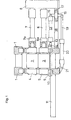
- Fig. 1 schematisch ein Walzgerüst mit einer Verschiebevorrichtung für den Walzeneinbau und
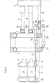
- Fig. 2 das Walzgerüst mit aus dem Gerüst gefahrenen Walzensatz.
- Fig. 1 shows schematically a roll stand with a displacement device for roll installation and
- Fig. 2 shows the roll stand with the set of rolls moved out of the stand.
Bei dem dargestellten Walzgerüst sind in Walzenständern 1 Walzen 2, 3 mit ihren Einbaustücken 4, 5 gelagert. Die Walzen 2, 3 sind über Spindeln 6, 7 und Kupplungstreffer 6a, 7a mit einem Getriebe 8 verbunden. Die Einbaustücke 5 der unteren Walze 3 stehen auf einem Ausfahrwagen 9, der mit Räder 10 auf Ausfahrschienen 11 aus dem Walzgerüst fahrbar ist. An dem Ausfahrwagen 9 ist die Kolbenstange 12 eines horizontal angeordneten Druckmittelzylinders 13 durch einen Bolzen 14 angebracht.In the roll stand shown, 1
Der Druckmittelzylinder 13 ist am oberen Arm eines Kreuzhebels 15 durch Bolzen 16 angelenkt. Zur definierten Horizontalführung ist der Kreuzhebel 15 mit Rädern 17 versehen, die in einer zwischen Walzenständer 1 und Getriebe 8 parallel zu den Ausfahrschienen 11 angeordneten U-Führung 18 laufen. An einem unteren Arm des Kreuzhebels 15 ist die Kolbenstange 19 eines unter dem Walzgerüst horizontal angeordneten und an einem Walzenständer 1 befestigten Druckmittelzylinders 20 durch einen Bolzen 21 angelenkt.The
Zum Ausbauen der Walzen 2, 3 mit ihren Einbaustücken 4, 5 werden die Kolbenstange 12 und 19 durch Beaufschlagung der Druckmittelzylinder 13 und 20 ausgefahren. Ein neuer Walzensatz wird anschließend durch entgegengesetzte Beaufschlagung der Zylinder 13, 20 in die Einbaustellung gefahren.To remove the
Claims (2)
dadurch gekennzeichnet,
daß die mit dem Walzeneinbau oder einem Walzgerüst verbundene Kolben-Zylinder-Einheit (12, 13) über ein parallel zur Verschiebebahn (11) definiert geführtes Kupplungsstück derart mit einer unter dem Walzgerüst ortsfest angeordneten Kolben-Zylinder-Einheit (19, 20) verbunden ist, daß der Einbaustellung des Walzeneinbaus (2, 3, 4, 5) oder des Walzgerüstes eine eingefahrene Position der damit verbundenen Kolben-Zylinder-Einheit (12, 13) und eine Ausfahrposition der ortsfesten Kolben-Zylinder-Einheit (19, 20) entspricht.1. Device for displacing a roll installation or a rolling stand on a web running transversely to the rolling direction with a piston-cylinder unit arranged below the roll drive spindles parallel to the displacing web,
characterized,
that the piston-cylinder unit (12, 13) connected to the roll installation or a roll stand is connected via a coupling piece, which is guided in a defined manner parallel to the sliding track (11), to a piston-cylinder unit (19, 20) which is arranged in a stationary manner under the roll stand that the installation position of the roller installation (2, 3, 4, 5) or the roll stand corresponds to a retracted position of the piston-cylinder unit (12, 13) connected to it and an extended position of the stationary piston-cylinder unit (19, 20) .
dadurch gekennzeichnet,
daß das Kupplungsstück als Kreuzhebel (15) ausgebildet ist, dessen oberer Arm an der an dem Walzeneinbau oder Walzgerüst angekuppelten Kolben-Zylinder-Einheit (12, 13) und dessen unterer Arm an der ortsfesten Kolben-Zylinder-Einheit (19, 20) angelenkt sind und an dessen Seitenarmen Rollen (17) gelagert sind, denen eine. untere und eine obere Führungsbahn (18) zugeordnet sind.2. Device according to claim 1,
characterized,
that the coupling piece is designed as a cross lever (15), the upper arm of which is articulated to the piston-cylinder unit (12, 13) coupled to the roll installation or roll stand and the lower arm of which is articulated to the stationary piston-cylinder unit (19, 20) are and on the side arms rollers (17) are mounted, which one. lower and an upper guide track (18) are assigned.
Applications Claiming Priority (2)
| Application Number | Priority Date | Filing Date | Title |
|---|---|---|---|
| DE3127907 | 1981-07-15 | ||
| DE19813127907 DE3127907A1 (en) | 1981-07-15 | 1981-07-15 | DEVICE FOR MOVING A ROLL INSTALLATION OR ROLLING DEVICE |
Publications (2)
| Publication Number | Publication Date |
|---|---|
| EP0069890A2 true EP0069890A2 (en) | 1983-01-19 |
| EP0069890A3 EP0069890A3 (en) | 1983-07-20 |
Family
ID=6136951
Family Applications (1)
| Application Number | Title | Priority Date | Filing Date |
|---|---|---|---|
| EP82105531A Withdrawn EP0069890A3 (en) | 1981-07-15 | 1982-06-24 | Device for the displacement of a housing or roll stand |
Country Status (2)
| Country | Link |
|---|---|
| EP (1) | EP0069890A3 (en) |
| DE (1) | DE3127907A1 (en) |
Cited By (5)
| Publication number | Priority date | Publication date | Assignee | Title |
|---|---|---|---|---|
| EP0170866B1 (en) * | 1984-07-18 | 1988-05-18 | Sms Schloemann-Siemag Aktiengesellschaft | One-strand arrangement of millstands with a fixed rolling centre for rolling rod, small sections, billets or tubes |
| EP0607541A1 (en) * | 1993-01-18 | 1994-07-27 | Paul Troester Maschinenfabrik | Calender and calendering installation |
| FR2746053A1 (en) * | 1996-03-15 | 1997-09-19 | Togum | Shaping of extruded foodstuffs by quick release rollers |
| CN104741381A (en) * | 2015-03-31 | 2015-07-01 | 中国重型机械研究院股份公司 | Servo roll changing device |
| CN105562436A (en) * | 2015-12-25 | 2016-05-11 | 中国重型机械研究院股份公司 | Follow-up type roller change trolley |
Families Citing this family (2)
| Publication number | Priority date | Publication date | Assignee | Title |
|---|---|---|---|---|
| DE3804101A1 (en) * | 1988-02-10 | 1989-08-24 | Sprimag Spritzmaschbau Gmbh | Transport apparatus for chain-type spraying machines, in particular for ceramic and enamelling machines |
| DE102005061085A1 (en) * | 2005-12-21 | 2007-06-28 | Khd Humboldt Wedag Gmbh | Double roller machine for pressure treatment of granular material, especially a roller press for comminuting, compacting or briquetting, comprises a machine table with a reciprocally moving table top underneath a slip-on gear mechanism |
Citations (4)
| Publication number | Priority date | Publication date | Assignee | Title |
|---|---|---|---|---|
| DE669528C (en) * | 1936-05-23 | 1938-12-28 | Lange & Geilen Maschinenfabrik | Hydraulic drive device for reciprocating parts of machine tools, in particular short planing machines |
| AT205832B (en) * | 1957-10-09 | 1959-10-26 | Schwermaschb Heinrich Rau Veb | Movement device, especially for the table of a planer |
| DE1752537A1 (en) * | 1967-06-13 | 1971-07-29 | Fielding & Platt Ltd | Hydraulic press |
| DE2554486A1 (en) * | 1975-12-04 | 1977-06-08 | Schloemann Siemag Ag | Rolling mill stand drawout slide - with two crosspieces for alternate coupling to piston crossheads |
-
1981
- 1981-07-15 DE DE19813127907 patent/DE3127907A1/en not_active Withdrawn
-
1982
- 1982-06-24 EP EP82105531A patent/EP0069890A3/en not_active Withdrawn
Patent Citations (4)
| Publication number | Priority date | Publication date | Assignee | Title |
|---|---|---|---|---|
| DE669528C (en) * | 1936-05-23 | 1938-12-28 | Lange & Geilen Maschinenfabrik | Hydraulic drive device for reciprocating parts of machine tools, in particular short planing machines |
| AT205832B (en) * | 1957-10-09 | 1959-10-26 | Schwermaschb Heinrich Rau Veb | Movement device, especially for the table of a planer |
| DE1752537A1 (en) * | 1967-06-13 | 1971-07-29 | Fielding & Platt Ltd | Hydraulic press |
| DE2554486A1 (en) * | 1975-12-04 | 1977-06-08 | Schloemann Siemag Ag | Rolling mill stand drawout slide - with two crosspieces for alternate coupling to piston crossheads |
Cited By (5)
| Publication number | Priority date | Publication date | Assignee | Title |
|---|---|---|---|---|
| EP0170866B1 (en) * | 1984-07-18 | 1988-05-18 | Sms Schloemann-Siemag Aktiengesellschaft | One-strand arrangement of millstands with a fixed rolling centre for rolling rod, small sections, billets or tubes |
| EP0607541A1 (en) * | 1993-01-18 | 1994-07-27 | Paul Troester Maschinenfabrik | Calender and calendering installation |
| FR2746053A1 (en) * | 1996-03-15 | 1997-09-19 | Togum | Shaping of extruded foodstuffs by quick release rollers |
| CN104741381A (en) * | 2015-03-31 | 2015-07-01 | 中国重型机械研究院股份公司 | Servo roll changing device |
| CN105562436A (en) * | 2015-12-25 | 2016-05-11 | 中国重型机械研究院股份公司 | Follow-up type roller change trolley |
Also Published As
| Publication number | Publication date |
|---|---|
| DE3127907A1 (en) | 1983-02-24 |
| EP0069890A3 (en) | 1983-07-20 |
Similar Documents
| Publication | Publication Date | Title |
|---|---|---|
| DE1283782B (en) | Universal rolling frame with brackets bridging the stand window | |
| DE2353731C3 (en) | Device for changing rolls on a roll stand, in particular a universal roll stand | |
| EP0069890A2 (en) | Device for the displacement of a housing or roll stand | |
| EP3352923B1 (en) | Roll stand and method for changing work rolls | |
| DE3529364C2 (en) | ||
| DE19922373A1 (en) | Ingots used in hot rolling have a double acting hydraulic piston cylinder unit with both ends connected to guide pieces | |
| DE1402965A1 (en) | Removable device for turning, hole enlarging, milling, drilling and the like. of workpieces of larger dimensions | |
| EP0388865B1 (en) | Rolling train for roll forming strips (straight bead tube welding) | |
| EP0329998B1 (en) | Rolling train, especially one in a section-rolling mill | |
| EP0597265B1 (en) | Roll stand | |
| EP0476468B1 (en) | Device for exchanging the pressing tools of a pressing machine | |
| EP0002047B1 (en) | Rolling stand, e.g. universal rolling stand | |
| DE3226871C2 (en) | Inclined mill for rolling tubes | |
| DE3237904A1 (en) | Device for the exchange of rolls in a tube rolling mill | |
| DE4442567A1 (en) | Simplified driver unit for rolled strip | |
| DE19610132C2 (en) | Rail vehicle with at least one car body supported on wheels | |
| DE3918242A1 (en) | Spacers esp. for working rollers in quatro-rolling stand - are freely movable in guide grooves in roller installation parts to facilitate roller replacement without damage to new rollers | |
| DE19850999C1 (en) | Automatic changing appliance has changing plate for molding implement, press-bedplate, drive cog wheel, toothed bar and chain drive | |
| DE10052855C2 (en) | Roll changing device | |
| DE2227549A1 (en) | ROLLING MILL | |
| DE3902889C2 (en) | Open rolling mill with roll stands arranged side by side | |
| DE202010016581U1 (en) | wheelset | |
| EP0029018B1 (en) | Strand guiding for a curved continuous casting plant | |
| DE2721436A1 (en) | Draw chain mounted on roll changing wagon - for rapid replacement of worn rolls in rolling mills | |
| DE2929423A1 (en) | Roll changing equipment for universal rolling mill - where all four rolls can be rapidly transferred sideways onto roll changing wagon |
Legal Events
| Date | Code | Title | Description |
|---|---|---|---|
| PUAI | Public reference made under article 153(3) epc to a published international application that has entered the european phase |
Free format text: ORIGINAL CODE: 0009012 |
|
| 17P | Request for examination filed |
Effective date: 19820624 |
|
| AK | Designated contracting states |
Designated state(s): BE DE FR IT LU NL |
|
| PUAL | Search report despatched |
Free format text: ORIGINAL CODE: 0009013 |
|
| AK | Designated contracting states |
Designated state(s): BE DE FR IT LU NL |
|
| STAA | Information on the status of an ep patent application or granted ep patent |
Free format text: STATUS: THE APPLICATION IS DEEMED TO BE WITHDRAWN |
|
| 18D | Application deemed to be withdrawn |
Effective date: 19840425 |
|
| RIN1 | Information on inventor provided before grant (corrected) |
Inventor name: WOCHNIK, JOSEF Inventor name: HEISTERKAMP, HANS FRIEDRICH |