EP0067047A1 - Teilezuführeinrichtung - Google Patents
Teilezuführeinrichtung Download PDFInfo
- Publication number
- EP0067047A1 EP0067047A1 EP82302878A EP82302878A EP0067047A1 EP 0067047 A1 EP0067047 A1 EP 0067047A1 EP 82302878 A EP82302878 A EP 82302878A EP 82302878 A EP82302878 A EP 82302878A EP 0067047 A1 EP0067047 A1 EP 0067047A1
- Authority
- EP
- European Patent Office
- Prior art keywords
- magnetic
- parts
- pickup
- feeding device
- uppermost
- Prior art date
- Legal status (The legal status is an assumption and is not a legal conclusion. Google has not performed a legal analysis and makes no representation as to the accuracy of the status listed.)
- Withdrawn
Links
Images
Classifications
-
- B—PERFORMING OPERATIONS; TRANSPORTING
- B65—CONVEYING; PACKING; STORING; HANDLING THIN OR FILAMENTARY MATERIAL
- B65G—TRANSPORT OR STORAGE DEVICES, e.g. CONVEYORS FOR LOADING OR TIPPING, SHOP CONVEYOR SYSTEMS OR PNEUMATIC TUBE CONVEYORS
- B65G59/00—De-stacking of articles
- B65G59/02—De-stacking from the top of the stack
- B65G59/04—De-stacking from the top of the stack by suction or magnetic devices
- B65G59/045—De-stacking from the top of the stack by suction or magnetic devices with a stepwise upward movement of the stack
-
- B—PERFORMING OPERATIONS; TRANSPORTING
- B25—HAND TOOLS; PORTABLE POWER-DRIVEN TOOLS; MANIPULATORS
- B25J—MANIPULATORS; CHAMBERS PROVIDED WITH MANIPULATION DEVICES
- B25J15/00—Gripping heads and other end effectors
- B25J15/06—Gripping heads and other end effectors with vacuum or magnetic holding means
Definitions
- the present invention relates to a part-feeding device used for, for example, an assembling robot system.
- a part-feeding device In an assembling robot system, a part-feeding device has been used for holding a large number of relatively small and thin parts, such as wave-washers, which are laminated in an up and down motion.
- this part-feeding device the uppermost parts are separated one by one from the other parts and are fed to the robot.
- Such separation of the parts one by one is performed by an air suction means which is, for example, provided in a hand of the robot.
- a part-feeding device for separating a plurality of laminated magnetic parts one by one and feeding the uppermost magnetic part thereof, comprising: means for generating a magnetic field to the magnetic parts so as to generate a repulsive force between the magnetic parts; and a pickup means for picking up the uppermost magnetic part magnetized by the magnetic field-generating means.
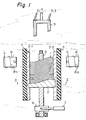
- a large number of magnetic parts such as wave-washers 1 are laminated in an up and down motion on a base 2.
- This base 2 moves up and down along two guiderails 3-1 and 3-2 on the inner surface of a nonmagnetic acryl resin cylinder 4 and a screw 5 located at the center of the cylinder 4.
- the up and down motion is performed by a ratchet wheel 6 fixed to the screw 5.
- This ratchet wheel 6 is rotated by an air cylinder 7 at a pitch of, for example, 90 degrees.
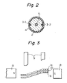
- an electromagnet 8 is provided for generating a magnetic field so as to create a repulsive force between the parts 1 and, accordingly, to separate the parts 1 from each other. Particularly, in this case, in view of gravitation, there is generated an air gap between the uppermost magnetic part and the magnetic part immediately beneath it.
- a pickup 9 for picking up the uppermost part is provided with a hand of a robot (not shown).
- the pickup 9 is comprised of an air suction means.
- the pickup 9 descends to suck up only the uppermost magnetic part la (Fig. 3). In this case, air flows as indicated by the arrows X (Fig. 1). Then the pickup 9 holding the part la is moved to a working table (not shown) of the robot system and, accordingly, the part la is mounted on the working table.
- each part 1 (Fig. 1) is 0.25 mm in thickness and the screw 5 generates a 1 mm lead per one rotation. Then when the air cylinder 7 is operated by one stroke, the screw 5 rotates 90 degrees and, accordingly, the base 2 feeds up at a distance equal to the thickness of one magnetic part 1. After that, the pickup 9 sucks up the second part lb.
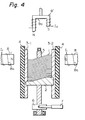
- a pickup 9' comprised of a magnetic field-generating means (electromagnet) is provided instead of the pickup 9 of Fig. 1 comprised of an air suction means.
- the operation of the pickup 9' is similar to that of the pickup 9.
- the pickup 9' descends and a current I 2 -is supplied to a coil 9a of the pickup 9', the magnetic force induced by the pickup 9' is small as compared with the magnetic force (repulsive magnetic force) between the parts induced by the electromagnet 8. Therefore, even in this case, the pickup 9' picks up only the uppermost part.
- the part-feeding device according to the present invention is advantageous in that the feeding of two or more magnetic parts simultaneously does not occur since the laminated magnetic parts are definitely separated one by one by the magnetic field-generating means (the electromagnet 8).
Applications Claiming Priority (2)
| Application Number | Priority Date | Filing Date | Title |
|---|---|---|---|
| JP56084962A JPS57199728A (en) | 1981-06-04 | 1981-06-04 | Parts feeder |
| JP84962/81 | 1981-06-04 |
Publications (1)
| Publication Number | Publication Date |
|---|---|
| EP0067047A1 true EP0067047A1 (de) | 1982-12-15 |
Family
ID=13845248
Family Applications (1)
| Application Number | Title | Priority Date | Filing Date |
|---|---|---|---|
| EP82302878A Withdrawn EP0067047A1 (de) | 1981-06-04 | 1982-06-03 | Teilezuführeinrichtung |
Country Status (3)
| Country | Link |
|---|---|
| EP (1) | EP0067047A1 (de) |
| JP (1) | JPS57199728A (de) |
| KR (1) | KR840000342A (de) |
Cited By (3)
| Publication number | Priority date | Publication date | Assignee | Title |
|---|---|---|---|---|
| FR2640946A1 (en) * | 1988-12-23 | 1990-06-29 | Peugeot | Machine for automatic conveying and destacking of workpieces having a complex shape |
| DE19961648A1 (de) * | 1999-12-21 | 2001-07-05 | Nsm Magnettech Gmbh & Co Kg | Verfahren und Einrichtung zum Entstapeln von Teilen aus elektrisch leitendem Werkstoff |
| CN116142764A (zh) * | 2023-04-12 | 2023-05-23 | 徐州南普机电科技有限公司 | 一种电机磁片运输用工具 |
Families Citing this family (1)
| Publication number | Priority date | Publication date | Assignee | Title |
|---|---|---|---|---|
| CN112978376B (zh) * | 2021-02-03 | 2022-11-18 | 丰顺县帆凯实业有限公司 | 一种t铁上料装置 |
Citations (4)
| Publication number | Priority date | Publication date | Assignee | Title |
|---|---|---|---|---|
| US2999687A (en) * | 1958-12-23 | 1961-09-12 | American Can Co | Sheet feeder |
| DE1266687B (de) * | 1965-01-05 | 1968-04-18 | Schuler Ges Mit Beschraenkter | Transportvorrichtung fuer Platinen aus ferromagnetischem Werkstoff, insbesondere bei Werkzeugmaschinen |
| DE2103954B2 (de) * | 1971-01-28 | 1974-07-25 | Keller & Knappich Gmbh, 8900 Augsburg | Vorrichtung zum paarweisen Einlegen von Werkstückhalbteilen |
| US4024963A (en) * | 1975-05-07 | 1977-05-24 | Hautau Charles F | Apparatus for transferring articles |
-
1981
- 1981-06-04 JP JP56084962A patent/JPS57199728A/ja active Pending
-
1982
- 1982-06-02 KR KR1019820002465A patent/KR840000342A/ko unknown
- 1982-06-03 EP EP82302878A patent/EP0067047A1/de not_active Withdrawn
Patent Citations (4)
| Publication number | Priority date | Publication date | Assignee | Title |
|---|---|---|---|---|
| US2999687A (en) * | 1958-12-23 | 1961-09-12 | American Can Co | Sheet feeder |
| DE1266687B (de) * | 1965-01-05 | 1968-04-18 | Schuler Ges Mit Beschraenkter | Transportvorrichtung fuer Platinen aus ferromagnetischem Werkstoff, insbesondere bei Werkzeugmaschinen |
| DE2103954B2 (de) * | 1971-01-28 | 1974-07-25 | Keller & Knappich Gmbh, 8900 Augsburg | Vorrichtung zum paarweisen Einlegen von Werkstückhalbteilen |
| US4024963A (en) * | 1975-05-07 | 1977-05-24 | Hautau Charles F | Apparatus for transferring articles |
Cited By (4)
| Publication number | Priority date | Publication date | Assignee | Title |
|---|---|---|---|---|
| FR2640946A1 (en) * | 1988-12-23 | 1990-06-29 | Peugeot | Machine for automatic conveying and destacking of workpieces having a complex shape |
| DE19961648A1 (de) * | 1999-12-21 | 2001-07-05 | Nsm Magnettech Gmbh & Co Kg | Verfahren und Einrichtung zum Entstapeln von Teilen aus elektrisch leitendem Werkstoff |
| CN116142764A (zh) * | 2023-04-12 | 2023-05-23 | 徐州南普机电科技有限公司 | 一种电机磁片运输用工具 |
| CN116142764B (zh) * | 2023-04-12 | 2023-09-22 | 徐州南普机电科技有限公司 | 一种电机磁片运输用工具 |
Also Published As
| Publication number | Publication date |
|---|---|
| JPS57199728A (en) | 1982-12-07 |
| KR840000342A (ko) | 1984-02-18 |
Similar Documents
| Publication | Publication Date | Title |
|---|---|---|
| US7159307B2 (en) | Electrically operated chucking apparatus | |
| CN1121341C (zh) | 部品对齐装置 | |
| FI913484A (fi) | Roterande mataranordning foer exakt placering av arkelement pao flata underlag. | |
| CN110104429B (zh) | 一种智能贴装装置及智能贴装方法 | |
| EP0914034A3 (de) | Speisevorrichtung für elektrische Komponenten | |
| EP0067047A1 (de) | Teilezuführeinrichtung | |
| JPH0245360B2 (de) | ||
| ATE204553T1 (de) | Vorrichtung zum wahlweisen zuführen von bögen von zwei magazinen in einer büromaschine | |
| CN110548817A (zh) | 用于铝片材的自动拆堆的涡流坯料分离 | |
| JP3515054B2 (ja) | リニアモータが適用されたヘッドモジュール | |
| CN213770477U (zh) | 磁吸拾取机构 | |
| EP0777313B1 (de) | Motor und elektronische Teilenbefestigungsvorrichtung enthaltende den Motor | |
| CN209080382U (zh) | 一种摄像模组剥单设备 | |
| EP0796700A3 (de) | Drehantriebsvorrichtung für einen Werkzeugmaschinentisch | |
| CN210001173U (zh) | 一种智能贴装装置 | |
| ATE8236T1 (de) | Vorrichtung zum vereinzeln und ordnen von sich verhakenden im haufwerk vorliegenden metallischen werkstuecken. | |
| CN202587617U (zh) | 一种贴片机的送料器 | |
| CN215618549U (zh) | 一种自动打靶机机械手 | |
| CN219015327U (zh) | 编码器及电机 | |
| CN216188533U (zh) | 一种汽缸推送传输带加料的柔性选料机 | |
| JP3241094B2 (ja) | 軸状電子部品の搬送ドラム | |
| EP0510925A3 (de) | Adhäsionsbrecher für Blattstapel | |
| JPH0343176A (ja) | ツールインターフェイスユニット | |
| KR960005728B1 (ko) | 타그부착장치 | |
| JPH0355554Y2 (de) |
Legal Events
| Date | Code | Title | Description |
|---|---|---|---|
| PUAI | Public reference made under article 153(3) epc to a published international application that has entered the european phase |
Free format text: ORIGINAL CODE: 0009012 |
|
| 17P | Request for examination filed |
Effective date: 19820716 |
|
| AK | Designated contracting states |
Designated state(s): DE FR GB IT |
|
| STAA | Information on the status of an ep patent application or granted ep patent |
Free format text: STATUS: THE APPLICATION IS DEEMED TO BE WITHDRAWN |
|
| 18D | Application deemed to be withdrawn |
Effective date: 19830919 |
|
| RIN1 | Information on inventor provided before grant (corrected) |
Inventor name: NAKAJIMA, SEIICHIRO Inventor name: TORII, NOBUTOSHI |