EP0065353B1 - A drive mechanism for a fuel pump of a reversible two-stroke engine - Google Patents
A drive mechanism for a fuel pump of a reversible two-stroke engine Download PDFInfo
- Publication number
- EP0065353B1 EP0065353B1 EP82301918A EP82301918A EP0065353B1 EP 0065353 B1 EP0065353 B1 EP 0065353B1 EP 82301918 A EP82301918 A EP 82301918A EP 82301918 A EP82301918 A EP 82301918A EP 0065353 B1 EP0065353 B1 EP 0065353B1
- Authority
- EP
- European Patent Office
- Prior art keywords
- arm
- control shaft
- roller guide
- roller
- axis
- Prior art date
- Legal status (The legal status is an assumption and is not a legal conclusion. Google has not performed a legal analysis and makes no representation as to the accuracy of the status listed.)
- Expired
Links
- 239000000446 fuel Substances 0.000 title claims description 13
- 230000002441 reversible effect Effects 0.000 title claims description 4
- 238000002485 combustion reaction Methods 0.000 claims description 2
- 238000006243 chemical reaction Methods 0.000 description 2
- 230000000694 effects Effects 0.000 description 2
- 238000005452 bending Methods 0.000 description 1
- 230000006835 compression Effects 0.000 description 1
- 238000007906 compression Methods 0.000 description 1
- 230000008878 coupling Effects 0.000 description 1
- 238000010168 coupling process Methods 0.000 description 1
- 238000005859 coupling reaction Methods 0.000 description 1
- 230000001419 dependent effect Effects 0.000 description 1
- 238000006073 displacement reaction Methods 0.000 description 1
- 238000007689 inspection Methods 0.000 description 1
- 230000001050 lubricating effect Effects 0.000 description 1
Images


Classifications
-
- F—MECHANICAL ENGINEERING; LIGHTING; HEATING; WEAPONS; BLASTING
- F02—COMBUSTION ENGINES; HOT-GAS OR COMBUSTION-PRODUCT ENGINE PLANTS
- F02M—SUPPLYING COMBUSTION ENGINES IN GENERAL WITH COMBUSTIBLE MIXTURES OR CONSTITUENTS THEREOF
- F02M59/00—Pumps specially adapted for fuel-injection and not provided for in groups F02M39/00 -F02M57/00, e.g. rotary cylinder-block type of pumps
- F02M59/02—Pumps specially adapted for fuel-injection and not provided for in groups F02M39/00 -F02M57/00, e.g. rotary cylinder-block type of pumps of reciprocating-piston or reciprocating-cylinder type
- F02M59/10—Pumps specially adapted for fuel-injection and not provided for in groups F02M39/00 -F02M57/00, e.g. rotary cylinder-block type of pumps of reciprocating-piston or reciprocating-cylinder type characterised by the piston-drive
-
- F—MECHANICAL ENGINEERING; LIGHTING; HEATING; WEAPONS; BLASTING
- F02—COMBUSTION ENGINES; HOT-GAS OR COMBUSTION-PRODUCT ENGINE PLANTS
- F02M—SUPPLYING COMBUSTION ENGINES IN GENERAL WITH COMBUSTIBLE MIXTURES OR CONSTITUENTS THEREOF
- F02M59/00—Pumps specially adapted for fuel-injection and not provided for in groups F02M39/00 -F02M57/00, e.g. rotary cylinder-block type of pumps
- F02M59/38—Pumps characterised by adaptations to special uses or conditions
- F02M59/40—Pumps characterised by adaptations to special uses or conditions for reversible engines
-
- F—MECHANICAL ENGINEERING; LIGHTING; HEATING; WEAPONS; BLASTING
- F02—COMBUSTION ENGINES; HOT-GAS OR COMBUSTION-PRODUCT ENGINE PLANTS
- F02B—INTERNAL-COMBUSTION PISTON ENGINES; COMBUSTION ENGINES IN GENERAL
- F02B67/00—Engines characterised by the arrangement of auxiliary apparatus not being otherwise provided for, e.g. the apparatus having different functions; Driving auxiliary apparatus from engines, not otherwise provided for
- F02B67/04—Engines characterised by the arrangement of auxiliary apparatus not being otherwise provided for, e.g. the apparatus having different functions; Driving auxiliary apparatus from engines, not otherwise provided for of mechanically-driven auxiliary apparatus
-
- F—MECHANICAL ENGINEERING; LIGHTING; HEATING; WEAPONS; BLASTING
- F02—COMBUSTION ENGINES; HOT-GAS OR COMBUSTION-PRODUCT ENGINE PLANTS
- F02M—SUPPLYING COMBUSTION ENGINES IN GENERAL WITH COMBUSTIBLE MIXTURES OR CONSTITUENTS THEREOF
- F02M59/00—Pumps specially adapted for fuel-injection and not provided for in groups F02M39/00 -F02M57/00, e.g. rotary cylinder-block type of pumps
- F02M59/02—Pumps specially adapted for fuel-injection and not provided for in groups F02M39/00 -F02M57/00, e.g. rotary cylinder-block type of pumps of reciprocating-piston or reciprocating-cylinder type
- F02M59/10—Pumps specially adapted for fuel-injection and not provided for in groups F02M39/00 -F02M57/00, e.g. rotary cylinder-block type of pumps of reciprocating-piston or reciprocating-cylinder type characterised by the piston-drive
- F02M59/102—Mechanical drive, e.g. tappets or cams
-
- F—MECHANICAL ENGINEERING; LIGHTING; HEATING; WEAPONS; BLASTING
- F02—COMBUSTION ENGINES; HOT-GAS OR COMBUSTION-PRODUCT ENGINE PLANTS
- F02B—INTERNAL-COMBUSTION PISTON ENGINES; COMBUSTION ENGINES IN GENERAL
- F02B75/00—Other engines
- F02B75/02—Engines characterised by their cycles, e.g. six-stroke
- F02B2075/022—Engines characterised by their cycles, e.g. six-stroke having less than six strokes per cycle
- F02B2075/025—Engines characterised by their cycles, e.g. six-stroke having less than six strokes per cycle two
-
- Y—GENERAL TAGGING OF NEW TECHNOLOGICAL DEVELOPMENTS; GENERAL TAGGING OF CROSS-SECTIONAL TECHNOLOGIES SPANNING OVER SEVERAL SECTIONS OF THE IPC; TECHNICAL SUBJECTS COVERED BY FORMER USPC CROSS-REFERENCE ART COLLECTIONS [XRACs] AND DIGESTS
- Y10—TECHNICAL SUBJECTS COVERED BY FORMER USPC
- Y10T—TECHNICAL SUBJECTS COVERED BY FORMER US CLASSIFICATION
- Y10T74/00—Machine element or mechanism
- Y10T74/21—Elements
- Y10T74/2101—Cams
- Y10T74/2107—Follower
Definitions
- This invention relates to a drive mechanism for a fuel pump of a reversible two-stroke internal combustion engine, comprising a follower roller cooperating with an actuating cam on the control shaft of the engine, a roller guide adapted for being coupled to the plunger of the pump, which roller guide is guided for reciprocating movement perpendicular to the control shaft and spring-biased towards the control shaft, an arm at one end of which the follower roller is rotatably supported by means of a journal pin, while the opposite end of the arm is connected to the roller guide by means of a pivot joint, the axis of which is parallel to the axis of rotation of the control shaft, and means for pivoting the arm relative to the roller guide between two end positions so as to shift the axis of the journal pin from one side of a plane through the axes of the pivot joint and the control shaft to the opposite side of that plane and vice versa.
- the arm supporting the follower roller is maintained in one of its end positions, in which the line of contact between the cam profile and the roller, when the associated engine piston is in its top dead centre, is laterally offset from the plane referred to.
- the arm is pivoted to its other end position whereby the axis of the follower roller as well as the contact point in the top dead centre position are shifted to the opposite side of said plane.
- a further disadvantage of the known mechanism is that the transverse component of the contact force between the roller and the cam, i.e. the force component which is perpendicular to the longitudinal axis of the supporting arm, is taken up by the link and thus exerts bending and torsional loads on the reversing shaft.
- the resulting deformations of the long reversing shaft lead to more or less incalculable displacements of the points in which the links are hinged to the arms and hence to undesired deviations between the fuel pump lead of individual engine cylinders.
- the magnitude of the transverse force components can be reduced by increasing the length of the supporting arm, but then the total height of the fuel pump above the control shaft increases and this can make it difficult to obtain the space required when an engine piston shall be pulled up from its cylinder and moved laterally above the pump in order to bring the piston clear of the engine for inspection, replacement of piston rings etc.
- a drive mechanism of the kind initially referred to is characterized in that for defining said end positions of the pivotal arm there are provided two pairs of cooperating abutment surfaces on the roller guide and on the pivotal arm, respectively; said pairs of abutment surfaces being located at opposite sides of said plane and spaced from said plane such that in any angular position of the control shaft the line of action of the force exerted by the follower roller on its journal pin is located on the same side of the axis of the pivot joint as the operative pair of abutment surfaces.
- the force acting between the actuating cam and the follower roller is taken up, directly and completely, by two reaction forces one of which acts in the pivot joint between the arm and the roller guide while the other reaction force acts in that pair of abutment surfaces on the arm and the roller guide, respectively, which corresponds to the engine's instantaneous direction of rotation.
- the force on the follower roller is transferred in its entirety to the roller guide whereas the elements, which serve for pivoting the arm between its end positions, are entirely free of stresses during operation of the engine since they have to transfer forces only during a reversing operation.
- a predetermined fuel pump lead can be maintained independent of any variations in the back pressure on the pump plunger and, thus, in the force acting between the roller and the cam during the pump stroke.
- the length of the arm between the axis of the follower roller and the pivot joint at the opposite end can be chosen as short as possible from purely structural considerations which reduces the total height of the fuel pump.
- the means for pivoting the arm may comprise an elongate guideway extending in parallel with the direction of movement of the roller guide and in which a pin or sliding shoe secured to the arm engages with a clearance, and means for displacing the guideway in a direciton perpendicular to its longitudinal direction and to the axis of the pivot joint.
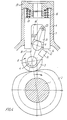
- a reversible two-stroke Diesel engine not shown in detail in the drawings comprises a control shaft 1 rotating in synchronism with the engine crankshaft and to which there are secured actuating cams 2, one for each of the fuel pumps (not shown) of the engine.
- Each cam 2 cooperates with a follower roller 3, which by means of a pin 4 is journalled for rotation in the lower, bifurcated end of an arm 5.
- a pin 6 arm 5 is pivotally journalled in a roller guide 7, which comprises a cylindric skirt 8 that serves for guiding the roller guide for vertical movement relative to a housing 9 secured to the frame (not shown) of the engine.
- control shaft 1 is supported in housing 9 at suitable locations along its length.
- roller guide 7 On the lower side of roller guide 7 there are formed opposed abutment surfaces 13 and 14, respectively, each of which determines, together with one of the abutment surfaces on arm 5, one end position of the pivoting movement of the arm relative to the roller guide.
- Fig. 1 shows arm 5 in that position in which surfaces 12 and 14 abut against one another corresponding to the control shaft 1 rotating anticlockwise, as shown by an arrow on cam 2.
- roller guide 7 is formed with an upwardly extending central stem 18 which at its upper end is guided in cover 17 and in the upwardly facing end face of which there is a recess 19 for coupling the roller guide to the plunger (not shown) of the fuel pump in a known manner (a la bayonet lock).
- Fig. 4 shows the parts of the mechanism in the opposite end position of arm 5 which position is symmetric with that of Fig. 1 about the longitudinal axis of roller guide 7, and which corresponds to the opposite direction of rotation of the engine's crankshaft and control shaft.
- Fig. 4 also shows an upwardly directed extension 21 of arm 5 in which there is secured a pin 22 which engages with a lateral clearance in an elongate vertical groove 23 in a slide 24, see also Figs. 2 and 3.
- Slide 24 is secured to a horizontal rod 25 which is slidably supported in housing 9 and which at one of its ends is adapted to be connected to an element (not shown) by means of which the rod can be moved horizontally between two end positions so as to pivot, via pin 22, arm 5 between the two end positions of that arm described above.
- Said element for moving rod 25 may e.g. be a pneumatic or hydraulic ram or a rotatable shaft extending along the engine and connected to the respective rods 25 by means of links.
- the invention is equally applicable in engines having piston contolled inlet and outlet ports in the cylinder wall and in uniflow scavenge engines having an exhaust valve which, in particular in connection with constant pressure turbocharging, can be actuated by a symmetric or substantially symmetric cam which does not require any change of the angular relationship between the crankshaft and the control shaft when the engine is to be reversed.
Landscapes
- Engineering & Computer Science (AREA)
- Chemical & Material Sciences (AREA)
- Combustion & Propulsion (AREA)
- Mechanical Engineering (AREA)
- General Engineering & Computer Science (AREA)
- Fuel-Injection Apparatus (AREA)
- Transmission Devices (AREA)
Applications Claiming Priority (2)
| Application Number | Priority Date | Filing Date | Title |
|---|---|---|---|
| DK2016/81 | 1981-05-06 | ||
| DK201681A DK147186C (da) | 1981-05-06 | 1981-05-06 | Drivmekanisme for en braendselspumpe til en omstyrbar totaktsmotor |
Publications (3)
| Publication Number | Publication Date |
|---|---|
| EP0065353A2 EP0065353A2 (en) | 1982-11-24 |
| EP0065353A3 EP0065353A3 (en) | 1983-06-08 |
| EP0065353B1 true EP0065353B1 (en) | 1985-08-07 |
Family
ID=8109487
Family Applications (1)
| Application Number | Title | Priority Date | Filing Date |
|---|---|---|---|
| EP82301918A Expired EP0065353B1 (en) | 1981-05-06 | 1982-04-14 | A drive mechanism for a fuel pump of a reversible two-stroke engine |
Country Status (10)
| Country | Link |
|---|---|
| US (1) | US4488452A (OSRAM) |
| EP (1) | EP0065353B1 (OSRAM) |
| JP (1) | JPS57183560A (OSRAM) |
| KR (1) | KR880000478B1 (OSRAM) |
| AR (1) | AR227590A1 (OSRAM) |
| BR (1) | BR8202591A (OSRAM) |
| DE (1) | DE3265184D1 (OSRAM) |
| DK (1) | DK147186C (OSRAM) |
| ES (1) | ES8305882A1 (OSRAM) |
| SU (1) | SU1123552A3 (OSRAM) |
Families Citing this family (13)
| Publication number | Priority date | Publication date | Assignee | Title |
|---|---|---|---|---|
| JPS59128970A (ja) * | 1983-01-14 | 1984-07-25 | Mitsubishi Heavy Ind Ltd | 燃料噴射ポンプ駆動装置 |
| US4498793A (en) * | 1983-05-12 | 1985-02-12 | Printronix, Inc. | Printer shuttle drive having castered cam followers |
| DE3614281A1 (de) * | 1986-04-26 | 1987-10-29 | Kloeckner Humboldt Deutz Ag | Verstelleinrichtung fuer foerderbeginn und steuerzeiten einer brennkraftmaschine |
| JPH0234469Y2 (OSRAM) * | 1986-10-03 | 1990-09-17 | ||
| FR2789616B1 (fr) * | 1999-02-12 | 2001-04-27 | Genus Technologies | Dispositif de deplacement en translation |
| JP4261412B2 (ja) * | 2004-04-16 | 2009-04-30 | 株式会社日立製作所 | 内燃機関の燃料供給装置 |
| DE102006004935A1 (de) | 2005-04-01 | 2006-10-19 | Schaeffler Kg | Variabler Ventiltrieb zur Veränderung von Steuerzeiten nockenbetätigter Gaswechselventile |
| DE102006045933A1 (de) * | 2006-09-28 | 2008-04-03 | Robert Bosch Gmbh | Stößelbaugruppe für eine Hochdruckpumpe und Hochdruckpumpe mit wenigstens einer Stößelbaugruppe |
| DE102014218489A1 (de) * | 2014-09-15 | 2016-03-17 | Robert Bosch Gmbh | Kolbenpumpe |
| GB2533610A (en) * | 2014-12-22 | 2016-06-29 | Gm Global Tech Operations Llc | Fuel unit pump and internal combustion engine comprising it |
| US10113453B2 (en) * | 2015-04-24 | 2018-10-30 | Randy Wayne McReynolds | Multi-fuel compression ignition engine |
| EP3808968B1 (en) | 2019-10-16 | 2025-05-21 | Volvo Car Corporation | A vehicle engine comprising an arrangement for transferring force from a camshaft to an output device |
| KR102631597B1 (ko) * | 2023-06-29 | 2024-02-02 | 주식회사 리플로그 | 엽록소 형광값을 이용한 딸기의 스트레스 지수 산출방법 및 재배관리 시스템 |
Family Cites Families (7)
| Publication number | Priority date | Publication date | Assignee | Title |
|---|---|---|---|---|
| AT27660B (de) * | 1905-06-16 | 1907-02-25 | Richard Freund | Umsteuerung für Kraftmaschinen. |
| GB191014091A (en) * | 1910-06-10 | 1911-03-16 | Arnold Lack | Improvements in Reversing Mechanism for Internal Combustion Engines. |
| US1294077A (en) * | 1917-12-06 | 1919-02-11 | William L Kann | Operation of fuel spraying or injections valve for internal-combustion engines. |
| GB233245A (en) * | 1924-10-30 | 1925-05-07 | Ansaldo Societa Anonima | Device for controlling the operation of the spraying needle in diesel motors |
| CH146351A (de) * | 1929-06-22 | 1931-04-15 | Sulzer Ag | Steuerung für umsteuerbare Einspritzbrennkraftmaschinen, die mit Druckluft angelassen werden. |
| US2599479A (en) * | 1946-02-06 | 1952-06-03 | Petersen Ove | Reversing arrangement in two-stroke engines |
| GB1328096A (en) * | 1969-12-09 | 1973-08-30 | Simms Group Research Dev Ltd | Fuel injection pumps |
-
1981
- 1981-05-06 DK DK201681A patent/DK147186C/da active
-
1982
- 1982-04-14 EP EP82301918A patent/EP0065353B1/en not_active Expired
- 1982-04-14 DE DE8282301918T patent/DE3265184D1/de not_active Expired
- 1982-04-16 US US06/369,143 patent/US4488452A/en not_active Expired - Lifetime
- 1982-04-27 JP JP57069730A patent/JPS57183560A/ja active Granted
- 1982-05-04 KR KR8201948A patent/KR880000478B1/ko not_active Expired
- 1982-05-05 BR BR8202591A patent/BR8202591A/pt not_active IP Right Cessation
- 1982-05-05 SU SU823430750A patent/SU1123552A3/ru active
- 1982-05-05 ES ES511944A patent/ES8305882A1/es not_active Expired
- 1982-05-05 AR AR289314A patent/AR227590A1/es active
Also Published As
| Publication number | Publication date |
|---|---|
| KR830010292A (ko) | 1983-12-30 |
| JPS6151663B2 (OSRAM) | 1986-11-10 |
| KR880000478B1 (ko) | 1988-04-07 |
| US4488452A (en) | 1984-12-18 |
| SU1123552A3 (ru) | 1984-11-07 |
| DK147186B (da) | 1984-05-07 |
| BR8202591A (pt) | 1983-04-19 |
| DK147186C (da) | 1984-10-29 |
| DE3265184D1 (en) | 1985-09-12 |
| EP0065353A2 (en) | 1982-11-24 |
| AR227590A1 (es) | 1982-11-15 |
| EP0065353A3 (en) | 1983-06-08 |
| ES511944A0 (es) | 1983-04-16 |
| DK201681A (da) | 1982-11-07 |
| ES8305882A1 (es) | 1983-04-16 |
| JPS57183560A (en) | 1982-11-11 |
Similar Documents
| Publication | Publication Date | Title |
|---|---|---|
| EP0065353B1 (en) | A drive mechanism for a fuel pump of a reversible two-stroke engine | |
| KR101332561B1 (ko) | 왕복형 내연기관 | |
| US5186130A (en) | Camshaft control device | |
| EP0515528A1 (en) | CAM MECHANISMS. | |
| JP3431144B2 (ja) | 回転及び往復運動の相互接続 | |
| US5359908A (en) | System for reversibly transforming rotary motion into self-guided rectilinear motion | |
| NL8601312A (nl) | Zuigermotor met evenwijdige rond de drijfas geplaatste cylinders. | |
| US4829949A (en) | Valve mechanism for an internal combustion engine | |
| RU2562901C1 (ru) | Направляющее устройство для поршневого механизма и способ | |
| JP2018150938A5 (OSRAM) | ||
| KR20160060581A (ko) | 가변 밸브 기어 | |
| EP1697619B1 (en) | Variable valve gear | |
| GB2406614A (en) | Variable compression ratio i.c. engine | |
| JP4345616B2 (ja) | エンジンの可変動弁装置 | |
| RU1838642C (ru) | Поршневой двигатель внутреннего сгорани | |
| US6761137B2 (en) | Reciprocating piston internal combustion engine | |
| GB2030213A (en) | Opposed piston engine | |
| CN209011947U (zh) | 一种发动机传动装置 | |
| US20080105228A9 (en) | Guide systems for variable valve controller | |
| JPS5819866B2 (ja) | 2シリンダ−式コンクリ−トポンプに利用する揺動スリ−ブ弁 | |
| RU2827286C1 (ru) | Шатунно-поршневая группа | |
| US11473453B1 (en) | Integrated flywheel and intake cam lobe | |
| RU2344300C2 (ru) | Поршневая машина | |
| RU2023895C1 (ru) | Двигатель внутреннего сгорания | |
| RU2153947C2 (ru) | Пресс гидравлический выкрутной |
Legal Events
| Date | Code | Title | Description |
|---|---|---|---|
| PUAI | Public reference made under article 153(3) epc to a published international application that has entered the european phase |
Free format text: ORIGINAL CODE: 0009012 |
|
| AK | Designated contracting states |
Designated state(s): BE CH DE FR GB LI SE |
|
| PUAL | Search report despatched |
Free format text: ORIGINAL CODE: 0009013 |
|
| AK | Designated contracting states |
Designated state(s): BE CH DE FR GB LI SE |
|
| 17P | Request for examination filed |
Effective date: 19831026 |
|
| GRAA | (expected) grant |
Free format text: ORIGINAL CODE: 0009210 |
|
| AK | Designated contracting states |
Designated state(s): BE CH DE FR GB LI SE |
|
| REF | Corresponds to: |
Ref document number: 3265184 Country of ref document: DE Date of ref document: 19850912 |
|
| ET | Fr: translation filed | ||
| BECN | Be: change of holder's name |
Effective date: 19850807 |
|
| REG | Reference to a national code |
Ref country code: CH Ref legal event code: PFA Free format text: M.A.N.-B&W DIESEL A/S |
|
| PLBE | No opposition filed within time limit |
Free format text: ORIGINAL CODE: 0009261 |
|
| STAA | Information on the status of an ep patent application or granted ep patent |
Free format text: STATUS: NO OPPOSITION FILED WITHIN TIME LIMIT |
|
| 26N | No opposition filed | ||
| PGFP | Annual fee paid to national office [announced via postgrant information from national office to epo] |
Ref country code: GB Payment date: 19930315 Year of fee payment: 12 Ref country code: CH Payment date: 19930315 Year of fee payment: 12 |
|
| PGFP | Annual fee paid to national office [announced via postgrant information from national office to epo] |
Ref country code: BE Payment date: 19930316 Year of fee payment: 12 |
|
| PGFP | Annual fee paid to national office [announced via postgrant information from national office to epo] |
Ref country code: FR Payment date: 19930317 Year of fee payment: 12 |
|
| PGFP | Annual fee paid to national office [announced via postgrant information from national office to epo] |
Ref country code: SE Payment date: 19930322 Year of fee payment: 12 |
|
| PG25 | Lapsed in a contracting state [announced via postgrant information from national office to epo] |
Ref country code: GB Effective date: 19940414 |
|
| PG25 | Lapsed in a contracting state [announced via postgrant information from national office to epo] |
Ref country code: SE Effective date: 19940415 |
|
| PG25 | Lapsed in a contracting state [announced via postgrant information from national office to epo] |
Ref country code: LI Effective date: 19940430 Ref country code: CH Effective date: 19940430 Ref country code: BE Effective date: 19940430 |
|
| BERE | Be: lapsed |
Owner name: MAN - B & W DIESEL A/S Effective date: 19940430 |
|
| GBPC | Gb: european patent ceased through non-payment of renewal fee |
Effective date: 19940414 |
|
| PG25 | Lapsed in a contracting state [announced via postgrant information from national office to epo] |
Ref country code: FR Effective date: 19941229 |
|
| REG | Reference to a national code |
Ref country code: CH Ref legal event code: PL |
|
| EUG | Se: european patent has lapsed |
Ref document number: 82301918.7 Effective date: 19941110 |
|
| REG | Reference to a national code |
Ref country code: FR Ref legal event code: ST |
|
| PGFP | Annual fee paid to national office [announced via postgrant information from national office to epo] |
Ref country code: DE Payment date: 20010421 Year of fee payment: 20 |