EP0064112B1 - Rundballenpresse - Google Patents
Rundballenpresse Download PDFInfo
- Publication number
- EP0064112B1 EP0064112B1 EP19810400714 EP81400714A EP0064112B1 EP 0064112 B1 EP0064112 B1 EP 0064112B1 EP 19810400714 EP19810400714 EP 19810400714 EP 81400714 A EP81400714 A EP 81400714A EP 0064112 B1 EP0064112 B1 EP 0064112B1
- Authority
- EP
- European Patent Office
- Prior art keywords
- press
- bale
- products
- conveyor screw
- conveyor
- Prior art date
- Legal status (The legal status is an assumption and is not a legal conclusion. Google has not performed a legal analysis and makes no representation as to the accuracy of the status listed.)
- Expired
Links
- 230000006835 compression Effects 0.000 claims description 16
- 238000007906 compression Methods 0.000 claims description 16
- 238000012546 transfer Methods 0.000 claims description 7
- 230000015572 biosynthetic process Effects 0.000 claims description 6
- 238000004804 winding Methods 0.000 claims description 6
- 230000007246 mechanism Effects 0.000 claims description 3
- 230000005540 biological transmission Effects 0.000 claims description 2
- 238000005096 rolling process Methods 0.000 claims 1
- 238000009826 distribution Methods 0.000 description 5
- 230000000694 effects Effects 0.000 description 4
- 241001124569 Lycaenidae Species 0.000 description 3
- 238000003306 harvesting Methods 0.000 description 3
- 238000009825 accumulation Methods 0.000 description 2
- 230000008878 coupling Effects 0.000 description 2
- 238000010168 coupling process Methods 0.000 description 2
- 238000005859 coupling reaction Methods 0.000 description 2
- 238000012986 modification Methods 0.000 description 2
- 230000004048 modification Effects 0.000 description 2
- 239000010902 straw Substances 0.000 description 2
- 230000006978 adaptation Effects 0.000 description 1
- 210000000078 claw Anatomy 0.000 description 1
- 239000004020 conductor Substances 0.000 description 1
- 230000007547 defect Effects 0.000 description 1
- 238000013461 design Methods 0.000 description 1
- 239000004459 forage Substances 0.000 description 1
- 238000004519 manufacturing process Methods 0.000 description 1
- 238000000034 method Methods 0.000 description 1
- 238000003825 pressing Methods 0.000 description 1
- 238000012549 training Methods 0.000 description 1
Images

Classifications
-
- A—HUMAN NECESSITIES
- A01—AGRICULTURE; FORESTRY; ANIMAL HUSBANDRY; HUNTING; TRAPPING; FISHING
- A01F—PROCESSING OF HARVESTED PRODUCE; HAY OR STRAW PRESSES; DEVICES FOR STORING AGRICULTURAL OR HORTICULTURAL PRODUCE
- A01F15/00—Baling presses for straw, hay or the like
- A01F15/08—Details
- A01F15/10—Feeding devices for the crop material e.g. precompression devices
- A01F15/106—Feeding devices for the crop material e.g. precompression devices for round balers
-
- A—HUMAN NECESSITIES
- A01—AGRICULTURE; FORESTRY; ANIMAL HUSBANDRY; HUNTING; TRAPPING; FISHING
- A01D—HARVESTING; MOWING
- A01D89/00—Pick-ups for loaders, chaff-cutters, balers, field-threshers, or the like, i.e. attachments for picking-up hay or the like field crops
- A01D89/006—Accessories
- A01D89/008—Devices cooperating with the pick-up
Definitions
- the present invention relates to cylindrical or round balers of the type in which a collector mounted at the front of the baler collects from the ground crop products generally arranged in swaths and transfers them to a bale forming chamber. in which the sheet of crop products from the pickup, generally compressed between two rollers, undergoes a winding movement between sets of endless belts or belts driven positively, the bale being, after its formation, ejected from the press through a back door.
- the existing balers are equipped with a pickup whose width corresponds substantially to that of the press, in order to collect for the formation of a bale the products constituting a swath.
- the current trend in the design of agricultural machinery corresponds to an increase in output and consequently to an increase in the size of the machines. This is the case, especially for combine harvesters.
- the object of the invention is to provide a solution to the problem thus posed.
- the invention is embodied in a baler of the type mentioned above characterized in that it comprises a pick-up having a width significantly greater than the width of the body of the press and above and towards the rear of which is mounted a transverse double-threaded conveyor screw achieving convergence of the harvested products, this conveyor screw being arranged and arranged so that the products concentrated by it are transferred directly from said screw inside the press bale forming chamber.
- the invention also solves this problem because the product concentration screw provided behind the pick-up will have the effect of loading the lateral parts of the bale forming chamber to a greater degree than the central part, makes direct transfer of products from the screw to this bale forming chamber, which in fact ensures compensation for the aforementioned defect and provides a more uniform transverse distribution in the press chamber, without the driver having to do progress it along a winding path as previously indicated.
- the conveyor screw is arranged in such a way that the zone for the exit of the products from this screw is immediately adjacent to the deflection roller before this lower conveyor, so that the products concentrated by the screw are taken up directly by said lower conveyor for the formation of the bale.
- the conveyor screw can, if rollers for compression of the sheet of products are provided, occupy a position such that its outlet zone is located just in front of the commissure formed between these compression rollers.
- the conveyor screw is integrated into the outline of the front part of the press.
- the length of the conveyor screw is judiciously substantially equal to the width of the pick-up.
- the transverse conveyor screw is combined with a cover which at least partially covers its upper part and which extends rearwards and downwards to provide an exit zone in the form of a slot situated opposite the upper strand. of the lower press conveyor or of the commissure between the rollers ensuring the compression of the harvested products into a sheet.
- This cover extends down to a level such that it covers for the most part the upper compression roller of the press, which avoids with certainty any entrainment of the harvested products by the thread of the screw and their escape in an area making it possible for them to pass over this upper compression roller, under conditions which would result in a jam in the body of the press in front of the anterior bands or belts, with as a result a stoppage of work.
- the products are on the contrary directed positively towards the lower conveyor of the press or the commissure between the compression rollers, which is of increased interest due to the increase in the flow rate of the products of harvest reaching the press due to the increase in the effective width of the pick-up.
- the rotary drive of the conveyor screw can take place from the mechanisms of the press also ensuring the drive of the conveyor belts or belts used to form the bale.
- the arrangement of the threads on the conveyor screw or the profile thereof is judiciously studied so as to obtain an output of the products from the screw over the entire width of the press, according to a distribution as uniform as possible, this which also provides a solution to the difficulties that may result from a lack of uniformity in the distribution of the products over the width of the press and consequently of a difference in density or diameter over the length of the bale being formed.
- An arrangement according to the invention seems particularly advantageous for collecting straw, which can be distributed on the ground in strips of large width, for example in the case of combine harvesters of large width.
- the body 1 of a conventional type cylindrical or round baler is generally designated by the reference 1, which is supported by wheels 2.
- the press is intended to be coupled in the usual way to a towing vehicle by a drawbar or a drawbar 3.
- the conveyor belt at the press is indicated at 4 and at 5 the conjugate front idler roller.
- the reference 6 designates the upper compression roller which, in known manner, is provided so as to cooperate with the lower roller 5 and with the strip 4 to compress the harvested products picked up on the field by a picker 7 into a specified ply in 8, which undergoes under the effect of bands or belts driven in rotation a winding on itself, in order to form a cylindrical bale 9.
- the bands or belts before, which are passed on a lower deflection roller, have been indicated in 10 11.
- the pick-up 7 of the press has a width clearly greater than that of the body 1 of this press.
- a transverse conveyor screw 12 with a converging effect which comprises a core 13 and a double helical thread 14 provided towards the ends of the conveyor screw, as well as teeth or middle claws 15.
- the conveyor screw extends substantially over the same transverse distance as the pick-up 7. It is rotated, as shown diagrammatically in FIG. 1, by means of a chain 16 passing over a pinion 17 provided at the end of the core 13 of the conveyor screw and on another pinion 18 which is itself driven from the mechanism of the press ensuring the driving of the bands or belts causing the formation of the ball.
- This chain transmission is suitably housed in a casing 19 provided at one end of the conveyor screw 12.
- the conveyor screw 12 is arranged above the pick-up 7, towards the rear part thereof and just in front of the compression rollers 6, 5.
- the height position of this conveyor screw is such that its double thread is substantially tangent to the direction of the flow of harvested products picked up on the field by the picker 7 and transferred to the compression rollers 6, 5.
- the conveyor screw 12 directly directs this flow of products to the corner formed between the compression rollers 6 5 and we see in Fig. 1 that it is immediately adjacent to these compression rollers, so that the products which leave it reach this commissure by a minimum path.
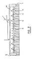
- the transverse conveyor screw 12 is surrounded closely, on a part of its periphery, by a cover 20 which, as visible in FIG. 1, can be fixed on the drawbar 3 towards its upper part, while its lower edge is located just above the commissure formed between the rollers 6 and 5, in order to guide with certainty the flow of harvested products towards this commissure and to oppose any escape or any passage of said products above the roller 6, which would cause jams likely to be the cause of a stop of the press.
- the cover 20 has been indicated in phantom in FIG. 2.
- the cylindrical baler which is the subject of the invention is capable, during its progression behind a tractor vehicle, of picking up harvesting products lying on a field, for example of the straw, over a very wide area, significantly greater than the width of the press body. These products are then directed by the convergence effect exerted by the double thread conveyor screw towards the central part of the pick-up, and they are then transferred by the teeth of this conveyor screw directly into the commissure formed between the rollers 6 and 5, with a view to their compression into a sheet intended to form the bale, any escape being avoided by the cover 20.
Landscapes
- Life Sciences & Earth Sciences (AREA)
- Environmental Sciences (AREA)
- Apparatuses For Bulk Treatment Of Fruits And Vegetables And Apparatuses For Preparing Feeds (AREA)
- Harvester Elements (AREA)
Claims (8)
Priority Applications (4)
| Application Number | Priority Date | Filing Date | Title |
|---|---|---|---|
| EP19810400714 EP0064112B1 (de) | 1981-05-06 | 1981-05-06 | Rundballenpresse |
| DE1981400714 DE64112T1 (de) | 1981-05-06 | 1981-05-06 | Rundballenpresse. |
| DE8181400714T DE3167407D1 (en) | 1981-05-06 | 1981-05-06 | Rotary baler |
| AU83295/82A AU549636B2 (en) | 1981-05-06 | 1982-05-05 | Cylindrical baler pickup |
Applications Claiming Priority (1)
| Application Number | Priority Date | Filing Date | Title |
|---|---|---|---|
| EP19810400714 EP0064112B1 (de) | 1981-05-06 | 1981-05-06 | Rundballenpresse |
Publications (2)
| Publication Number | Publication Date |
|---|---|
| EP0064112A1 EP0064112A1 (de) | 1982-11-10 |
| EP0064112B1 true EP0064112B1 (de) | 1984-11-28 |
Family
ID=8188513
Family Applications (1)
| Application Number | Title | Priority Date | Filing Date |
|---|---|---|---|
| EP19810400714 Expired EP0064112B1 (de) | 1981-05-06 | 1981-05-06 | Rundballenpresse |
Country Status (3)
| Country | Link |
|---|---|
| EP (1) | EP0064112B1 (de) |
| AU (1) | AU549636B2 (de) |
| DE (2) | DE3167407D1 (de) |
Cited By (4)
| Publication number | Priority date | Publication date | Assignee | Title |
|---|---|---|---|---|
| US4470247A (en) * | 1983-05-25 | 1984-09-11 | Sperry Corporation | Round bale forming machine |
| FR2555857A1 (fr) * | 1983-12-01 | 1985-06-07 | Lely Nv C Van Der | Procede pour former des balles de vegetaux ainsi que dispositif et agrafe pour la mise en oeuvre de ce procede |
| US5848523A (en) * | 1996-04-27 | 1998-12-15 | Deere & Company | Crop feed arrangement |
| US10405496B2 (en) * | 2013-10-24 | 2019-09-10 | Kuhn-Geldrop Bv | Open throat intake for a baler |
Families Citing this family (11)
| Publication number | Priority date | Publication date | Assignee | Title |
|---|---|---|---|---|
| GB2203687B (en) | 1987-04-15 | 1990-12-19 | Deere & Co | Pick-up assembly, and baling machine |
| WO1994010828A1 (en) * | 1992-11-06 | 1994-05-26 | Brian Stewart Taege | An improved round baler |
| DE29611444U1 (de) * | 1996-07-01 | 1996-09-05 | Greenland N.V., Nieuw-Vennep | Ballenpresse |
| CA2349381A1 (en) * | 2000-06-15 | 2001-12-15 | Deere & Company | Anti-wrap deflector associated with crop centering auger |
| DE10251827A1 (de) * | 2002-11-07 | 2004-06-09 | Deere & Company, Moline | Gutaufnehmer |
| US6948300B1 (en) | 2003-07-30 | 2005-09-27 | Vermeer Manufacturing Company | Wide pickup header for a round baler |
| JP2006050929A (ja) * | 2004-08-11 | 2006-02-23 | Takakita Co Ltd | 集草装置を備えたロールベーラ装置 |
| FR2899429B1 (fr) * | 2006-04-05 | 2010-04-02 | Sofibrie | Ramasseur comportant un ensemble a barre de coupe escamotable, pour ensileuse |
| PL2387872T3 (pl) | 2010-05-20 | 2016-09-30 | Jednostka tnąca | |
| US8381503B2 (en) | 2011-05-31 | 2013-02-26 | Cnh Canada, Ltd. | Intermeshed feeding system for round balers |
| HUE040510T2 (hu) | 2016-04-11 | 2019-03-28 | Kverneland Group Ravenna Srl | Egység mezõgazdasági termékek szállítására |
Family Cites Families (7)
| Publication number | Priority date | Publication date | Assignee | Title |
|---|---|---|---|---|
| DE1065652B (de) * | 1959-09-17 | |||
| GB685224A (en) * | 1950-04-25 | 1952-12-31 | Victor John Stephens | Improvements in or relating to agricultural pick-up balers |
| US2893537A (en) * | 1957-01-08 | 1959-07-07 | Ford Motor Co | Crop pickup mechanism |
| CH381006A (de) * | 1959-09-03 | 1964-08-15 | Speiser W Fa | Erntemaschine, insbesondere Feldhäcksler |
| DE2523404A1 (de) * | 1975-05-27 | 1976-12-16 | Georg Weiss | Heustrickwickelpresskombinationen |
| FR2315213A7 (fr) * | 1975-06-18 | 1977-01-14 | Taarup As Maskinfab | Machine pour ramasser et/ou recolter des produits agricoles, notamment le foin et les fourrages verts |
| FR2383598A1 (fr) * | 1977-03-16 | 1978-10-13 | Savoie Pierre | Perfectionnement aux procedes et aux machines de mise en balle de paille en vue de leur adaptation a la mise en balle d'andains de tiges de lin |
-
1981
- 1981-05-06 DE DE8181400714T patent/DE3167407D1/de not_active Expired
- 1981-05-06 DE DE1981400714 patent/DE64112T1/de active Pending
- 1981-05-06 EP EP19810400714 patent/EP0064112B1/de not_active Expired
-
1982
- 1982-05-05 AU AU83295/82A patent/AU549636B2/en not_active Ceased
Cited By (4)
| Publication number | Priority date | Publication date | Assignee | Title |
|---|---|---|---|---|
| US4470247A (en) * | 1983-05-25 | 1984-09-11 | Sperry Corporation | Round bale forming machine |
| FR2555857A1 (fr) * | 1983-12-01 | 1985-06-07 | Lely Nv C Van Der | Procede pour former des balles de vegetaux ainsi que dispositif et agrafe pour la mise en oeuvre de ce procede |
| US5848523A (en) * | 1996-04-27 | 1998-12-15 | Deere & Company | Crop feed arrangement |
| US10405496B2 (en) * | 2013-10-24 | 2019-09-10 | Kuhn-Geldrop Bv | Open throat intake for a baler |
Also Published As
| Publication number | Publication date |
|---|---|
| AU8329582A (en) | 1982-11-11 |
| AU549636B2 (en) | 1986-02-06 |
| DE3167407D1 (en) | 1985-01-10 |
| EP0064112A1 (de) | 1982-11-10 |
| DE64112T1 (de) | 1983-05-26 |
Similar Documents
| Publication | Publication Date | Title |
|---|---|---|
| EP0064112B1 (de) | Rundballenpresse | |
| CA2199165C (en) | Crop feed arrangement | |
| US6874311B2 (en) | Crop recovery machine | |
| BE1007190A5 (fr) | Machine de recolte pour former des balles rondes. | |
| EP0149368B1 (de) | Rundballenpresse | |
| FR2627944A1 (fr) | Groupeur d'andains | |
| FR2567714A1 (fr) | Presse de formation de balles enroulees en paille ou produits agricoles analogues | |
| US5097760A (en) | Powered trash removal apparatus for round baler | |
| EP0150630B1 (de) | Rundballenpresse | |
| FR3012287B1 (fr) | Alimentation directe pour presse a balles | |
| FR2559996A1 (fr) | Ramasseuse-hacheuse | |
| US5080009A (en) | Round baler having trash discharge mechanism | |
| EP0064116B1 (de) | Ohne Unterbrechung arbeitende Rundballenpresse | |
| EP0298798A2 (de) | Vorrichtung zur Verkleinerung der Breite der Schwade eines landwirtschaftlichen Sammlers | |
| FR2783131A1 (fr) | Presse a balles rondes avec enrubanneuse integree | |
| FR2485326A1 (fr) | Moissonneuse, notamment du type ramasseuse-hacheuse | |
| EP4042857B1 (de) | Landwirtschaftlicher mäher | |
| EP0150631B1 (de) | Rundballenpresse mit Antrieb der Anlaufrolle | |
| US7311040B2 (en) | Cylindrical baling press | |
| EP3289855B1 (de) | Ausstreichwalzenkappensystem | |
| EP0131078B1 (de) | Rollballenpresse mit Mähwerk | |
| US5408925A (en) | Trash removal apparatus for a round baler | |
| EP0074451B1 (de) | Erntekonditioniermaschine, wie z.B. Mäh- und Konditioniereinrichtung oder Aufnahme- und Konditioniereinrichtung | |
| FR2560736A1 (fr) | Machine a recolter des tomates | |
| FR2559344A1 (fr) | Machine a recolter le fourrage avec transport lateral |
Legal Events
| Date | Code | Title | Description |
|---|---|---|---|
| PUAI | Public reference made under article 153(3) epc to a published international application that has entered the european phase |
Free format text: ORIGINAL CODE: 0009012 |
|
| 17P | Request for examination filed |
Effective date: 19820812 |
|
| AK | Designated contracting states |
Designated state(s): AT BE CH DE FR GB IT LU NL SE |
|
| ITCL | It: translation for ep claims filed |
Representative=s name: LENZI & C. |
|
| RBV | Designated contracting states (corrected) |
Designated state(s): DE FR GB IT NL |
|
| TCNL | Nl: translation of patent claims filed | ||
| DET | De: translation of patent claims | ||
| ITF | It: translation for a ep patent filed | ||
| GRAA | (expected) grant |
Free format text: ORIGINAL CODE: 0009210 |
|
| AK | Designated contracting states |
Designated state(s): DE FR GB IT NL |
|
| REF | Corresponds to: |
Ref document number: 3167407 Country of ref document: DE Date of ref document: 19850110 |
|
| PLBI | Opposition filed |
Free format text: ORIGINAL CODE: 0009260 |
|
| 26 | Opposition filed |
Opponent name: CLAAS OHG Effective date: 19850219 |
|
| PLBI | Opposition filed |
Free format text: ORIGINAL CODE: 0009260 |
|
| NLR1 | Nl: opposition has been filed with the epo |
Opponent name: CLAAS OHG. |
|
| 26 | Opposition filed |
Opponent name: GEBRUEDER WELGER GMBH & CO. KG Effective date: 19850801 |
|
| NLR1 | Nl: opposition has been filed with the epo |
Opponent name: GEBRUEDER WELGER GMBH & CO. KG |
|
| PLBN | Opposition rejected |
Free format text: ORIGINAL CODE: 0009273 |
|
| STAA | Information on the status of an ep patent application or granted ep patent |
Free format text: STATUS: OPPOSITION REJECTED |
|
| 27O | Opposition rejected |
Effective date: 19880726 |
|
| NLR2 | Nl: decision of opposition | ||
| ITTA | It: last paid annual fee | ||
| PGFP | Annual fee paid to national office [announced via postgrant information from national office to epo] |
Ref country code: GB Payment date: 19920416 Year of fee payment: 12 |
|
| PG25 | Lapsed in a contracting state [announced via postgrant information from national office to epo] |
Ref country code: GB Effective date: 19930506 |
|
| PGFP | Annual fee paid to national office [announced via postgrant information from national office to epo] |
Ref country code: FR Payment date: 19930513 Year of fee payment: 13 |
|
| PGFP | Annual fee paid to national office [announced via postgrant information from national office to epo] |
Ref country code: NL Payment date: 19930531 Year of fee payment: 13 |
|
| PGFP | Annual fee paid to national office [announced via postgrant information from national office to epo] |
Ref country code: DE Payment date: 19930703 Year of fee payment: 13 |
|
| GBPC | Gb: european patent ceased through non-payment of renewal fee |
Effective date: 19930506 |
|
| PG25 | Lapsed in a contracting state [announced via postgrant information from national office to epo] |
Ref country code: NL Effective date: 19941201 |
|
| NLV4 | Nl: lapsed or anulled due to non-payment of the annual fee | ||
| PG25 | Lapsed in a contracting state [announced via postgrant information from national office to epo] |
Ref country code: FR Effective date: 19950131 |
|
| PG25 | Lapsed in a contracting state [announced via postgrant information from national office to epo] |
Ref country code: DE Effective date: 19950201 |
|
| REG | Reference to a national code |
Ref country code: FR Ref legal event code: ST |
|
| APAH | Appeal reference modified |
Free format text: ORIGINAL CODE: EPIDOSCREFNO |