EP0062676B1 - Vorrichtung zum kontinuierlichen giessen von metalldrähten, röhren und schichten - Google Patents
Vorrichtung zum kontinuierlichen giessen von metalldrähten, röhren und schichten Download PDFInfo
- Publication number
- EP0062676B1 EP0062676B1 EP19810902986 EP81902986A EP0062676B1 EP 0062676 B1 EP0062676 B1 EP 0062676B1 EP 19810902986 EP19810902986 EP 19810902986 EP 81902986 A EP81902986 A EP 81902986A EP 0062676 B1 EP0062676 B1 EP 0062676B1
- Authority
- EP
- European Patent Office
- Prior art keywords
- chill mold
- heat
- metal
- cooler
- casting
- Prior art date
- Legal status (The legal status is an assumption and is not a legal conclusion. Google has not performed a legal analysis and makes no representation as to the accuracy of the status listed.)
- Expired
Links
- 239000002184 metal Substances 0.000 title claims abstract description 32
- 229910052751 metal Inorganic materials 0.000 title claims abstract description 32
- 238000009749 continuous casting Methods 0.000 title claims abstract description 11
- 238000005266 casting Methods 0.000 claims description 17
- 238000001816 cooling Methods 0.000 claims description 11
- ATJFFYVFTNAWJD-UHFFFAOYSA-N Tin Chemical compound [Sn] ATJFFYVFTNAWJD-UHFFFAOYSA-N 0.000 claims description 2
- 238000012546 transfer Methods 0.000 description 17
- 239000000155 melt Substances 0.000 description 8
- 239000002826 coolant Substances 0.000 description 6
- 239000000463 material Substances 0.000 description 6
- 239000007789 gas Substances 0.000 description 4
- 238000000034 method Methods 0.000 description 4
- 238000007711 solidification Methods 0.000 description 3
- 230000008023 solidification Effects 0.000 description 3
- OKTJSMMVPCPJKN-UHFFFAOYSA-N Carbon Chemical compound [C] OKTJSMMVPCPJKN-UHFFFAOYSA-N 0.000 description 2
- 230000015572 biosynthetic process Effects 0.000 description 2
- 230000008602 contraction Effects 0.000 description 2
- 239000013078 crystal Substances 0.000 description 2
- 229910002804 graphite Inorganic materials 0.000 description 2
- 239000010439 graphite Substances 0.000 description 2
- 150000003839 salts Chemical class 0.000 description 2
- 239000007787 solid Substances 0.000 description 2
- RYGMFSIKBFXOCR-UHFFFAOYSA-N Copper Chemical compound [Cu] RYGMFSIKBFXOCR-UHFFFAOYSA-N 0.000 description 1
- 229910000881 Cu alloy Inorganic materials 0.000 description 1
- HCHKCACWOHOZIP-UHFFFAOYSA-N Zinc Chemical compound [Zn] HCHKCACWOHOZIP-UHFFFAOYSA-N 0.000 description 1
- 238000009835 boiling Methods 0.000 description 1
- 239000004020 conductor Substances 0.000 description 1
- 229910052802 copper Inorganic materials 0.000 description 1
- 239000010949 copper Substances 0.000 description 1
- 238000013461 design Methods 0.000 description 1
- 238000011161 development Methods 0.000 description 1
- 238000010438 heat treatment Methods 0.000 description 1
- 239000007788 liquid Substances 0.000 description 1
- 238000005259 measurement Methods 0.000 description 1
- 230000001603 reducing effect Effects 0.000 description 1
- 239000011819 refractory material Substances 0.000 description 1
- XLYOFNOQVPJJNP-UHFFFAOYSA-N water Substances O XLYOFNOQVPJJNP-UHFFFAOYSA-N 0.000 description 1
- 239000011701 zinc Substances 0.000 description 1
- 229910052725 zinc Inorganic materials 0.000 description 1
Images
Classifications
-
- B—PERFORMING OPERATIONS; TRANSPORTING
- B22—CASTING; POWDER METALLURGY
- B22D—CASTING OF METALS; CASTING OF OTHER SUBSTANCES BY THE SAME PROCESSES OR DEVICES
- B22D11/00—Continuous casting of metals, i.e. casting in indefinite lengths
- B22D11/04—Continuous casting of metals, i.e. casting in indefinite lengths into open-ended moulds
- B22D11/045—Continuous casting of metals, i.e. casting in indefinite lengths into open-ended moulds for horizontal casting
-
- B—PERFORMING OPERATIONS; TRANSPORTING
- B22—CASTING; POWDER METALLURGY
- B22D—CASTING OF METALS; CASTING OF OTHER SUBSTANCES BY THE SAME PROCESSES OR DEVICES
- B22D11/00—Continuous casting of metals, i.e. casting in indefinite lengths
- B22D11/04—Continuous casting of metals, i.e. casting in indefinite lengths into open-ended moulds
- B22D11/055—Cooling the moulds
Definitions
- the present invention relates to an apparatus for the continuous casting of metal bars, pipes and sheets, comprising a chill mold for receiving the molten metal, a cooling member fitted around the rear part of the chill mold as seen in the withdrawing direction, a refractory lining protecting at least the cooling member, and members for the continuous withdrawing of the bar, pipe or sheet which has solidified in the chill mold-from the chill mold.
- the object of the present invention is to promote the transfer of the heat from the material being cast and thereby to increase the casting rate and obtain a more advantageous crystal structure in the casting, at least when copper or copper alloys are being cast.
- the chill mold may be made of graphite, and during casting the heat transferred from the solidifying molten metal and the solidified metal is directed further to a cooling medium circulating in the cooler. It is very important that this transfer of heat is effective, for it decides the rate at which the continuous casting can be carried out.
- a metal bar, pipe or sheet contracts when solidifying and cooling, and thereby a gap forms between the piece being cast and the chill mold; the gap is known to complicate the transfer of heat from the piece being cast to the chill mold. This gap cannot be completely eliminated because, if it is, then there is the risk that the casting adheres to the chill mold if the mold converges in the withdrawing direction. Owing to the low heat conductivity of air and gases, even a very narrow gap caused by contraction constitutes a considerable obstacle to the transfer of heat.
- the object of the present invention is therefore to provide an apparatus for the continuous casting of metal bars, pipes or sheets, an apparatus in which the transfer of heat from the solidifying melt and the cooling metal piece is more effective than previously so that the casting rate can be increased and simultaneously a product with improved crystal structure can possibly be obtained.
- the gap or gaps between the chill mold and the cooler are filled with a medium having a high thermal conductivity, such as molten metal or molten salt, in which case this gap is advantageously connected to an outside expansion vessel.
- a medium having a high thermal conductivity such as molten metal or molten salt
- a liquid with a high thermal conductivity such as a molten metal
- a liquid with a high thermal conductivity such as a molten metal
- the heat-transferring medium does not come into contact with the metal being cast and, owing to the drop of temperature between the walls of the chill mold, the boiling point of the heat-transferring medium need not necessarily be higher than the solidification point of the metal being cast. Also, there is no fear of leakage problems in this case.
- the molten metal or salt is in a flowing motion, but it can just as well be completely stationary.
- the effectiveness of the heat-transferring medium is based on its thermal conductivity, which is far superior to that of gas, a decisive factor in this connection.
- the heat-transferring material fills as completely as possible the gaps between the chill mold and the cooler so that no gas pockets appear in these spaces. Therefore, it is advantageous to connect the gap or gaps to an expansion vessel for the heat-transferring medium so that heat-transferring medium can flow into the gap or gaps between the chill mold and the cooler and back as the volume of the gaps varies according to the thermal expansion movement of the surrounding walls.
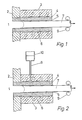
- Figures 1 and 2 depict cross sectional side elevations of two preferred embodiments of the invention.
- the melt to be cast is indicated by reference numeral 1.
- the melt to be cast can be in a melt container the wall of which in general is indicated by 2 and to which a chill mold 4 made of graphite is attached to receive the melt. Outside the container wall 2 there is, fitted around the chill mold 4, a cooler 3, in which ducts for the cooling medium have been made in a known manner.
- the melt 1 flowing into the chill mold 4 yields heat to the walls of the chill mold 4 and forms, at a certain distance from the inlet of the chill mold 4, a solidification front, which is indicated by a dotted line in the drawing.
- the solidified metal is withdrawn in the form of a bar 7 from the chill mold 4 by means of withdrawal members 9.
- the gap 6 between the chill mold 4 and the cooler 3 is connected by means of a pipe 8 to an expansion vessel 10, which is partly filled with a medium which transfers heat well.
- the expansion vessel 10 is at a higher level than the gap 6, in which there thus prevails a metallostatic pressure when molten metal is used as the cooling medium.
- the metal in the expansion vessel can be maintained in a molten state by, for example, fitting a heating resistor around the vessel.
- reference numeral 2 in Figure 1 indicates a refractory lining which prevents the melt from coming into direct contact with the cooler 3, which in this case must be lowered at least partly to a level below the melt surface.
Landscapes
- Engineering & Computer Science (AREA)
- Mechanical Engineering (AREA)
- Continuous Casting (AREA)
Claims (3)
Priority Applications (1)
| Application Number | Priority Date | Filing Date | Title |
|---|---|---|---|
| AT81902986T ATE13826T1 (de) | 1980-10-17 | 1981-10-16 | Vorrichtung zum kontinuierlichen giessen von metalldraehten, roehren und schichten. |
Applications Claiming Priority (2)
| Application Number | Priority Date | Filing Date | Title |
|---|---|---|---|
| FI803270 | 1980-10-17 | ||
| FI803270A FI77586C (fi) | 1980-10-17 | 1980-10-17 | Anordning foer kontinuerlig gjutning av metallstaenger, -roer och -plattor. |
Publications (2)
| Publication Number | Publication Date |
|---|---|
| EP0062676A1 EP0062676A1 (de) | 1982-10-20 |
| EP0062676B1 true EP0062676B1 (de) | 1985-06-19 |
Family
ID=8513858
Family Applications (1)
| Application Number | Title | Priority Date | Filing Date |
|---|---|---|---|
| EP19810902986 Expired EP0062676B1 (de) | 1980-10-17 | 1981-10-16 | Vorrichtung zum kontinuierlichen giessen von metalldrähten, röhren und schichten |
Country Status (3)
| Country | Link |
|---|---|
| EP (1) | EP0062676B1 (de) |
| FI (1) | FI77586C (de) |
| WO (1) | WO1982001332A1 (de) |
Families Citing this family (1)
| Publication number | Priority date | Publication date | Assignee | Title |
|---|---|---|---|---|
| CN104128574B (zh) * | 2014-07-15 | 2016-04-13 | 武汉泛洲中越合金有限公司 | 水平连铸铸造装置 |
Family Cites Families (2)
| Publication number | Priority date | Publication date | Assignee | Title |
|---|---|---|---|---|
| DE876573C (de) * | 1950-06-11 | 1953-05-15 | Siegfried Dr-Ing E H Junghans | Verfahren zum Kuehlen von Giessformen und Giessform zum Ausueben des Verfahrens |
| CH537766A (de) * | 1971-08-30 | 1973-06-15 | Bbc Brown Boveri & Cie | Verfahren und Einrichtung zum kontinuierlichen Giessen oder Ziehen eines insbesondere metallischen Strangkörpers |
-
1980
- 1980-10-17 FI FI803270A patent/FI77586C/fi not_active IP Right Cessation
-
1981
- 1981-10-16 EP EP19810902986 patent/EP0062676B1/de not_active Expired
- 1981-10-16 WO PCT/FI1981/000076 patent/WO1982001332A1/en not_active Ceased
Also Published As
| Publication number | Publication date |
|---|---|
| FI77586B (fi) | 1988-12-30 |
| EP0062676A1 (de) | 1982-10-20 |
| FI77586C (fi) | 1989-04-10 |
| WO1982001332A1 (en) | 1982-04-29 |
| FI803270L (fi) | 1982-04-18 |
Similar Documents
| Publication | Publication Date | Title |
|---|---|---|
| US2225373A (en) | Method and apparatus for casting metal | |
| US3853309A (en) | Components using cast-in cooling tubes | |
| EP1060817B1 (de) | Druckgussverfahren von Magnesiumlegierungen | |
| FI107789B (fi) | Valumuotti jäähdytyselementin valmistamiseksi ja muotissa valmistettu jäähdytyselementti | |
| WO2012154490A1 (en) | Directional solidification furnace heat exchanger | |
| CN206143232U (zh) | 一种高炉出铁沟主沟水冷器件 | |
| EP0062676B1 (de) | Vorrichtung zum kontinuierlichen giessen von metalldrähten, röhren und schichten | |
| JPH08246014A (ja) | 高炉水冷溶滓樋 | |
| JP3993099B2 (ja) | 溶融金属液の高さを測定するスティック | |
| US5595237A (en) | Horizontal continuous casting apparatus for metals | |
| JP2889928B2 (ja) | 磁気浮揚式連続鋳造装置 | |
| CA1285461C (en) | Casting powder for use in bottom pour ingot steel production and method for employing same | |
| JPS6010774Y2 (ja) | アルミニウム連続鋳造用湯溜 | |
| JP2000017313A (ja) | 溶融金属用樋 | |
| CN219724576U (zh) | 一种薄带连铸用布流装置 | |
| JPH03210950A (ja) | 連続鋳造用パウダー | |
| US3293704A (en) | Method and apparatus for the casting of fusible materials | |
| Szekely et al. | The role of natural convection in ladles as affecting tundish temperature control in continuous casting | |
| CN222288739U (zh) | 一种结晶器加热装置 | |
| US3186040A (en) | Method and apparatus for distributing molten metal and the like | |
| SU792702A1 (ru) | Смесь дл заполнени армирующих трубок при заливке их расплавленным сплавом | |
| El-Mahallawy et al. | Aluminium and Al–4· 5Cu alloy end chill: Structural observation and heat flow analysis | |
| SU491811A1 (ru) | Индукционна тигельна печь | |
| JPS59197346A (ja) | 中空鋼塊の製造方法 | |
| SU1668025A1 (ru) | Устройство дл лить под действием перепада давлени |
Legal Events
| Date | Code | Title | Description |
|---|---|---|---|
| PUAI | Public reference made under article 153(3) epc to a published international application that has entered the european phase |
Free format text: ORIGINAL CODE: 0009012 |
|
| 17P | Request for examination filed |
Effective date: 19820617 |
|
| AK | Designated contracting states |
Designated state(s): AT CH DE GB |
|
| GRAA | (expected) grant |
Free format text: ORIGINAL CODE: 0009210 |
|
| AK | Designated contracting states |
Designated state(s): AT CH DE GB LI |
|
| REF | Corresponds to: |
Ref document number: 13826 Country of ref document: AT Date of ref document: 19850715 Kind code of ref document: T |
|
| REF | Corresponds to: |
Ref document number: 3171051 Country of ref document: DE Date of ref document: 19850801 |
|
| PLBE | No opposition filed within time limit |
Free format text: ORIGINAL CODE: 0009261 |
|
| STAA | Information on the status of an ep patent application or granted ep patent |
Free format text: STATUS: NO OPPOSITION FILED WITHIN TIME LIMIT |
|
| 26N | No opposition filed | ||
| PGFP | Annual fee paid to national office [announced via postgrant information from national office to epo] |
Ref country code: AT Payment date: 19860908 Year of fee payment: 6 |
|
| PGFP | Annual fee paid to national office [announced via postgrant information from national office to epo] |
Ref country code: DE Payment date: 19880930 Year of fee payment: 8 |
|
| PG25 | Lapsed in a contracting state [announced via postgrant information from national office to epo] |
Ref country code: GB Effective date: 19891016 Ref country code: AT Effective date: 19891016 |
|
| PG25 | Lapsed in a contracting state [announced via postgrant information from national office to epo] |
Ref country code: LI Effective date: 19891031 Ref country code: CH Effective date: 19891031 |
|
| GBPC | Gb: european patent ceased through non-payment of renewal fee | ||
| REG | Reference to a national code |
Ref country code: CH Ref legal event code: PL |
|
| PG25 | Lapsed in a contracting state [announced via postgrant information from national office to epo] |
Ref country code: DE Effective date: 19900703 |