EP0061698A1 - Vorrichtung mit kreisendem Kolben zum Fördern von Fluiden, mit einer Einrichtung zum Verhindern der Rotation - Google Patents
Vorrichtung mit kreisendem Kolben zum Fördern von Fluiden, mit einer Einrichtung zum Verhindern der Rotation Download PDFInfo
- Publication number
- EP0061698A1 EP0061698A1 EP82102401A EP82102401A EP0061698A1 EP 0061698 A1 EP0061698 A1 EP 0061698A1 EP 82102401 A EP82102401 A EP 82102401A EP 82102401 A EP82102401 A EP 82102401A EP 0061698 A1 EP0061698 A1 EP 0061698A1
- Authority
- EP
- European Patent Office
- Prior art keywords
- orbital
- fixed
- orbiting
- race
- radius
- Prior art date
- Legal status (The legal status is an assumption and is not a legal conclusion. Google has not performed a legal analysis and makes no representation as to the accuracy of the status listed.)
- Granted
Links
- 239000012530 fluid Substances 0.000 title claims abstract description 58
- 238000006073 displacement reaction Methods 0.000 title claims abstract description 25
- 238000005096 rolling process Methods 0.000 claims abstract description 15
- 230000000694 effects Effects 0.000 abstract description 3
- 238000007373 indentation Methods 0.000 description 6
- 238000010276 construction Methods 0.000 description 3
- 230000002093 peripheral effect Effects 0.000 description 3
- 238000006243 chemical reaction Methods 0.000 description 2
- 239000003507 refrigerant Substances 0.000 description 2
- 230000006835 compression Effects 0.000 description 1
- 238000007906 compression Methods 0.000 description 1
- 230000007423 decrease Effects 0.000 description 1
- 230000001419 dependent effect Effects 0.000 description 1
- ZZUFCTLCJUWOSV-UHFFFAOYSA-N furosemide Chemical compound C1=C(Cl)C(S(=O)(=O)N)=CC(C(O)=O)=C1NCC1=CC=CO1 ZZUFCTLCJUWOSV-UHFFFAOYSA-N 0.000 description 1
- 238000003754 machining Methods 0.000 description 1
- 238000004519 manufacturing process Methods 0.000 description 1
- 230000013011 mating Effects 0.000 description 1
- 230000035515 penetration Effects 0.000 description 1
- 238000007789 sealing Methods 0.000 description 1
Images


Classifications
-
- F—MECHANICAL ENGINEERING; LIGHTING; HEATING; WEAPONS; BLASTING
- F16—ENGINEERING ELEMENTS AND UNITS; GENERAL MEASURES FOR PRODUCING AND MAINTAINING EFFECTIVE FUNCTIONING OF MACHINES OR INSTALLATIONS; THERMAL INSULATION IN GENERAL
- F16C—SHAFTS; FLEXIBLE SHAFTS; ELEMENTS OR CRANKSHAFT MECHANISMS; ROTARY BODIES OTHER THAN GEARING ELEMENTS; BEARINGS
- F16C19/00—Bearings with rolling contact, for exclusively rotary movement
- F16C19/50—Other types of ball or roller bearings
-
- F—MECHANICAL ENGINEERING; LIGHTING; HEATING; WEAPONS; BLASTING
- F01—MACHINES OR ENGINES IN GENERAL; ENGINE PLANTS IN GENERAL; STEAM ENGINES
- F01C—ROTARY-PISTON OR OSCILLATING-PISTON MACHINES OR ENGINES
- F01C17/00—Arrangements for drive of co-operating members, e.g. for rotary piston and casing
- F01C17/06—Arrangements for drive of co-operating members, e.g. for rotary piston and casing using cranks, universal joints or similar elements
- F01C17/063—Arrangements for drive of co-operating members, e.g. for rotary piston and casing using cranks, universal joints or similar elements with only rolling movement
-
- F—MECHANICAL ENGINEERING; LIGHTING; HEATING; WEAPONS; BLASTING
- F04—POSITIVE - DISPLACEMENT MACHINES FOR LIQUIDS; PUMPS FOR LIQUIDS OR ELASTIC FLUIDS
- F04C—ROTARY-PISTON, OR OSCILLATING-PISTON, POSITIVE-DISPLACEMENT MACHINES FOR LIQUIDS; ROTARY-PISTON, OR OSCILLATING-PISTON, POSITIVE-DISPLACEMENT PUMPS
- F04C18/00—Rotary-piston pumps specially adapted for elastic fluids
- F04C18/02—Rotary-piston pumps specially adapted for elastic fluids of arcuate-engagement type, i.e. with circular translatory movement of co-operating members, each member having the same number of teeth or tooth-equivalents
- F04C18/0207—Rotary-piston pumps specially adapted for elastic fluids of arcuate-engagement type, i.e. with circular translatory movement of co-operating members, each member having the same number of teeth or tooth-equivalents both members having co-operating elements in spiral form
- F04C18/0215—Rotary-piston pumps specially adapted for elastic fluids of arcuate-engagement type, i.e. with circular translatory movement of co-operating members, each member having the same number of teeth or tooth-equivalents both members having co-operating elements in spiral form where only one member is moving
-
- F—MECHANICAL ENGINEERING; LIGHTING; HEATING; WEAPONS; BLASTING
- F04—POSITIVE - DISPLACEMENT MACHINES FOR LIQUIDS; PUMPS FOR LIQUIDS OR ELASTIC FLUIDS
- F04C—ROTARY-PISTON, OR OSCILLATING-PISTON, POSITIVE-DISPLACEMENT MACHINES FOR LIQUIDS; ROTARY-PISTON, OR OSCILLATING-PISTON, POSITIVE-DISPLACEMENT PUMPS
- F04C2240/00—Components
- F04C2240/80—Other components
- F04C2240/807—Balance weight, counterweight
-
- F—MECHANICAL ENGINEERING; LIGHTING; HEATING; WEAPONS; BLASTING
- F16—ENGINEERING ELEMENTS AND UNITS; GENERAL MEASURES FOR PRODUCING AND MAINTAINING EFFECTIVE FUNCTIONING OF MACHINES OR INSTALLATIONS; THERMAL INSULATION IN GENERAL
- F16C—SHAFTS; FLEXIBLE SHAFTS; ELEMENTS OR CRANKSHAFT MECHANISMS; ROTARY BODIES OTHER THAN GEARING ELEMENTS; BEARINGS
- F16C2360/00—Engines or pumps
- F16C2360/42—Pumps with cylinders or pistons
Definitions
- This invention relates to a rotary fluid apparatus, and more particularly, to an improvement in a rotation preventing/thrust bearing device for an orbiting piston type fluid apparatus.
- An apparatus of one type is a rotary machine as disclosed in U.S. Patent No. 1,906,142 to John Ekelof, which is provided with an annular and eccentrically movable piston adapted to act within an annular cylinder provided with a radial transverse wall.
- One end of wall of the cylinder is fixedly mounted and the other wall consists of a cover disk connected to the annular piston which is driven by a crank shaft.
- Another prior art apparatus of the orbiting piston type is a scroll-type apparatus as shown in U.S. Patents Nos.801,182 and 3,500,119.
- U.S. Patent No. 801,182 discloses a device . including two scroll members each having a circular end plate and a spiroidal or involute spiral element. These scroll members are maintained angularly and radially offset so that both spiral elements interfit to make a plurality of line contacts between their spiral curved surfaces to thereby seal off and define at least one pair of fluid pockets.
- the relative orbital motion of two scroll members shifts the line.contacts along the spiral curved surfaces and, as a result, the volume of the fluid pockets changes. Since the volume of the fluid pockets increases or decreases dependent on the direction of the orbital motion, the scroll-type fluid displacement apparatus is applicable to compress, expand or pump fluids.
- one of scroll members is fixed to a housing and the other scroll member, which is an orbiting scroll member, is eccentrically supported on a crank pin of a rotating shaft to cause orbital motion of the orbiting scroll member.
- the scroll type apparatus also includes a rotation preventing device which prevents rotation of the orbiting scroll member to thereby maintain the two scroll members in a predetermined angular relationship during operation of the apparatus.
- the orbiting scroll in conventional scroll type apparatus is supported on a crank pin in a cantilever manner, an axial slant of this orbiting scroll occurs.
- Axial slant also occurs because the movement of the orbiting scroll is not rotary motion around the center of the scroll, but is orbiting motion caused by the eccentric movement of a crank pin driven by the rotation of the drive shaft.
- Several problem from the occurrence of this axial slant including improper sealing of line contacts, vibration of the apparatus during operation and noise caused by physical striking of the spiral elements.
- a thrust bearing device for carrying the axial loads.
- scroll type fluid displacement apparatus is usually provided with a thrust bearing device within the housing.
- the fixed portion includes (1) an annular fixed race 371' having one end surface fitted against .an axial end surface of annular projection 112' of front end plate 11', and (2) a fixed ring 372' fitted against the other axial end surface of fixed race 371' to extend outwardly therefrom and cover the other end surface of fixed race 371'.
- Fixed race 371' and ring 372' are attached to the axial end surface of annular projection 112' by pins 373'.
- the orbital portion also includes (1) an annular orbital race 374',which has one end surface fitted against an axial end surface of circular plate 271' and (2) an orbital ring 375' fitted against the other axial end surface of orbital race 374' to extend outwardly therefrom and cover the other axial end surface of orbital race 374'.
- An annular orbital race 374' which has one end surface fitted against an axial end surface of circular plate 271' and (2) an orbital ring 375' fitted against the other axial end surface of orbital race 374' to extend outwardly therefrom and cover the other axial end surface of orbital race 374'.
- a small clearance is maintained between the end surface of fixed ring 372' and the end surface of orbital ring 375'.
- Orbital race 374' and ring 375' are attached to the end surface of circular plate 271' by pins 376'.
- Fixed ring 372' and orbital ring 375' each have a plurality of holes or pockets 372a' and 375a' being equal.
- the holes or pockets 372a' on fixed ring 372' correspond to or are a mirror image of the holes or pockets 375a' on orbital ring 375', i.e., each pair of pockets facing each other have the same size and pitch,and the radial distance of the pockets from the center 0 of their respective rings 372' and 375' is the same,i.e., the centers of the pockets are located at the same distance from the center of the rings 372' and 375'.
- Bearing elements, such as balls or spheres 377' are placed between facing generally aligned pairs of pockets 372a' and 375a'
- the radius of pockets 372a' and 375a' are selected the half of the orbital radius Ro.
- the balls 377' are held by the edge of both pairs pockets and moved along the edge of pairs pockets.
- the traveling radius of balls against to fixed race is half of the traveling radius of orbiting scroll in its orbital motion. Therefore, the width of the race must be took longer than the traveling radius of balls.
- An orbiting piston type fluid displacement apparatus includes a housing.
- a fixed member attached to the housing and has first end plate from which a fixed fluid displacement member extends into the interior of the housing.
- An orbiting member has a second end plate from o which an orbiting fluid displacement member extends.
- the fixed and orbiting fluid members interfit at a radial offset to make a line contact to separated a fluid inlet from a fluid outlet.
- a driving mechanism including a drive shaft, which is rotatably supported by the housing, is connected to the orbiting member, to effect the orbital motion of the orbiting fluid displacement member.
- a rotation preventing/thrust bearing device is-connected to the orbiting fluid displacement member for preventing the rotation of the orbiting fluid displacement member during orbital motion so that the line contact moves toward the discharge side during the orbital motion of the orbiting fluid displacement member.
- the rotation preventing/thrust bearing device comprises an orbital portion fixed portion and a plurality of bearings, such as balls or spheres.
- the orbital portion includes an annular race and ring both of which are formed separatly.
- the race is placed within an annular groove formed on an axial end surface of end plate of orbiting member.
- the ring is fitted against the axial end surface of end plate of orbiting member to cover the end surface of the orbital race.
- the fixed portion includes a second annular race and a second ring both of which are formed separatly.
- the second race is placed within an annular groove formed on an axial end surface of the housing to cover the axial end surface of the second race. A clearance is maintained between the ring of orbital portion and the second ring of the fixed portion.
- the fixed ring and orbital ring cach have a plurality of holes or pockets in the axial direction, the number of holes or pockets in each rings being equal.
- the radius of pockets of fixed ring being formed greater than the radius of pockets of orbital ring.
- the bearings are placed between the edge of both facing pockets. The each bearings is permitted to the rolling motion with regard to the orbital race at the radius Rl and also is parmitted the rolling motion with regard to the fixed race at the radius R2.
- the total amount of both radius is made the substancially same the orbital radius of orbiting member.
- the bearings are thus made rolling motion along the edge of both facing pockets.
- the rotation of the orbiting member is prevented by the bearings and the thrust load from the orbiting member is supported by the fixed race through the bearings.
- a fluid displacement apparatus in accordance with the present invention is shown in the form of a scroll type refrigerant compressor unit 1.
- the compressor unit 1 includes compressor housing 10 having a front end plate 11 and cup shaped casing 12 which is attached to an end surface of front end plate 11.
- An opening 111 is formed in the center of front end plate 11 for the penetration or passage of drive shaft 13.
- An annular projection 112 is formed in the rear end surface of front end plate 11 which faces cup shaped casing 12; this annular projection 112 is concentric with opening 111.
- An outer peripheral surface of annular projection 112 bites into an inner wall of the opening of cup shaped casing 12.
- Cup shaped casing 12 is fixed on the rear end surface of front end plate 11 by a fastening device,for example, bolts and nuts,so that the opening of cup shaped casing 12 is covered by front end plate 11.
- An 0-ring 14 is placed between the outer peripheral surface of annular projection 112 and the inner wall of the opening of cup shaped casing -12 to seal the mating surface of front end plate 11 and cup shaped casing 12.
- Front end plate 11 has an annular sleeve 15 projecting from the front end surface thereof which surrounds drive shaft 13 and defines a shaft seal cavity.
- sleeve 15 is separated from front end plate 11; sleeve 15 is fixed to the front end surface of front end plate 11 by screws (not shown).
- An 0-ring 16 is placed between the end surface of front end plate 11 and an end surface of sleeve 15 to seal the surface of front end plate 11 and sleeve 15.
- sleeve 15 may be integral with front end plate 11.
- Drive shaft 13 is rotatably supported by sleeve 15 through a bearing 17 located near the front end of sleeve 15.
- Drive shaft 13 has a disk 18: at its inner end which is rotatably supported by front end plate 11 through bearing 19 located within opening 111 of front end plate 11.
- a shaft seal assembly 20 is coupled to drive shaft 13 within the shaft seal cavity of sleeve 15.
- a pulley 21 is rotatably supported by bearing 22 which is located on an outer surface of sleeve 15. in electromagnetic coil 23 which surrounds sleeve 15 is supported by supported place 24 in an annular cavity of pulley 21.
- An armature plate 25 is elastically supported on the outer end of drive shaft 13 which extends from sleeve 15.
- a magnetic clutch includes pulley 21,magnetic coil 2 3 , and armature plate 25. In operation, drive shaft 13 is driven by an external drive power source,for example,a vehicle engine,through a rotation force transmitting device such as the above described magnetic clutch.
- a fixed scroll 26,an orbiting scroll 27, a driving mechanism for orbiting scroll 27 and a rotation preventing/thrust bearing device for orbiting scroll 27 are located within- an inner chamber of cup shaped casing 12.
- the inner chamber is formed between the inner wall of cup shaped casing 12 and front end plate 11.
- Fixed scroll 26 includes circular end plate 261,a wrap or spiral element 262 affixed to or extending from one side surface of circular end plate 261 and a plurality of internally threaded bosses 263 axially projecting from the other end surface of circular plate 261.
- An axial end surface of each boss 263 is seated on the inner surface of an end plate 121 of cup shaped casing 12 and fixed by bolts 28.
- Fixed scroll 26 is fixed within cup shaped casing 12.
- Circular plate 261 of fixed scroll 26 divides the inner chamber of cup shaped casing 12 into a discharge chamber 30 and a suction chamber 29.
- a seal ring 31 is located between the outer peripheral surface of circular plate 261 and the inner wall of cup shaped casing 12.
- a hole or discharge port 264 is formed through circular plate 261 at a position near the center of spiral element 262; discharge port 264 is connected between the central fluid pockets of the spiral element 262 and discharge chamber 30.
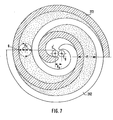
- Orbiting scroll 27 also includes a circular end plate 271 and a wrap or spiral element 272 affixed to or extending from one side surface of circular end plate 271. Spiral element 272 and spiral element 262 of fixed scroll 26 o interfit at an angular offset of 180 and a predetermined radial offset. At least a pair of fluid pockets are thereby defined between both spiral elements 262,272. Orbiting scroll 27, which is connected to the drive mechanism and to the rotation preventing/thrust bearing device,is driven in an orbital motion at a circular radius Ro by rotation of drive shaft 13 to thereby compress fluid passing through the compressor unit. Generally, radius Ro of orbital motion is given by the following formular
- the pitch (P) of the spiral elements can be defined by 2 rg, where rg is the involute generating circular radius.
- the radius of orbital motion Ro is also illustrated in Fig.7,as the locus of an arbitrary point Q on orbiting scroll 27.
- the spiral element 272 is radially offset from spiral element 262 of fixed scroll member 26 by the distance Ro.
- Orbiting scroll 27 undergoes orbital motion of a radius Ro upon rotation of drive shaft 13.
- the line contacts between spiral elements 262,272 move toward the center of the spiral elements along the surface of the spiral - elements.
- the fluid pockets which are defined by spiral elements 262,272, also move to the center with a consequent reduction in volume and compression of the fluid in the fluid pockets.
- the fluid or refrigerant gas which is introduced into suction chamber 29 from an external fluid circuit through inlet port 33, is drawn into the fluid pockets formed between spiral elements 262,272 from the outer ends of the spiral elements:
- the fluid then is discharged to the external fluid circuit through an outlet port 32.
- Drive shaft l3 which is rotatably supported by sleeve 15 through bearing 17, is connected to disk 18.
- Disk 18 is rotatably supported by front end plate 1 1 through bearing 19 disposed within opening 111 of front end plate 11.
- a crank pin or drive pin 33 axially projects from an axial end surface of disk 18 at a position which is radially offset from the center of drive shaft 13.
- Circular plate 271 of orbiting scroll 27 has a tubular boss 273 axially projecting from the end surface opposite the surface from which spiral element 272 extends.
- a discoid or short axial bushing 34 fits into boss 273 and is rotatably supported therein by a bearing, such as a needle bearing 35.
- Bushing 34 has a balance weight 341 which has the shaped of a semi-disk or ring radially connected to bushing 34 along a front surface thereof.
- An eccentric hole 342 is formed in bushing 34 at a position radially offset from the center of bushing 34.
- Drive pin 33 fits into eccentric hole 342 together with bearing 36.
- Bushing 34 which is driven by the revolution of drive pin 33, rotates within a bearing 35.
- orbiting scroll 27 is prevented by a rotation preventing/thrust bearing device 37 which is positioned between the inner wall of the housing 10 and circular plate 271 of orbting scroll 27 and around boss 273 of orbiting scroll 27.
- a rotation preventing/thrust bearing device 37 which is positioned between the inner wall of the housing 10 and circular plate 271 of orbting scroll 27 and around boss 273 of orbiting scroll 27.
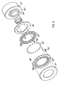
- Rotation preventing/thrust bearing device 37 includes a fixed portion, an orbital portion and bearings, such as a plurality of balls or spheres.
- Fixed portion includes (1) an annular race 37 1 and (2) fixed ring 372 formed separatly from fixed race 371.
- Annular fixed race 371 is placed within an annular groove formed on the axial end surface of annular projection 112 of front end plate 11.
- Fixed ring 372 is fitted against the axial end surface of annular projection 11 and fixed on its surface by pins 373, and has a width to cover the end surface of fixed race 371.
- the orbital portion also includes (1) an annular orbital race 374 and (2) an orbital ring 375 formed separatly from orbital race.
- Orbital race 374 is placed within an annular groove formed on the end surface of circular plate 272 of orbiting scroll 27.
- Orbital ring 375 is fitted against the end surface of circular plate 271 and fixed on the axial end surface of circular plate o 271 by pins 376, and has width to cover the end surface of orbital race 374.
- the fixed and orbital races 371 and 374 are fixed on the groove 274 and 113 by fitting or caulking.
- Fixed ring 372 and orbital ring 375 each have a plurality of holes or pockets 372a and 375a in the axial direction, the number of holes or pockets in each rings 372 and 375 being equal.
- Fixed ring 372 and orbital ring 375 face each other with a predetermined clearance.
- the radius of each pockets 372a of fixed ring 372 is formed greater than the radius of each pockets 375a of orbital ring 375.
- Pockets 372a of fixed ring 372 correspond to pockets 375a of orbital ring 375, i.e., at least each pair of pockets facing each other have the same pitch, and the radial distance of pockets from the center of their respective ring 372 and 375 is the same.
- each pair of pockets 372a and 375a are radially offset by the distance Ro.
- Bearings such as a plurality of balls, are placed between the edge of pockets 372a of fixed ring 372 and the edge of pockets 375a of orbital ring 375.
- each ball 377 is in contact with the axial end surface of orbital race 374, and rolls along the edge of pocket 375a.
- Ball 377 is also in contact with the axial end surface of fixed race 371, and rolls along the edge of pocket 372a of fixed ring 372.
- the locus of the contact point of each ball 377 on orbital race 374 is a circle which has a radius Rl, i.e., the traveling radius of each ball 377 with regard to the axial end surface of orbital race 374 is defined by the R1
- the locus of the contact point of each ball 377 on fixed race 371 is a circle which has a radius R2, i.e., the traveling radius of bé.1l 377 with regard to the axial end surface of fixed race 371 is defjied by the R2.
- the orbiting scroll 27 is thus permitted the orbital motion of the radius Ro. Since, if the total amount of traveling radius of each ball with regard to the fixed and orbital races 371 and 374 can be kept the orbital radius Ro, the radii of facing pockets 372a and 375a can be changed, and must not align each other.
- the maximum traveling radius of each ball 377 within pockets 375a of orbital ring 375 will be defined by , where Wor is the width of orbital ring 375 and Db is a diameter of ball 377, and the maximum traveling radius of each ball 377 within pockets 372a of fixed ring 372 will be also defined by , where Wfr is the width of fixed ring 372. Furthermore, the difference between the radii RI and R2 is selected to at least one tenth of the ball diameter or less for suitable operation.
- the tolerance limit of these amount of the radii is given by the following formula, where ⁇ 1 is a half of the tolerance of pocket diameter, ⁇ 2 is the maximum amount of error of center position of pocket, and ⁇ 3 is a half of tolerance of ball diameter. Because, the center of reaction force acted to circular plate 271 of orbiting scroll 27 and vector of the force are changed by the crank angle of drive shaft, and also the diameter of ball 377 has a dimensional error.
- the radii of orbital pockets 375a are formed smaller than the radii of fixed pockets 372a, the traveling radius of each ball with regard to the orbital race 374 can be made shorter.
- the width of the orbital race and ring 374 and 375 are thus made shorter, therefore the weight of the orbital portion of rotation preventing/thrust bearing device 37 which is attached to orbiting scroll 27 can be reduced. If the total weight of orbiting scroll assembly, which includes orbiting scroll 27, a part of the driving mechanism and the orbital portion of rotation preventing/thrust bearing device 37, is reduced, the weight of balance weight which holds the dynamic-balance of the orbital scroll assembly can be reduced and balance weight can be made simple construction.
Landscapes
- Engineering & Computer Science (AREA)
- General Engineering & Computer Science (AREA)
- Mechanical Engineering (AREA)
- Rotary Pumps (AREA)
Applications Claiming Priority (2)
| Application Number | Priority Date | Filing Date | Title |
|---|---|---|---|
| JP40405/81 | 1981-03-23 | ||
| JP56040405A JPS57157085A (en) | 1981-03-23 | 1981-03-23 | Apparatus having element moved along circular orbiting path |
Publications (2)
| Publication Number | Publication Date |
|---|---|
| EP0061698A1 true EP0061698A1 (de) | 1982-10-06 |
| EP0061698B1 EP0061698B1 (de) | 1986-01-29 |
Family
ID=12579745
Family Applications (1)
| Application Number | Title | Priority Date | Filing Date |
|---|---|---|---|
| EP82102401A Expired EP0061698B1 (de) | 1981-03-23 | 1982-03-23 | Vorrichtung mit kreisendem Kolben zum Fördern von Fluiden, mit einer Einrichtung zum Verhindern der Rotation |
Country Status (5)
| Country | Link |
|---|---|
| US (1) | US4474543A (de) |
| EP (1) | EP0061698B1 (de) |
| JP (1) | JPS57157085A (de) |
| AU (1) | AU549061B2 (de) |
| DE (1) | DE3268745D1 (de) |
Cited By (8)
| Publication number | Priority date | Publication date | Assignee | Title |
|---|---|---|---|---|
| GB2132276A (en) * | 1982-12-23 | 1984-07-04 | Copeland Corp | Scroll-type rotary fluid-machine |
| EP0122068A1 (de) * | 1983-03-15 | 1984-10-17 | Sanden Corporation | Einrichtung zum Einpassen der Spiralen für eine Verdrängermaschine der Spiralbauart |
| EP0123407A1 (de) * | 1983-03-15 | 1984-10-31 | Sanden Corporation | Einrichtung zum Verhindern der Rotation für eine Verdrängermaschine mit kreisendem Kolben |
| DE3441286A1 (de) * | 1983-11-14 | 1985-05-30 | Sanden Corp., Isesaki, Gunma | Spiralfluidverdraengervorrichtung |
| DE3441994A1 (de) * | 1983-11-19 | 1985-05-30 | Sanden Corp., Isesaki, Gunma | Rotationsverhinderungseinrichtung fuer das umlaufende element einer fluidverdraengervorrichtung |
| DE3510470A1 (de) * | 1984-03-21 | 1985-10-03 | Mitsubishi Jukogyo K.K., Tokio/Tokyo | Spiralkompressor |
| EP0122469B1 (de) * | 1983-03-15 | 1986-09-24 | Sanden Corporation | Schmiereinrichtung für Verdrängungsanlage mit ineinandergreifenden Spiralelementen |
| EP0192351B1 (de) * | 1985-01-28 | 1989-09-20 | Sanden Corporation | Flüssigkeitskompressor mit ineinandergreifenden Spiralelementen |
Families Citing this family (21)
| Publication number | Priority date | Publication date | Assignee | Title |
|---|---|---|---|---|
| US4609334A (en) * | 1982-12-23 | 1986-09-02 | Copeland Corporation | Scroll-type machine with rotation controlling means and specific wrap shape |
| US4877382A (en) * | 1986-08-22 | 1989-10-31 | Copeland Corporation | Scroll-type machine with axially compliant mounting |
| US4767293A (en) * | 1986-08-22 | 1988-08-30 | Copeland Corporation | Scroll-type machine with axially compliant mounting |
| JPH03105088A (ja) * | 1989-09-18 | 1991-05-01 | Sanden Corp | スクロール型圧縮機 |
| US5173042A (en) * | 1991-11-04 | 1992-12-22 | General Motors Corporation | Scroll compressor and discharge valve |
| JPH0630486U (ja) * | 1992-09-21 | 1994-04-22 | サンデン株式会社 | スクロール型圧縮機 |
| JP3053551B2 (ja) * | 1995-08-03 | 2000-06-19 | サンデン株式会社 | ボールカップリング |
| US5758978A (en) * | 1996-04-05 | 1998-06-02 | Ntn Corporation | Thrust ball bearing |
| JPH09303274A (ja) * | 1996-05-15 | 1997-11-25 | Sanden Corp | スクロール型圧縮機 |
| JP3136267B2 (ja) * | 1996-05-21 | 2001-02-19 | サンデン株式会社 | スクロール型圧縮機の回転阻止機構 |
| JP3115553B2 (ja) * | 1998-01-27 | 2000-12-11 | サンデン株式会社 | スクロール型流体機械における可動スクロールの自転阻止機構 |
| JP3299710B2 (ja) | 1998-02-05 | 2002-07-08 | サンデン株式会社 | スクロール型流体機械における可動スクロールの自転阻止機構 |
| JPH11241690A (ja) * | 1998-02-26 | 1999-09-07 | Sanden Corp | スクロール型流体機械 |
| JP2000055040A (ja) | 1998-08-04 | 2000-02-22 | Sanden Corp | ボールカップリング |
| JP3249781B2 (ja) * | 1998-08-05 | 2002-01-21 | サンデン株式会社 | スラスト玉軸受 |
| JP2001132664A (ja) | 1999-11-04 | 2001-05-18 | Sanden Corp | スクロール型圧縮機 |
| US6315460B1 (en) | 1999-12-29 | 2001-11-13 | Visteon Global Technologies, Inc. | Orbital motion bearing |
| KR20060015493A (ko) * | 2003-04-03 | 2006-02-17 | 고요 세이코 가부시키가이샤 | 편심 스러스트 베어링 |
| US20080157550A1 (en) * | 2006-12-30 | 2008-07-03 | Patrick Burgess | Multi-tool tweezer |
| US8057509B2 (en) | 2006-12-30 | 2011-11-15 | Goody Products, Inc. | Multi-tool tweezer |
| JP5150206B2 (ja) * | 2007-10-31 | 2013-02-20 | 株式会社日立産機システム | スクロール式流体機械 |
Citations (4)
| Publication number | Priority date | Publication date | Assignee | Title |
|---|---|---|---|---|
| US1906142A (en) * | 1930-04-02 | 1933-04-25 | Ekelof John | Rotary pump or compressor |
| DE2831179A1 (de) * | 1978-07-15 | 1980-01-24 | Leybold Heraeus Gmbh & Co Kg | Verdraengermaschine nach dem spiralprinzip |
| US4259043A (en) * | 1977-06-17 | 1981-03-31 | Arthur D. Little, Inc. | Thrust bearing/coupling component for orbiting scroll-type machinery and scroll-type machinery incorporating the same |
| US4303379A (en) * | 1978-09-09 | 1981-12-01 | Sankyo Electric Company Limited | Scroll-type compressor with reduced housing radius |
Family Cites Families (3)
| Publication number | Priority date | Publication date | Assignee | Title |
|---|---|---|---|---|
| FR976187A (de) * | 1951-03-14 | |||
| FR928465A (fr) * | 1946-05-28 | 1947-11-28 | Machine rotative fonctionnant comme pompe, compresseur, etc. | |
| US4160629A (en) * | 1977-06-17 | 1979-07-10 | Arthur D. Little, Inc. | Liquid immersible scroll pump |
-
1981
- 1981-03-23 JP JP56040405A patent/JPS57157085A/ja active Granted
-
1982
- 1982-03-22 AU AU81789/82A patent/AU549061B2/en not_active Expired
- 1982-03-23 US US06/361,108 patent/US4474543A/en not_active Expired - Lifetime
- 1982-03-23 EP EP82102401A patent/EP0061698B1/de not_active Expired
- 1982-03-23 DE DE8282102401T patent/DE3268745D1/de not_active Expired
Patent Citations (4)
| Publication number | Priority date | Publication date | Assignee | Title |
|---|---|---|---|---|
| US1906142A (en) * | 1930-04-02 | 1933-04-25 | Ekelof John | Rotary pump or compressor |
| US4259043A (en) * | 1977-06-17 | 1981-03-31 | Arthur D. Little, Inc. | Thrust bearing/coupling component for orbiting scroll-type machinery and scroll-type machinery incorporating the same |
| DE2831179A1 (de) * | 1978-07-15 | 1980-01-24 | Leybold Heraeus Gmbh & Co Kg | Verdraengermaschine nach dem spiralprinzip |
| US4303379A (en) * | 1978-09-09 | 1981-12-01 | Sankyo Electric Company Limited | Scroll-type compressor with reduced housing radius |
Cited By (9)
| Publication number | Priority date | Publication date | Assignee | Title |
|---|---|---|---|---|
| GB2132276A (en) * | 1982-12-23 | 1984-07-04 | Copeland Corp | Scroll-type rotary fluid-machine |
| EP0122068A1 (de) * | 1983-03-15 | 1984-10-17 | Sanden Corporation | Einrichtung zum Einpassen der Spiralen für eine Verdrängermaschine der Spiralbauart |
| EP0123407A1 (de) * | 1983-03-15 | 1984-10-31 | Sanden Corporation | Einrichtung zum Verhindern der Rotation für eine Verdrängermaschine mit kreisendem Kolben |
| EP0122469B1 (de) * | 1983-03-15 | 1986-09-24 | Sanden Corporation | Schmiereinrichtung für Verdrängungsanlage mit ineinandergreifenden Spiralelementen |
| AU601615B2 (en) * | 1983-03-15 | 1990-09-13 | Sanden Corporation | Rotation-preventing device for an orbiting piston-type fluid displacement apparatus |
| DE3441286A1 (de) * | 1983-11-14 | 1985-05-30 | Sanden Corp., Isesaki, Gunma | Spiralfluidverdraengervorrichtung |
| DE3441994A1 (de) * | 1983-11-19 | 1985-05-30 | Sanden Corp., Isesaki, Gunma | Rotationsverhinderungseinrichtung fuer das umlaufende element einer fluidverdraengervorrichtung |
| DE3510470A1 (de) * | 1984-03-21 | 1985-10-03 | Mitsubishi Jukogyo K.K., Tokio/Tokyo | Spiralkompressor |
| EP0192351B1 (de) * | 1985-01-28 | 1989-09-20 | Sanden Corporation | Flüssigkeitskompressor mit ineinandergreifenden Spiralelementen |
Also Published As
| Publication number | Publication date |
|---|---|
| AU549061B2 (en) | 1986-01-09 |
| EP0061698B1 (de) | 1986-01-29 |
| AU8178982A (en) | 1982-09-30 |
| JPS6151676B2 (de) | 1986-11-10 |
| US4474543A (en) | 1984-10-02 |
| JPS57157085A (en) | 1982-09-28 |
| DE3268745D1 (en) | 1986-03-13 |
Similar Documents
| Publication | Publication Date | Title |
|---|---|---|
| EP0061698A1 (de) | Vorrichtung mit kreisendem Kolben zum Fördern von Fluiden, mit einer Einrichtung zum Verhindern der Rotation | |
| EP0078148B1 (de) | Vorgespannte Antriebseinrichtung für kreisendes, fluidverdrängendes Maschinenteil | |
| EP0060495B1 (de) | Rotationsverhinderungseinrichtung für eine Kreiskolben-Fluidumanlage | |
| EP0038152B1 (de) | Fluidumverdrängermaschinen mit ineinander greifenden Spiralelementen | |
| EP0091544A2 (de) | Synchronisiervorrichtung für eine spiralförmige Fluidumverdrängermaschine | |
| US4589828A (en) | Rotation preventing device for an orbiting member of a fluid displacement apparatus | |
| EP0037728B1 (de) | Fluidumverdichter mit Exzenterspiralelementen | |
| US4645435A (en) | Rotation preventing device for an orbiting member of a fluid displacement apparatus | |
| EP0061064B1 (de) | Kreiskolben-Fluidumverdrängungsanlage mit Mitteln zur Rotationsverhinderung | |
| EP0052461A1 (de) | Fluidumverdrängeranlage mit Exzenterschneckenelementen und Mitteln zum Entgegenwirken von Fliehkräften | |
| EP0419204B1 (de) | Vorrichtung mit kreisendem Kolben zum Fördern von Fluiden mit einer Einrichtung zum Verhindern der Rotation | |
| EP0123407B1 (de) | Einrichtung zum Verhindern der Rotation für eine Verdrängermaschine mit kreisendem Kolben | |
| EP0078128B1 (de) | Stützenlager für Fluidumverdrängungsmaschine | |
| US4411604A (en) | Scroll-type fluid displacement apparatus with cup shaped casing | |
| US5738504A (en) | Rotation preventing device for orbiting member of fluid displacement apparatus | |
| US5435706A (en) | Orbiting member fluid displacement apparatus with rotation preventing mechanism | |
| EP0065261A2 (de) | Axialdichtung für eine Spiralverdrängermaschine | |
| US4435136A (en) | Orbiting piston type fluid displacement apparatus with shaft bearing and seal mechanisms | |
| EP0075053A1 (de) | Verschleissfeste Mittel für eine Fluidumverdrängungsanlage mit Exzenterspiralelementen | |
| CA2279478A1 (en) | Rotation preventing device for orbiting member of fluid displacement apparatus |
Legal Events
| Date | Code | Title | Description |
|---|---|---|---|
| PUAI | Public reference made under article 153(3) epc to a published international application that has entered the european phase |
Free format text: ORIGINAL CODE: 0009012 |
|
| AK | Designated contracting states |
Designated state(s): DE FR GB IT SE |
|
| 17P | Request for examination filed |
Effective date: 19830304 |
|
| RAP1 | Party data changed (applicant data changed or rights of an application transferred) |
Owner name: SANDEN CORPORATION |
|
| ITF | It: translation for a ep patent filed | ||
| GRAA | (expected) grant |
Free format text: ORIGINAL CODE: 0009210 |
|
| AK | Designated contracting states |
Designated state(s): DE FR GB IT SE |
|
| ET | Fr: translation filed | ||
| REF | Corresponds to: |
Ref document number: 3268745 Country of ref document: DE Date of ref document: 19860313 |
|
| PLBE | No opposition filed within time limit |
Free format text: ORIGINAL CODE: 0009261 |
|
| STAA | Information on the status of an ep patent application or granted ep patent |
Free format text: STATUS: NO OPPOSITION FILED WITHIN TIME LIMIT |
|
| 26N | No opposition filed | ||
| ITTA | It: last paid annual fee | ||
| EAL | Se: european patent in force in sweden |
Ref document number: 82102401.5 |
|
| PGFP | Annual fee paid to national office [announced via postgrant information from national office to epo] |
Ref country code: SE Payment date: 20010306 Year of fee payment: 20 |
|
| PGFP | Annual fee paid to national office [announced via postgrant information from national office to epo] |
Ref country code: FR Payment date: 20010313 Year of fee payment: 20 |
|
| PGFP | Annual fee paid to national office [announced via postgrant information from national office to epo] |
Ref country code: DE Payment date: 20010319 Year of fee payment: 20 |
|
| PGFP | Annual fee paid to national office [announced via postgrant information from national office to epo] |
Ref country code: GB Payment date: 20010321 Year of fee payment: 20 |
|
| REG | Reference to a national code |
Ref country code: GB Ref legal event code: IF02 |
|
| PG25 | Lapsed in a contracting state [announced via postgrant information from national office to epo] |
Ref country code: GB Free format text: LAPSE BECAUSE OF EXPIRATION OF PROTECTION Effective date: 20020322 |
|
| REG | Reference to a national code |
Ref country code: GB Ref legal event code: PE20 Effective date: 20020322 |
|
| EUG | Se: european patent has lapsed |
Ref document number: 82102401.5 |