EP0065261A2 - Axialdichtung für eine Spiralverdrängermaschine - Google Patents
Axialdichtung für eine Spiralverdrängermaschine Download PDFInfo
- Publication number
- EP0065261A2 EP0065261A2 EP82104075A EP82104075A EP0065261A2 EP 0065261 A2 EP0065261 A2 EP 0065261A2 EP 82104075 A EP82104075 A EP 82104075A EP 82104075 A EP82104075 A EP 82104075A EP 0065261 A2 EP0065261 A2 EP 0065261A2
- Authority
- EP
- European Patent Office
- Prior art keywords
- groove
- seal element
- fluid
- spiral
- scroll member
- Prior art date
- Legal status (The legal status is an assumption and is not a legal conclusion. Google has not performed a legal analysis and makes no representation as to the accuracy of the status listed.)
- Granted
Links
Images


Classifications
-
- F—MECHANICAL ENGINEERING; LIGHTING; HEATING; WEAPONS; BLASTING
- F01—MACHINES OR ENGINES IN GENERAL; ENGINE PLANTS IN GENERAL; STEAM ENGINES
- F01C—ROTARY-PISTON OR OSCILLATING-PISTON MACHINES OR ENGINES
- F01C19/00—Sealing arrangements in rotary-piston machines or engines
- F01C19/08—Axially-movable sealings for working fluids
-
- F—MECHANICAL ENGINEERING; LIGHTING; HEATING; WEAPONS; BLASTING
- F01—MACHINES OR ENGINES IN GENERAL; ENGINE PLANTS IN GENERAL; STEAM ENGINES
- F01C—ROTARY-PISTON OR OSCILLATING-PISTON MACHINES OR ENGINES
- F01C1/00—Rotary-piston machines or engines
- F01C1/02—Rotary-piston machines or engines of arcuate-engagement type, i.e. with circular translatory movement of co-operating members, each member having the same number of teeth or tooth-equivalents
- F01C1/0207—Rotary-piston machines or engines of arcuate-engagement type, i.e. with circular translatory movement of co-operating members, each member having the same number of teeth or tooth-equivalents both members having co-operating elements in spiral form
- F01C1/0215—Rotary-piston machines or engines of arcuate-engagement type, i.e. with circular translatory movement of co-operating members, each member having the same number of teeth or tooth-equivalents both members having co-operating elements in spiral form where only one member is moving
Definitions
- This invention relates to a fluid displacement apparatus, and more particularly, to an axial sealing mechanism for a scroll type fluid displacement apparatus.
- Scroll type fluid displacement apparatus are well known in the prior art.
- U.S.Patent No. 801,182 discloses a device including two scroll members each having a circular end plate and a spiroidal or involute spiral element. These scroll members are maintained angularly and radially offset so that both spiral elements interfit to make a plurality of line contacts between their spiral curved surfaces to thereby seal off and define at least one pair of fluid pockets.
- the relative orbital motion of the two scroll members shifts the line contacts along the spiral curved surfaces and, therefore, the fluid pockets change in volume. Since the volume of the fluid pockets increases or decreases dependent on the direction of the orbiting motion, the scroll type fluid displacement apparatus is applicable to compress, expand or pump fluids.
- the scroll type compressor In comparison with conventional compressors of the piston type, the scroll type compressor has certain advantages, such as reduced parts and continuous compression of fluid.
- one of the problems encountered in prior art scroll type compressors has been ineffective sealing of the fluid pockets. Axial and radial sealing of the fluid pockets must be maintained in a scroll type compressor in order to achieve efficient operation.
- the fluid pockets in a scroll type compressor are defined by both line contacts between the interfitting spiral elements and axial contacts between the axial end surfaces of the spiral elements and the inner end surface of the end plates.
- U.S.P atent No. 3,874,827 discloses a non-rotatable fixed scroll member supported within the housing of scroll apparatus in an axially floating condition.
- a high pressure fluid is introduced behind the fixed scroll member to establish sufficient axial sealing.
- Young patent is supported in the axial floating condition, the fixed scroll member may wobble due to the eccentric orbital motion of the orbiting scroll member. Therefore, axial and radial sealing of the fluid pockets and resultant fluid compression, tend to be imperfectly performed.
- the pressure of the high pressure fluid must be increased and the clearance between radial supporting parts must be made as small as possible.
- minimizing the clearance is expensive due to the close tolerance requirements, while an increase in pressure increases contact pressure between both scroll members, which increases mechanical loss or causes damage to the scroll members.
- Another technique for improving the axial seal of the fluid pockets is to be use sealing element mounted in the axial end surface of each spiral elements, as described in U.S.Patent No. 3,994;635.
- the end surface of each spiral element facing the end plate of the other scroll member is provided with a groove formed along the spiral.
- a seal element is placed within the groove and an axial force urging device, such as a spring, is placed behind the seal element to urge the seal element toward the facing end surface of the end plate to thereby effect axial sealing.
- the construction of the axial force urging device is complex and it is difficult to obtain the desired uniform sealing force along the entire length of the seal element.
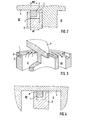
- Figs. 1-5 illustrate a more simple construction of the axial sealing mechanism to avoid these disadvantages.
- Fig.l shows a diagrammatic sectional view illustrating the spiral element of the fixed and orbiting scroll members and Fig. 2 shows sectional view taken along a line II-II in Fig. 1.
- a seal element.1 is loosely fitted into a groove 2 formed in the axial end surface of each spiral element 3, i.e., the width W2 of seal element 1 is formed smaller than the width W 1 of groove 2 and also the depth D 2 of seal element 1 is formed smaller than the depth D 1 of groove 2, as shown in'Fig. 2.
- the pressurized fluid then is introduced into groove 2 from adjacent pockets through the gap C, which is defined between the side surface of seal element 1 and the inner end surface of groove 2, and seal element 1 is urged toward the axial and radial direction to contact with the facing end plate 4 and the one side surface of groove 2.
- the urging force towards radial direction is shown by arrow in Fig. 1.
- the fluid within a high pressure chamber A whichis defined by the center portions of the spiral elements, leaks into the adjacent lower pressure chambers B 1 and B 2 , and also fluid within lower pressure chambers B and B 2 leaks into the suction chamber defined by the outer peripheral portion of the scroll members. Since groove 2 in which seal element 1 is disposed extends from the center of spiral element to near the terminal end thereof. Furthermore, as shown in Fig. 4 which is a sectional view taken along a line IV-IV in Fig. 1, the fluid within the high pressure chamber A or lower pressure chambers B 1 and B 2 leaks into the adjacent lower chambers B 1 and B 2 or the suction chamber through the contact surface between the axial end surface of seal element 1 and the inner end surface of facing end plate 4. Therefore, the volume efficiency of the compressor is reduced.
- both scroll members are expanded each other by the pressure within the fluid pockets and the orbiting scroll member is pushed against an axial thrust bearing device.
- the driving point of the orbiting scroll member which point is placed on the side surface of the end plate opposite the spiral element extending, is offset from the acting point of the reaction force caused by the compression of gas, which point is - placed on the intermediate along the height of spiral element of the orbiting scroll member. Therefore, the resultant moment causes the axial slant of the orbiting scroll member. Also, in a transit condition of such as a moment to turn on or off the magnetic clutch or sudden change of the operating condition, the orbiting scroll member is not uniformly pushed against the axial thrust bearing which is placed between the end plate of the orbiting scroll member and the fixed plate portion. Therefore, the axial slant of the orbiting scroll member is caused.
- the seal element is disposed within the groove in an axially and radially floating condition, and pushed against toward facing end plate by pressurized fluid.
- Fig. 1 and Fig. 5 which is a sectional view taken along a line V-V in Fig. 1, a part of seal element 1 extends the no pressure differential area. The area is shown by a part of D in Fig. 1..
- the seal element 1 cannot receive the urging force toward the axial and radial direction, and seal element 1 can therefore freely move within the groove 2 and comes into contact with the inner end surface of facing end plate 4, as shown in Fig. 5, to thereby arise the abnormal wear.
- a scroll type fluid displacement apparatus includes a pair of scroll members each comprising a circular end plate and a spiral wrap extending from one side of the circular end plate.
- a groove is formed in the axial end surface of each spiral wrap and extends along the spiral curve of the wrap.
- a seal element is fitted in the groove.
- the axial dimension of the seal element is greater than the depth of the groove.
- the axial end surface of seal element is, therefore, usually contact with the inner end surface of the facing end plate without any axial force urging device, after assembling the compressor. Accordingly, the gap between the seal element and the groove which defines the channel of leakage fluid is reduced.
- a fluid displacement apparatus in accordance with the present invention is shown which is a scroll type refrigerant compressor.
- the compressor includes a compressor housing 10 having a front end plate 11 and a cup shaped casing 12 fastened to an end surface of front end plate 11.
- An opening 111 is formed in the center of front end plate 11 for supporting a drive shaft 13.
- An annular projection 112, concentric with opening 111, is formed on the rear end surface of front end plate 11 facing cup shaped casing 12.
- An outer peripheral surface of annular projection 112 fits into an inner wall of the opening of cup shaped casing 12.
- Cup shaped casing 12 is fixed on the rear end surface of front end plate 11 by a fastening device, such as bolts and nuts, so that the opening of cup shaped casing 12 is covered by front end plate 11.
- An 0-ring 14 is placed between the outer peripheral surface of annular projection 112 and the inner wall of cup shaped casing 12.
- Front end plate 11 has an annular sleeve 15 projecting from the front end surface thereof; this sleeve 15 surrounds drive shaft 13 to define a shaft seal cavity.
- sleeve 15 is attached to the front end surface of front end plate 11 by screws 16, one of which is shown in Fig. 6.
- An 0-ring 17 is placed between the front end surface of front end plate 11 and an end surface of sleeve 15 to seal the mating surface of front end plate 11 and sleeve 15.
- sleeve 15 may be formed integral with front end plate 11.
- Drive shaft 13 is rotatably supported by sleeve 15 through a bearing 18 disposed within the front end of sleeve 15.
- Drive shaft 13 has a disk shaped rotor 19 at its inner end; disk shaped rotor 19 is rotatably supported by front end plate 11 through a bearing 20 disposed within opening 111 of front end plate 11.
- a shaft seal assembly 21 is assembled on drive shaft 13 within the shaft seal cavity of sleeve 15.
- a pulley 22 is rotatably supported by a bearing 23 on the outer surface of sleeve 15.
- An electromagnetic coil 24, which is received in an annular cavity of pulley 22, is mounted on the outer surface of sleeve 15 by a supported plate 241.
- An armature plate 25 is elastically supported on the outer end of drive shaft 13 which extends from sleeve 15.
- a magnetic clutch is formed by pulley 22, magnetic coil 24 and armature plate 25.
- a number of elements are located within the inner chamber of cup shaped casing 12 including a fixed scroll 26 ,an orbiting scroll 27, a driving mechanism for orbiting scroll 27 and a rotation preventing/thrust bearing device 28 for orbiting scroll 27.
- the inner chamber of cup shaped casing 12 is formed between the inner wall of cup shaped casing 12 and front end plate 11.
- Fixed scroll 26 includes a circular end plate 261, a wrap or spiral. element 262 affixed to or extending from one end surface of circular end plate 261, and a plurality of internal bosses 263 axially projecting from the end surface of circular end plate 261 on the side opposite spiral element 262 extending.
- the end surface of each boss 263 is seated on the inner surface of end plate portion 121 of cup shaped casing 12 and is fixed to end plate portion 121 by a plurality of bolts 29, one of which is shown in Fig. 6.
- fixed scroll 26 is fixedly disposed within cup shaped casing 12.
- Circular end plate 261 of fixed scroll 26 partitions the inner chamber of cup shaped casing 12 into a rear chamber 30 having bosses 263, and a front chamber 31, ' in which spiral element 262 of fixed scroll 26 is located.
- a sealing member 32 is disposed within circumferential groove 264 of circular end plate 261 for sealing the outer peripheral surface of circular end plate 261 and the inner wall of cup shaped casing 12.
- a hole or disharge port 265 is formed-through circular end plate 261 at a position near the center of spiral element 262; discharge port 265 connects the fluid pockets at the center of spiral element 262 and rear chamber 30.
- Orbiting scroll 27 which is disposed in front chamber 31, includes a circular end plate 271 and a wrap or spiral element 272 affixed to or extending from one end surface of circular end plate 271.
- the spiral elements 262 and 272 interfit at an angular offset of 180 0 and a predetermined radial offset.
- the spiral elements define at least a pair of fluid pockets between their interfitting surfaces.
- Orbiting scroll 27 is connected to the driving mechanism and the rotation preventing/thrust bearing device 28.
- the driving mechanism and the rotation preventing/ thrust bearing device 28 effect orbital motion of orbiting scroll 27 by the rotation of drive shaft 13 to thereby compress fluid passing through the compressor.
- drive shaft 13 which is rotatably supported by sleeve 15 through bearing 18, has disk shaped rotor 19 at its inner end.
- Disk shaped rotor 19 is also rotatably supported by front end plate 11 through bearing 20.
- a crank pin or drive pin 191 projects axially from an axial end surface of disk shaped rotor 19 and is radially offset from the center of drive shaft 13.
- Circular end plate 271 of orbiting scroll 27 is provided with a tubular boss 273 axially projecting from the surface opposite to the end surface from which spiral element 272 extends.
- a discoid or short axial bushing 33 fits into boss 273, and is rotatably supported therein by a bearing, such as needle bearing 34.
- An eccentric hole is formed on bushing 33; the eccentric hole is radially offset from the center of bushing 33.
- Drive pin191 which is surrounded by bearing 39, fits into the eccentric hole. Therefore, bushing 33 is driven by the revolution of drive pin 191to thereby 27 rotate within bearing 34.
- the spiral element of orbiting scroll/ is thus pushed against the spiral element of fixed scroll 26 due to the moment created by the differential of the driving point and the reaction point of pressure gas for secured the line contacts.
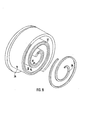
- Rotation preventing/thrust bearing device 28 is placed between the inner end surface of front end plate 11 and the end surface of circular end plate 271 which faces the inner end surface of front end plate 11, as shown in Fig. 6, and includes a fixed ring 281, which is fastened against the axial end surface of annular projection 112, an orbiting ring 282, which is fastened against the end surface of circular end plate 272 by a fastening device, and a bearing element, such as a plurality of spherical balls' 283. Rings 281 and 282 have a plurality of indentations 284 and 285 and one of spherical ball 283 is retained between each of these indentations 284 and 285.
- each spiral element 262 and 272 is provided with a groove 37 formed in its axial end surface along the spiral curve' of the spiral element.
- Groove 37 extends from the inner end portion of the spiral element to a position close to the terminal end of the spiral element.
- a seal element 38 is fitted within each groove 37.
- at least the axial dimension D 2 of seal element 38 is formed greater than the depth D 1 of groove 37. Seal element 38 thus usually contacts with the inner end surface of facing circular end plate without any axial force urging device. Therefore, axial sealing of the fluid pockets will be secured.
- the gap C defined by the end plate 261, side wall of the spiral element 262, the axial end surface of facing spiral element 272 and seal element 38 fitted in the groove 37 of facing spiral element 272 will be reduced, and the amount of the fluid leakage from the high pressure chamber to lower pressure chamber is reduced. Therefore, the volume efficiency of the compressor is improved.
- the width of the groove will be made as large as possible and the width of the seal element is made larger dependent on the width of the groove. Therefore, the width of contact surface between the seal element and the inner end surface of facing end plate will be made larger, so that the fluid leakage through the contact surface will be reduced.
- the width W 2 of seal element 38 is formed smaller than the width W 1 of groove 37. Therefore, the problem in that the assembling of the seal element into the groove would be in difficulty which is caused by the limit of the tolerance to surface roughness or width of the groove to be worked, or the width of seal element, is resolved. Also, if seal and/ element is formed of hard plastic / or self-lubricating material, the deformation of the seal element would occur in the long operation of the compressor. That is, the axial dimension of the seal element is reduced by the axial slant of the scroll, while the width of the seal element is increased. The increase of the width can be permitted by the differential of the width, and thereby secures the long life sealing of the fluid pockets.
- Fig. 10 shows an alternative embodiment of the present invention which is characterized in that the width W 2 of seal element 38 is formed substantially same as the width W 1 of groove 37.
- the construction will more reduce the gap C, and therefore, the amount of fluid leakage is reduced and volume efficiency of the compressor is improved.
Landscapes
- Engineering & Computer Science (AREA)
- Mechanical Engineering (AREA)
- General Engineering & Computer Science (AREA)
- Rotary Pumps (AREA)
Applications Claiming Priority (4)
| Application Number | Priority Date | Filing Date | Title |
|---|---|---|---|
| JP68235/81 | 1981-05-11 | ||
| JP6823581U JPS57180182U (de) | 1981-05-11 | 1981-05-11 | |
| JP10328281U JPS588783U (ja) | 1981-07-11 | 1981-07-11 | スクロ−ル型圧縮機 |
| JP103282/81 | 1981-07-11 |
Publications (3)
| Publication Number | Publication Date |
|---|---|
| EP0065261A2 true EP0065261A2 (de) | 1982-11-24 |
| EP0065261A3 EP0065261A3 (en) | 1983-02-16 |
| EP0065261B1 EP0065261B1 (de) | 1985-08-14 |
Family
ID=26409457
Family Applications (1)
| Application Number | Title | Priority Date | Filing Date |
|---|---|---|---|
| EP19820104075 Expired EP0065261B1 (de) | 1981-05-11 | 1982-05-11 | Axialdichtung für eine Spiralverdrängermaschine |
Country Status (4)
| Country | Link |
|---|---|
| EP (1) | EP0065261B1 (de) |
| AU (1) | AU551894B2 (de) |
| DE (1) | DE3265388D1 (de) |
| SG (1) | SG26487G (de) |
Cited By (12)
| Publication number | Priority date | Publication date | Assignee | Title |
|---|---|---|---|---|
| DE3317696A1 (de) * | 1983-05-16 | 1984-11-22 | Volkswagenwerk Ag, 3180 Wolfsburg | Verdraengermaschine fuer kompressible medien |
| EP0165714A2 (de) * | 1984-05-18 | 1985-12-27 | Mitsubishi Denki Kabushiki Kaisha | Anlage mit ineinandergreifenden Exzenterspiralelementen und ihr Montageverfahren |
| US4561832A (en) * | 1983-03-14 | 1985-12-31 | Sanden Corporation | Lubricating mechanism for a scroll-type fluid displacement apparatus |
| EP0189650A2 (de) * | 1985-01-28 | 1986-08-06 | Sanden Corporation | Axialdichtungseinrichtung für Spiralkompressor |
| DE3614614A1 (de) * | 1985-05-16 | 1986-11-20 | Mitsubishi Denki K.K., Tokio/Tokyo | Stoemungsmaschine der spiralbauart |
| US4627799A (en) * | 1984-08-27 | 1986-12-09 | Sanden Corporation | Axial sealing mechanism for a scroll type fluid displacement apparatus |
| EP0227249A1 (de) * | 1985-10-25 | 1987-07-01 | Sanden Corporation | Axialdichtungsmechanismus für ein Fluidverdrängungsgerät der Spiralbauweise |
| US4795324A (en) * | 1985-11-27 | 1989-01-03 | Mitsubishi Denki Kabushiki Kaisha | Scroll-type fluid transferring machine with deformable thrust bearing |
| US5642970A (en) * | 1995-04-26 | 1997-07-01 | Nippondenso Co., Ltd. | Method of producing a curved groove in a workpiece |
| US5702241A (en) * | 1995-04-19 | 1997-12-30 | Sanden Corporation | Scroll-type fluid displacement apparatus having sealing means for central portions of the wraps |
| EP0840012A1 (de) * | 1996-10-30 | 1998-05-06 | Carrier Corporation | Spiralverdichter |
| CN1056215C (zh) * | 1995-10-26 | 2000-09-06 | 倪诗茂 | 容积式涡旋流体压缩装置的分段式前端密封装置 |
Families Citing this family (1)
| Publication number | Priority date | Publication date | Assignee | Title |
|---|---|---|---|---|
| JP3281752B2 (ja) * | 1995-03-30 | 2002-05-13 | 三菱重工業株式会社 | スクロール型流体機械 |
Citations (4)
| Publication number | Priority date | Publication date | Assignee | Title |
|---|---|---|---|---|
| US3994635A (en) * | 1975-04-21 | 1976-11-30 | Arthur D. Little, Inc. | Scroll member and scroll-type apparatus incorporating the same |
| US3994636A (en) * | 1975-03-24 | 1976-11-30 | Arthur D. Little, Inc. | Axial compliance means with radial sealing for scroll-type apparatus |
| US3994633A (en) * | 1975-03-24 | 1976-11-30 | Arthur D. Little, Inc. | Scroll apparatus with pressurizable fluid chamber for axial scroll bias |
| DE2754288A1 (de) * | 1976-12-06 | 1978-06-08 | Tat Aero Equipment Ind Ltd | Verfahren zur radialen abdichtung eines zwischen einem stator und einem rotor befindlichen fluidvolumens und vorrichtung zur durchfuehrung des verfahrens |
-
1982
- 1982-05-10 AU AU83562/82A patent/AU551894B2/en not_active Expired
- 1982-05-11 EP EP19820104075 patent/EP0065261B1/de not_active Expired
- 1982-05-11 DE DE8282104075T patent/DE3265388D1/de not_active Expired
-
1987
- 1987-03-13 SG SG26487A patent/SG26487G/en unknown
Patent Citations (4)
| Publication number | Priority date | Publication date | Assignee | Title |
|---|---|---|---|---|
| US3994636A (en) * | 1975-03-24 | 1976-11-30 | Arthur D. Little, Inc. | Axial compliance means with radial sealing for scroll-type apparatus |
| US3994633A (en) * | 1975-03-24 | 1976-11-30 | Arthur D. Little, Inc. | Scroll apparatus with pressurizable fluid chamber for axial scroll bias |
| US3994635A (en) * | 1975-04-21 | 1976-11-30 | Arthur D. Little, Inc. | Scroll member and scroll-type apparatus incorporating the same |
| DE2754288A1 (de) * | 1976-12-06 | 1978-06-08 | Tat Aero Equipment Ind Ltd | Verfahren zur radialen abdichtung eines zwischen einem stator und einem rotor befindlichen fluidvolumens und vorrichtung zur durchfuehrung des verfahrens |
Cited By (24)
| Publication number | Priority date | Publication date | Assignee | Title |
|---|---|---|---|---|
| US4561832A (en) * | 1983-03-14 | 1985-12-31 | Sanden Corporation | Lubricating mechanism for a scroll-type fluid displacement apparatus |
| EP0118900B1 (de) * | 1983-03-14 | 1986-09-10 | Sanden Corporation | Schmierungseinrichtung für Verdrängermaschine mit ineinandergreifenden Spiralelementen |
| DE3317696A1 (de) * | 1983-05-16 | 1984-11-22 | Volkswagenwerk Ag, 3180 Wolfsburg | Verdraengermaschine fuer kompressible medien |
| EP0165714A3 (en) * | 1984-05-18 | 1987-05-27 | Mitsubishi Denki Kabushiki Kaisha | Scroll-type apparatus and method for the assembly thereof |
| EP0165714A2 (de) * | 1984-05-18 | 1985-12-27 | Mitsubishi Denki Kabushiki Kaisha | Anlage mit ineinandergreifenden Exzenterspiralelementen und ihr Montageverfahren |
| US4730375A (en) * | 1984-05-18 | 1988-03-15 | Mitsubishi Denki Kabushiki Kaisha | Method for the assembly of a scroll-type apparatus |
| US4655697A (en) * | 1984-05-18 | 1987-04-07 | Mitsubishi Denki Kabushiki Kaisha | Scroll-type apparatus with gap adjustment means |
| US4627799A (en) * | 1984-08-27 | 1986-12-09 | Sanden Corporation | Axial sealing mechanism for a scroll type fluid displacement apparatus |
| EP0189650A2 (de) * | 1985-01-28 | 1986-08-06 | Sanden Corporation | Axialdichtungseinrichtung für Spiralkompressor |
| US4701115A (en) * | 1985-01-28 | 1987-10-20 | Sanden Corporation | Axial sealing mechanism for a scroll compressor |
| EP0189650A3 (en) * | 1985-01-28 | 1987-11-11 | Sanden Corporation | Axial sealing mechanism for a scroll compressor |
| US4824343A (en) * | 1985-05-16 | 1989-04-25 | Mitsubishi Denki Kabushiki Kaisha | Scroll-type fluid transferring machine with gap adjustment between scroll members |
| DE3614614A1 (de) * | 1985-05-16 | 1986-11-20 | Mitsubishi Denki K.K., Tokio/Tokyo | Stoemungsmaschine der spiralbauart |
| US4740143A (en) * | 1985-05-16 | 1988-04-26 | Mitsubishi Denki Kabushiki Kaisha | Scroll-type fluid transferring machine with gap adjustment between scroll members |
| US4722676A (en) * | 1985-10-25 | 1988-02-02 | Sanden Corporation | Axial sealing mechanism for scroll type fluid displacement apparatus |
| EP0227249A1 (de) * | 1985-10-25 | 1987-07-01 | Sanden Corporation | Axialdichtungsmechanismus für ein Fluidverdrängungsgerät der Spiralbauweise |
| AU587647B2 (en) * | 1985-10-25 | 1989-08-24 | Sanden Corporation | Axial sealing mechanism for scroll type fluid displacement apparatus |
| US4795324A (en) * | 1985-11-27 | 1989-01-03 | Mitsubishi Denki Kabushiki Kaisha | Scroll-type fluid transferring machine with deformable thrust bearing |
| US5702241A (en) * | 1995-04-19 | 1997-12-30 | Sanden Corporation | Scroll-type fluid displacement apparatus having sealing means for central portions of the wraps |
| US5642970A (en) * | 1995-04-26 | 1997-07-01 | Nippondenso Co., Ltd. | Method of producing a curved groove in a workpiece |
| CN1056215C (zh) * | 1995-10-26 | 2000-09-06 | 倪诗茂 | 容积式涡旋流体压缩装置的分段式前端密封装置 |
| EP0840012A1 (de) * | 1996-10-30 | 1998-05-06 | Carrier Corporation | Spiralverdichter |
| US5833443A (en) * | 1996-10-30 | 1998-11-10 | Carrier Corporation | Scroll compressor with reduced separating force between fixed and orbiting scroll members |
| US5873711A (en) * | 1996-10-30 | 1999-02-23 | Carrier Corporation | Scroll compressor with reduced separating force between fixed and orbiting scroll members |
Also Published As
| Publication number | Publication date |
|---|---|
| DE3265388D1 (en) | 1985-09-19 |
| EP0065261A3 (en) | 1983-02-16 |
| EP0065261B1 (de) | 1985-08-14 |
| AU551894B2 (en) | 1986-05-15 |
| SG26487G (en) | 1987-07-10 |
| AU8356282A (en) | 1982-11-18 |
Similar Documents
| Publication | Publication Date | Title |
|---|---|---|
| US4437820A (en) | Scroll type fluid compressor unit with axial end surface sealing means | |
| EP0009350B1 (de) | Kompressoren des Exzenterspiraltyps | |
| EP0227249B1 (de) | Axialdichtungsmechanismus für ein Fluidverdrängungsgerät der Spiralbauweise | |
| US4627799A (en) | Axial sealing mechanism for a scroll type fluid displacement apparatus | |
| CA1278782C (en) | Axial thrust load mechanism for a scroll type fluid displacement apparatus | |
| EP0061698B1 (de) | Vorrichtung mit kreisendem Kolben zum Fördern von Fluiden, mit einer Einrichtung zum Verhindern der Rotation | |
| EP0060496B1 (de) | Axialspiel-Justiereinrichtung für Fluidverdrängungsanlage vom Exzenterspiralelement-Typ | |
| US4561832A (en) | Lubricating mechanism for a scroll-type fluid displacement apparatus | |
| EP0066457B1 (de) | Mechanismus der Antriebslagerung für eine umlaufende Spirale einer Verdrängermaschine vom Spiraltyp | |
| EP0010930A1 (de) | Kompressoren des Exzenterspiraltyps | |
| EP0122469A1 (de) | Schmiereinrichtung für Verdrängungsanlage mit ineinandergreifenden Spiralelementen | |
| EP0061065A2 (de) | Fluidumverdrängungsanlage mit Exzenterspiralelementen | |
| US4453899A (en) | Scroll type fluid displacement apparatus with reinforced wrap seals | |
| EP0122722B1 (de) | Axialdichtung für eine Verdrängungsmaschine der Spiralbauart | |
| US5779461A (en) | Scroll type fluid displacement apparatus having a control system of line contacts between spiral elements | |
| GB2167132A (en) | Scroll-type rotary fluid- machine | |
| EP0106287A1 (de) | Vorrichtung der Spiralbauart zum Fördern von Fluiden | |
| EP0065261B1 (de) | Axialdichtung für eine Spiralverdrängermaschine | |
| EP0061064A2 (de) | Kreiskolben-Fluidumverdrängungsanlage mit Mitteln zur Rotationsverhinderung | |
| US4477239A (en) | Scroll type fluid displacement apparatus with offset wraps for reduced housing diameter | |
| GB2167133A (en) | Scroll-type rotary fluid-machine | |
| EP0078128B1 (de) | Stützenlager für Fluidumverdrängungsmaschine | |
| US5738504A (en) | Rotation preventing device for orbiting member of fluid displacement apparatus | |
| EP0457603B1 (de) | Spiralverdrängungsanlage für Fluid | |
| EP0012614A1 (de) | Verbesserungen an Fluidumkompressoren mit ineinandergreifenden Spiralvorsprüngen |
Legal Events
| Date | Code | Title | Description |
|---|---|---|---|
| PUAI | Public reference made under article 153(3) epc to a published international application that has entered the european phase |
Free format text: ORIGINAL CODE: 0009012 |
|
| AK | Designated contracting states |
Designated state(s): DE FR GB IT SE |
|
| PUAL | Search report despatched |
Free format text: ORIGINAL CODE: 0009013 |
|
| AK | Designated contracting states |
Designated state(s): DE FR GB IT SE |
|
| RAP1 | Party data changed (applicant data changed or rights of an application transferred) |
Owner name: SANDEN CORPORATION |
|
| 17P | Request for examination filed |
Effective date: 19830614 |
|
| ITF | It: translation for a ep patent filed |
Owner name: BARZANO' E ZANARDO MILANO S.P.A. |
|
| GRAA | (expected) grant |
Free format text: ORIGINAL CODE: 0009210 |
|
| AK | Designated contracting states |
Designated state(s): DE FR GB IT SE |
|
| REF | Corresponds to: |
Ref document number: 3265388 Country of ref document: DE Date of ref document: 19850919 |
|
| ET | Fr: translation filed | ||
| PLBE | No opposition filed within time limit |
Free format text: ORIGINAL CODE: 0009261 |
|
| STAA | Information on the status of an ep patent application or granted ep patent |
Free format text: STATUS: NO OPPOSITION FILED WITHIN TIME LIMIT |
|
| 26N | No opposition filed | ||
| ITTA | It: last paid annual fee | ||
| EAL | Se: european patent in force in sweden |
Ref document number: 82104075.5 |
|
| PGFP | Annual fee paid to national office [announced via postgrant information from national office to epo] |
Ref country code: SE Payment date: 20010417 Year of fee payment: 20 |
|
| PGFP | Annual fee paid to national office [announced via postgrant information from national office to epo] |
Ref country code: DE Payment date: 20010508 Year of fee payment: 20 |
|
| PGFP | Annual fee paid to national office [announced via postgrant information from national office to epo] |
Ref country code: GB Payment date: 20010509 Year of fee payment: 20 |
|
| PGFP | Annual fee paid to national office [announced via postgrant information from national office to epo] |
Ref country code: FR Payment date: 20010518 Year of fee payment: 20 |
|
| REG | Reference to a national code |
Ref country code: GB Ref legal event code: IF02 |
|
| PG25 | Lapsed in a contracting state [announced via postgrant information from national office to epo] |
Ref country code: GB Free format text: LAPSE BECAUSE OF EXPIRATION OF PROTECTION Effective date: 20020510 |
|
| REG | Reference to a national code |
Ref country code: GB Ref legal event code: PE20 Effective date: 20020510 |
|
| EUG | Se: european patent has lapsed |
Ref document number: 82104075.5 |