EP0059786A2 - Antennensteckdose - Google Patents
Antennensteckdose Download PDFInfo
- Publication number
- EP0059786A2 EP0059786A2 EP81108593A EP81108593A EP0059786A2 EP 0059786 A2 EP0059786 A2 EP 0059786A2 EP 81108593 A EP81108593 A EP 81108593A EP 81108593 A EP81108593 A EP 81108593A EP 0059786 A2 EP0059786 A2 EP 0059786A2
- Authority
- EP
- European Patent Office
- Prior art keywords
- socket
- directional coupler
- antenna
- coaxial
- signals
- Prior art date
- Legal status (The legal status is an assumption and is not a legal conclusion. Google has not performed a legal analysis and makes no representation as to the accuracy of the status listed.)
- Granted
Links
Images
Classifications
-
- H—ELECTRICITY
- H01—ELECTRIC ELEMENTS
- H01R—ELECTRICALLY-CONDUCTIVE CONNECTIONS; STRUCTURAL ASSOCIATIONS OF A PLURALITY OF MUTUALLY-INSULATED ELECTRICAL CONNECTING ELEMENTS; COUPLING DEVICES; CURRENT COLLECTORS
- H01R24/00—Two-part coupling devices, or either of their cooperating parts, characterised by their overall structure
- H01R24/38—Two-part coupling devices, or either of their cooperating parts, characterised by their overall structure having concentrically or coaxially arranged contacts
- H01R24/40—Two-part coupling devices, or either of their cooperating parts, characterised by their overall structure having concentrically or coaxially arranged contacts specially adapted for high frequency
- H01R24/52—Two-part coupling devices, or either of their cooperating parts, characterised by their overall structure having concentrically or coaxially arranged contacts specially adapted for high frequency mounted in or to a panel or structure
- H01R24/525—Outlets
-
- H—ELECTRICITY
- H01—ELECTRIC ELEMENTS
- H01R—ELECTRICALLY-CONDUCTIVE CONNECTIONS; STRUCTURAL ASSOCIATIONS OF A PLURALITY OF MUTUALLY-INSULATED ELECTRICAL CONNECTING ELEMENTS; COUPLING DEVICES; CURRENT COLLECTORS
- H01R2105/00—Three poles
Definitions
- the invention relates to an antenna socket, in particular for attachment to building walls, with a first coaxial socket for extracting TV signals, with a bandstop filter for radio broadcast signals, the output of which is connected to the first coaxial socket, with a second Coaxial socket for taking radio broadcast signals, with a bandpass filter for radio signals, the output of which is connected to the second coaxial socket, with a first connection for a coaxial cable for antenna signal supply, with a second connection for a coaxial cable for antenna signal transmission and with a directional coupler in the form of a line coupler or a transformer coupler, the feed-through line input of which is connected to the first connection.
- antenna socket is from DE-AS 27 33 200, from DE-PS 27 33 220 and from the Siemens brochure "New antenna sockets - the sum of your and our experience", order no. N285 / 5072. The latter further shows that the antenna sockets contain a directional coupler and filter.
- an antenna socket is provided with a third connection, which is used to feed back channel signals for a control center.
- Such signals are used in television, radio broadcasting, text and image distribution Warning services of interest to subscriber signals, telemetry, surveillance, local programs, order service, information service, library service, interactive services, inventory management and remote data processing.
- the invention has for its object to realize such a third connection using conventional antenna sockets.
- this object is achieved according to the invention in that the through line output of the directional coupler is connected to the inputs of the bandpass filter and the bandstop filter and that the output of the coupling loop of the directional coupler is connected to the second connection.
- the socket connected according to the invention represents a stub socket, via whose “outgoing” coaxial line additional signals can be fed in or taken out.
- additional signals can be fed in or taken out.
- carrier-frequency digital signals can be used for addressing subscribers.
- the "outgoing" coaxial line then leads to a modem.
- the frequency of the signals fed in can be below 40 MHz; the extracted signals can occupy the frequency band from 40 to 860 MHz.
- the antenna socket according to the invention can also contain a corresponding crossover circuit instead of a directional coupler.
- connection 4 now offers a connection option for devices for additional services which can emit signals both in the reverse direction and, if appropriate, also receive additional signals from the system distribution direction, such as, for example, carrier-frequency digital signals for subscriber addressing.
- a connection can be made from port 4 to a modem which receives the carrier frequency additional signals in the downward direction, which can be transmitted, for example, in the frequency range 40 to 860 MHz, and feeds carrier-frequency additional return signals below 40 MHz into the system.
- the broadband directional coupler 5 'offers the advantage of mutual decoupling of television (TV) or radio broadcasting devices connected to the coaxial sockets 2 and 3 and the device for additional services.
- FIG. 5 shows an arrangement corresponding to the arrangement according to FIG. 4 with a transformer coupler 5 ".
- a corresponding crossover circuit can also be used, depending on the frequency assignment.
Landscapes
- Details Of Television Systems (AREA)
- Support Of Aerials (AREA)
- Details Of Aerials (AREA)
Abstract
Description
- Die Erfindung bezieht sich auf eine Antennensteckdose, insbesondere zur Anbringung an Gebäudewänden, mit einer ersten Koaxial-Steckbuchse für eine Entnahme von TV-Signalen, mit einem Bandsperrfilter für Hörrundfunk-Signale, dessen Ausgang mit der ersten Koaxial-Steckbuchse verbunden ist, mit einer zweiten Koaxial-Steckbuchse für eine Entnahme von Hörrundfunk-Signalen, mit einem Bandpaßfilter für Hörrundfunk-Signale, dessen Ausgang mit der zweiten Koaxial-Steckbuchse verbunden ist, mit einem ersten Anschluß für ein Koaxialkabel zur Antennensignalzuführung, mit einem zweiten Anschluß für ein Koaxialkabel zur Antennensignalweiterleitung und mit einem Richtungskoppler in Form eines Leitungskopplers oder eines Übertragerkopplers, dessen Durchgangsleitungseingang mit den ersten Anschluß verbunden ist.
- Die konstruktive Ausgestaltung einer derartigen Antennensteckdose ist aus der DE-AS 27 33 200, aus der DE-PS 27 33 220 und aus dem Siemens Prospekt "Neue Antennensteckdosen - die Summe Ihrer und unserer Erfahrung", Bestell-Nr. N285/5072 zu entnehmen. Letzterer zeigt weiterhin, daß die Antennensteckdosen einen Richtungskoppler und Filter enthalten.
- Nach einem älteren Vorschlag (P 31 01 288.4) wird eine Antennensteckdose mit einem dritten Anschluß versehen, der einer Einspeisung von Rückkanalsignalen für eine Zentrale dient. Derartige Signale sind beim Fernsehen, beim Hörrundfunk, bei der Text- und Bildverteilung, bei Warndiensten, bei Teilnehmersignalea, beim Fernmessen, bei der Überwachung, bei lokalen Programmen, beim Auftragsdienst, beim Informationsdienst, beim Bibliotheksdienst, bei interaktiven Diensten, bei der Bestandsführung und bei der Datenfernverarbeitung von Interesse.
- Der Erfindung liegt die Aufgabe zugrunde, einen derartigen dritten Anschluß unter Verwendung herkömmlicher Antennensteckdosen zu realisieren.
- Ausgehend von einer Durchgangssteckdose der einleitend geschilderten Art wird diese Aufgabe erfindungsgemäß dadurch gelöst, daß der Durchgangsleitungsausgang des Richtungskopplers mit den Eingängen des Bandpaßfilters und des Bandsperrfilters verbunden ist und daß der Ausgang der Koppelschleife des Richtungskopplers mit dem zweiten Anschluß verbunden ist.
- Die erfindungsgemäß beschaltete Dose stellt eine Stichleitungsdose dar, über deren "abgehende" Koaxialleitung Zusatzsignale eingespeist oder entnommen werden können. Beispielsweise kommen trägerfrequente Digitalsignale zur Teilnehmeradressierung in Frage. Die "abgehende" Koaxialleitung führt dann zu einem Modem. Die Frequenz der eingespeisten Signale kann unterhalb 40 MHz liegen; die entnommenen Signale können das Frequenzband von 40 bis 860 MHz einnehmen.
- Die erfindungsgemäße Antennensteckdose kann anstelle eines Richtungskopplers auch eine entsprechende Frequenzweichenschaltung enthalten.
- Außerdem ist es vorteilhaft, wenn an die Stelle des Richtungskopplers die Kombination von Richtungskoppler und frequenzselektiven Mitteln für Zusatzsignale tritt.
- Anhand eines Ausführungsbeispiels wird die Erfindung nachstehend näher erläutert.
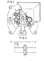
- Fig. 1 zeigt eine Draufsicht einer bekannten Durchgangsdose und
- Fig. 2 zeigt die Beschaltung der Dose nach Fig. 1 als Durchgangsdose nach dem Stand der Technik.
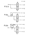
- Fig. 3 zeigt die Beschaltung der Dose nach Fig. 1 als Stichleitungsdose nach dem Stand der Technik.
- Fig. 4 zeigt die erfindungsgemäße Beschaltung der Dose nach Fig. 1 mit einem Leitungskoppler und
- Fig. 5 zeigt die erfindungsgemäße Beschaltung der Dose nach Fig. 1 mit einem Ubertragerkoppler.
- Fig. 1 zeigt die aus der eingangs genannten DE-PS 27 33 220 bekannte Antennensteckdose. Diese enthält einen ersten Anschluß 1 für ein erstes Koaxialkabel, eine erste Koaxial-Steckbuchse 2, eine zweite Koaxial-Steckbuchse 3 und einen zweiten Anschluß 4 für ein zweites Koaxialkabel. Die beiden Koaxialkabel befinden sich in der Darstellung unter einer Klappschelle. Die Hinweislinien von den Bezugszeichen 1 und 4 weisen auf Stellen, wo sich die Koaxialkabel unter der Klappschelle befinden.
- Fig. 2 zeigt die bekannte Beschaltung der Dose nach Fig. 1 als Durchgangsdose. Diese enthält einen Richtungskoppler 5 für 40 bis 860 MHz, ein Bandsperrfilter 6 für Hörrundfunk-Signale und ein Bandpaßfilter 7 für Hörrundfunk-Signale. Die Antennensignale durchlaufen die Dose unverändert vom Anschluß 1 zum Anschluß 4. An der Koaxial-Steckbuchse 2 liegen TV-Signale ohne Hörrundfunk-Signale und an der Koaxial-Steckbuchse 3 nur Hörrundfunk-Signale an.
- Fig. 3 zeigt die Beschaltung der Dose nach Fig. 1 als Stichleitungsdose. Im Gegensatz zur Schaltung nach Fig. 2 erübrigt sich der Richtungskoppler 5 und ein Koaxialkabel zur Antennensignalweiterleitung. Die Eingänge des Bandsperrfilters 6 und des Bandpaßfilters 7 sind unmittelbar mit dem Koaxialkabel-Anschluß 1 verbunden.
- Fig. 4 zeigt die erfindungsgemäße Beschaltung der Dose 1. Im Gegensatz zur Schaltung nach Fig. 3 ist zwischen den Koaxialkabel-Anschluß 1 und die Eingänge des Bandsperrfilters 6 und des Bandpaßfilters 7 ein Richtungskoppler 5' für 5 bis 860 MHz zwischengeschaltet. Der Ausgang der Auskoppelschleife des Richtungskopplers 5' ist mit dem Anschluß 4 verbunden.
- Der Anschluß 4 bietet jetzt eine Anschlußmöglichkeit für Geräte zusätzlicher Dienste, die sowohl in Rückrichtung Signale abgeben als ggf. auch aus der Anlagenverteilrichtung Zusatzsignale, wie beispielsweise trägerfrequente Digitalsignale zur Teilnehmeradressierung aufnehmen können.
- Vom Anschluß 4 kann eine Verbindung zu einem Modem hergestellt werden, das die Trägerfrequenz-Zusatzsignale der Abwärtsrichtung, die beispielsweise im Frequenzbereich 40 bis 860 MHz übertragen werden können, aufnimmt und trägerfrequente Zusatzrücksignale unterhalb 40 MHz in die Anlage einspeist. Der breitbandige Richtungskoppler 5' bietet den Vorteil der gegenseitigen Entkopplung von an die Koaxial-Steckbuchsen 2 und 3 angeschlossenen Fernseh (TV)- bzw. Hörrundfunkgeräten und dem Gerät für Zusatzdienste.
- Fig. 5 zeigt eine der Anordnung nach Fig. 4 entsprechende Anordnung mit einem Übertragerkoppler 5".
- Anstelle des Richtungskopplers 5' kann je nach Frequenzbelegung auch eine entsprechende Frequenzweichenschaltung treten.
Claims (3)
Priority Applications (1)
| Application Number | Priority Date | Filing Date | Title |
|---|---|---|---|
| AT81108593T ATE20407T1 (de) | 1981-03-06 | 1981-10-20 | Antennensteckdose. |
Applications Claiming Priority (2)
| Application Number | Priority Date | Filing Date | Title |
|---|---|---|---|
| DE3108621 | 1981-03-06 | ||
| DE19813108621 DE3108621A1 (de) | 1981-03-06 | 1981-03-06 | Antennensteckdose |
Publications (3)
| Publication Number | Publication Date |
|---|---|
| EP0059786A2 true EP0059786A2 (de) | 1982-09-15 |
| EP0059786A3 EP0059786A3 (en) | 1983-02-02 |
| EP0059786B1 EP0059786B1 (de) | 1986-06-11 |
Family
ID=6126556
Family Applications (1)
| Application Number | Title | Priority Date | Filing Date |
|---|---|---|---|
| EP81108593A Expired EP0059786B1 (de) | 1981-03-06 | 1981-10-20 | Antennensteckdose |
Country Status (3)
| Country | Link |
|---|---|
| EP (1) | EP0059786B1 (de) |
| AT (1) | ATE20407T1 (de) |
| DE (2) | DE3108621A1 (de) |
Cited By (2)
| Publication number | Priority date | Publication date | Assignee | Title |
|---|---|---|---|---|
| FR2656166A1 (fr) * | 1989-12-19 | 1991-06-21 | Desmotreux Yves | Boitier encadstrable sur prise specialisee liee a un dispositif de communication. |
| EP2573939A1 (de) * | 2011-09-20 | 2013-03-27 | Teleste Oyj | Multimedia Signalspalter |
Families Citing this family (2)
| Publication number | Priority date | Publication date | Assignee | Title |
|---|---|---|---|---|
| DE3723987A1 (de) * | 1987-07-20 | 1989-02-02 | Kathrein Werke Kg | Antennensteckdose |
| DE19813666A1 (de) * | 1998-03-27 | 1999-09-30 | Grundig Ag | Fernsehgerät mit HF-Signalaufspaltung innerhalb des Tuners |
Family Cites Families (3)
| Publication number | Priority date | Publication date | Assignee | Title |
|---|---|---|---|---|
| FR1286550A (fr) * | 1960-04-21 | 1962-03-02 | Siemens Ag | Dispositif de réception de télévision avec prise de raccordement pour appareils de télévision ou analogues sur des installations d'antennes |
| DE1286550B (de) * | 1967-07-12 | 1969-01-09 | Siemens Ag | Impulsprogramm-Generator |
| DE1801843A1 (de) * | 1968-10-08 | 1970-06-04 | Siemens Ag | Gemeinschaftsantennenanlage fuer den Empfang von Signalen im gesamten Rundfunk- und Fernsehbereich |
-
1981
- 1981-03-06 DE DE19813108621 patent/DE3108621A1/de not_active Withdrawn
- 1981-10-20 EP EP81108593A patent/EP0059786B1/de not_active Expired
- 1981-10-20 AT AT81108593T patent/ATE20407T1/de not_active IP Right Cessation
- 1981-10-20 DE DE8181108593T patent/DE3174816D1/de not_active Expired
Cited By (2)
| Publication number | Priority date | Publication date | Assignee | Title |
|---|---|---|---|---|
| FR2656166A1 (fr) * | 1989-12-19 | 1991-06-21 | Desmotreux Yves | Boitier encadstrable sur prise specialisee liee a un dispositif de communication. |
| EP2573939A1 (de) * | 2011-09-20 | 2013-03-27 | Teleste Oyj | Multimedia Signalspalter |
Also Published As
| Publication number | Publication date |
|---|---|
| DE3174816D1 (en) | 1986-07-17 |
| ATE20407T1 (de) | 1986-06-15 |
| EP0059786A3 (en) | 1983-02-02 |
| DE3108621A1 (de) | 1982-10-21 |
| EP0059786B1 (de) | 1986-06-11 |
Similar Documents
| Publication | Publication Date | Title |
|---|---|---|
| DE19702350B4 (de) | Zentralknoten-Konverter zur Verbindung mit einem Anschluss eines Haus-Netzwerks, das mit einem Koaxialkabel verbunden ist und Verfahren zur Kommunikation | |
| DE69334142T2 (de) | Übertragungsgerät zum Einsatz in einem Elektrizitäts-Verteilungsnetzwerk | |
| DE3874993T2 (de) | Einrichtung zur uebertragung von signalen, insbesondere von videosignalen. | |
| DE3852023T2 (de) | Kommunikationssystem für die Übertragung von Breitband- und Basisbandinformation. | |
| DE3586573T2 (de) | Signaluebertragungssystem und verfahren. | |
| EP1105947B1 (de) | Anordnung zur übermittlung von nachrichten über ein niederspannungs-stromversorgungsnetz sowie zwischenstück | |
| WO2001043238A1 (de) | Anordnung zur übermittlung von nachrichten über ein niederspannungs-stromversorgungsnetz | |
| EP0380945A2 (de) | Optisches Breitband-Nachrichtenübertragungssystem,insbesondere für den Teilnehmeranschlussbereich | |
| EP0059786B1 (de) | Antennensteckdose | |
| DE69814469T2 (de) | Passives kabelfernsehbauelement mit hf-verteiler und anschlussbuchse zur hinzufügung und wegnahme von leistung | |
| DE2316166B2 (de) | Gemeinschaftsantennenanlage mit Alarmgebern für die einzelnen Teilnehmer | |
| DE2111706C3 (de) | Schaltungsanordnung für eine Fernsprech-Vermittlungsanlage mit Pulsphasenmodulation | |
| EP0740434B1 (de) | System zur Verteilung von Fernsehsatellitensignalen in einer Gemeinschaftsantennenanlage | |
| DE3715594C2 (de) | Anordnung zum Anschluß von Ausgangs- und Eingangsstufen einer Sende/Empfangseinrichtung | |
| DE2339705C2 (de) | Fehlerortungssystem für Leitungsverstärker von Verstärkerstellen in einer Übertragungsstrecke | |
| DE69604693T2 (de) | Verbesserungen bei rundfunksignalbehandlung | |
| DE2906244C2 (de) | Eingangsanordnung für ein empfangsseitiges Leitungsendgerät eines Nachrichtenübertragungssystems | |
| EP0419713A1 (de) | Schnittstellenbaustein für eine Busschnittstelle | |
| DE68916751T2 (de) | Verstärkungssystem für Fernverteilung. | |
| DE69614072T2 (de) | Kabelnetzwerksystem für Videoverteilung und bidirektionale Datenübertragung, mit Freqenzumsetzung im Rückkanal | |
| EP0056448A2 (de) | Antennensteckdose | |
| DE1801843A1 (de) | Gemeinschaftsantennenanlage fuer den Empfang von Signalen im gesamten Rundfunk- und Fernsehbereich | |
| DE3031559C2 (de) | ||
| EP0398181B1 (de) | Vorrichtung zur Übertragung eines optischen Signals | |
| DE2461688C2 (de) |
Legal Events
| Date | Code | Title | Description |
|---|---|---|---|
| PUAI | Public reference made under article 153(3) epc to a published international application that has entered the european phase |
Free format text: ORIGINAL CODE: 0009012 |
|
| 17P | Request for examination filed |
Effective date: 19811020 |
|
| AK | Designated contracting states |
Designated state(s): AT BE CH DE NL |
|
| PUAL | Search report despatched |
Free format text: ORIGINAL CODE: 0009013 |
|
| AK | Designated contracting states |
Designated state(s): AT BE CH DE LI NL |
|
| GRAA | (expected) grant |
Free format text: ORIGINAL CODE: 0009210 |
|
| AK | Designated contracting states |
Kind code of ref document: B1 Designated state(s): AT BE CH DE LI NL |
|
| REF | Corresponds to: |
Ref document number: 20407 Country of ref document: AT Date of ref document: 19860615 Kind code of ref document: T |
|
| REF | Corresponds to: |
Ref document number: 3174816 Country of ref document: DE Date of ref document: 19860717 |
|
| PGFP | Annual fee paid to national office [announced via postgrant information from national office to epo] |
Ref country code: AT Payment date: 19861003 Year of fee payment: 6 |
|
| PLBE | No opposition filed within time limit |
Free format text: ORIGINAL CODE: 0009261 |
|
| STAA | Information on the status of an ep patent application or granted ep patent |
Free format text: STATUS: NO OPPOSITION FILED WITHIN TIME LIMIT |
|
| 26N | No opposition filed | ||
| PGFP | Annual fee paid to national office [announced via postgrant information from national office to epo] |
Ref country code: NL Payment date: 19871031 Year of fee payment: 7 |
|
| PG25 | Lapsed in a contracting state [announced via postgrant information from national office to epo] |
Ref country code: AT Effective date: 19881020 |
|
| PG25 | Lapsed in a contracting state [announced via postgrant information from national office to epo] |
Ref country code: LI Effective date: 19881031 Ref country code: CH Effective date: 19881031 Ref country code: BE Effective date: 19881031 |
|
| BERE | Be: lapsed |
Owner name: SIEMENS A.G. BERLIN UND MUNCHEN Effective date: 19881031 |
|
| PG25 | Lapsed in a contracting state [announced via postgrant information from national office to epo] |
Ref country code: NL Effective date: 19890501 |
|
| NLV4 | Nl: lapsed or anulled due to non-payment of the annual fee | ||
| REG | Reference to a national code |
Ref country code: CH Ref legal event code: PL |
|
| PG25 | Lapsed in a contracting state [announced via postgrant information from national office to epo] |
Ref country code: DE Effective date: 19890701 |