EP0058893B1 - Vorrichtung zur vertikalen Halterung mehrerer unabhängig voneinander verschwenkbarer Geräte - Google Patents
Vorrichtung zur vertikalen Halterung mehrerer unabhängig voneinander verschwenkbarer Geräte Download PDFInfo
- Publication number
- EP0058893B1 EP0058893B1 EP82101037A EP82101037A EP0058893B1 EP 0058893 B1 EP0058893 B1 EP 0058893B1 EP 82101037 A EP82101037 A EP 82101037A EP 82101037 A EP82101037 A EP 82101037A EP 0058893 B1 EP0058893 B1 EP 0058893B1
- Authority
- EP
- European Patent Office
- Prior art keywords
- rotary drive
- mast
- shaft
- hollow
- hollow shaft
- Prior art date
- Legal status (The legal status is an assumption and is not a legal conclusion. Google has not performed a legal analysis and makes no representation as to the accuracy of the status listed.)
- Expired
Links
- 230000015572 biosynthetic process Effects 0.000 claims 1
- 238000010276 construction Methods 0.000 description 4
- 230000000694 effects Effects 0.000 description 2
- 238000000034 method Methods 0.000 description 2
- 230000005540 biological transmission Effects 0.000 description 1
- 230000000295 complement effect Effects 0.000 description 1
- 238000009434 installation Methods 0.000 description 1
- 230000000717 retained effect Effects 0.000 description 1
Images
Classifications
-
- H—ELECTRICITY
- H01—ELECTRIC ELEMENTS
- H01Q—ANTENNAS, i.e. RADIO AERIALS
- H01Q3/00—Arrangements for changing or varying the orientation or the shape of the directional pattern of the waves radiated from an antenna or antenna system
- H01Q3/02—Arrangements for changing or varying the orientation or the shape of the directional pattern of the waves radiated from an antenna or antenna system using mechanical movement of antenna or antenna system as a whole
- H01Q3/04—Arrangements for changing or varying the orientation or the shape of the directional pattern of the waves radiated from an antenna or antenna system using mechanical movement of antenna or antenna system as a whole for varying one co-ordinate of the orientation
-
- H—ELECTRICITY
- H01—ELECTRIC ELEMENTS
- H01Q—ANTENNAS, i.e. RADIO AERIALS
- H01Q21/00—Antenna arrays or systems
- H01Q21/28—Combinations of substantially independent non-interacting antenna units or systems
Definitions
- the invention relates to a device for vertical mounting of several independently pivotable devices at the upper end of a mast, in particular antennas on an antenna mast, in which the devices are superimposed in the longitudinal direction of the mast and each device is assigned its own rotary drive.
- the invention has for its object to provide a device of the type mentioned, in which a largely coaxial and thus symmetrical design and arrangement of the rotary drives and the essential parts of the brackets for the devices allows and at the same time a simple structure and above all a simple assembly the entire mounting device is achieved on the mast, so as to reduce assembly work and set-up times as much as possible, especially for mobile devices.
- the rotary drives are arranged coaxially in that the non-rotatable part of the first rotary drive seen from the mast end is detachably connected at one end to the mast end and at the other end to a coaxial connecting support tube that the output shaft of this the first rotary drive is detachably connected to a hollow shaft rotatably mounted on the connection carrier tube, on which the carrier of the associated device is arranged, and that the non-rotatable part of the next following rotary drive is detachably connected to at least the preceding connection carrier tube and the output shaft of this rotary drive to the carrier or its Hollow shaft of the next device are connected.
- all detachable connections are designed as coaxial plug connections with a locking device.
- the respective structural units can be plugged into one another and locked or detached from one another in the shortest possible time.
- a design which is particularly expedient both in terms of the design and also in terms of assembly and disassembly is achieved in a further embodiment of the invention if the element of the non-rotatable part of the rotary drive connected to the connection carrier tube as one is formed by the hollow output shaft passed through the profile rod, which enters a complementarily profiled recess in the connection carrier tube during the establishment of the connection, and that the subsequent hollow shaft for the equipment carrier can be plugged onto the hollow output shaft with a hollow connecting piece, through which the profile rod is passed and on which supports the lower end of the hollow shaft. All required non-rotatable and rotating connections can be achieved in this way by simple plug-in processes and locking. This basic arrangement can also be repeated for more than two devices to be held.
- the drawing shows a mounting device which is used in particular for vertical mounting of several antennas which can be pivoted independently of one another at the upper end of an antenna mast, the antennas being mounted one above the other in the longitudinal direction of the mast as the devices to be held.
- the upper end of the support mast is designated 1 and has a receiving pipe socket 2, on which a suitable quick lock 3 is arranged for the subsequent connection. Seen from the upper mast end 1 follows a first rotary drive 4 in a suitable embodiment, for. B. an electric motor.
- the non-rotatable part here a non-rotatable connecting piece 5 can be inserted into the receiving pipe socket 2 and locked there via the quick lock 3.
- the non-rotatable part of the rotary drive 4 in particular the non-rotatable housing, is connected to the upper end 1 of the mast.
- the output shaft 6 of the rotary drive 4 is designed as a hollow shaft.
- a profile rod 7 is passed through this hollow output shaft 6 and protrudes in the longitudinal direction of the mast.
- This profile rod 7 thus maintains its position relative to the mast 1 while the hollow output shaft 6 rotates during operation of the rotary drive 4.
- the parts 5, 6 and 7 of the rotary drive 4 are thus arranged coaxially.
- a connection carrier tube 8 coaxial with this arrangement is a connection carrier tube 8, which continues upwards in the longitudinal direction of the mast.
- a hollow shaft 9 is rotatably supported, as indicated by the bearing 10 in Fig. 2.
- This hollow shaft 9 is connected at the lower end to a hollow connecting pipe socket 11 via a flange connection 12.
- connection carrier pipe 8 is supported at the lower end, while it extends further upward from the upper end of the hollow shaft 9 in the longitudinal direction of the mast.
- the carrier 13 for the respectively assigned device, for. B. an antenna.
- the connection carrier tube 8 has an annular disc 14, which is provided with a recess 15 which is complementary to the profile of the profile rod 7.
- the assembly formed from the connection carrier tube 8 and the hollow shaft 9 with the connection pipe socket 11 can be detachably connected to the first assembly formed from the rotary drive 4.
- the connecting pipe socket 11 of the hollow shaft 9 is pushed onto the hollow drive shaft 6 of the rotary drive 4.
- the profile rod 7 enters the recess 15 of the annular disk 14 of the connection carrier tube 8.
- connection carrier tube 8 is thus also connected in a rotationally fixed manner via 15, 7 and 5 to the upper end 1 of the supporting mast, while the hollow shaft 9 and thus the device attached to the carrier 13 , e.g. B. an antenna can be pivoted using the rotary drive 4.
- a suitable quick lock 16 on the connecting pipe socket 11 serves to lock the plug connection from FIGS. 6, 7, 11 and 15.
- the non-rotatable part 17 of the next rotary drive 18 is detachably connected, namely the non-rotatable part 17 of the rotary drive 18 is designed as a receptacle pipe socket and can be plugged onto the upper end of the connection carrier tube 8, with a suitable connection for locking this connector Quick lock 19 is used.
- the output shaft of the second rotary drive 18 is, as shown at 20, connected to the carrier of the next device, z. B. an antenna not shown here.
- the carrier 20 can be pivoted independently of the rotary movement of the hollow shaft 9.
- the rotary drive 18 and the rotary drive 4 as well as the unit consisting of connection carrier tube 8 and hollow shaft 9 are arranged coaxially to one another.
- the drawing shows the coaxial and thus axially symmetrical arrangement of the entire mounting device with the few exceptions that are insignificant with regard to the loads described, with the advantages described in detail at the beginning.
- the exemplary embodiment described shows the particularly simple assembly and disassembly of the entire mounting device, due to the coaxiality and the detachable, in particular as a plug Connections trained connections between the individual units is achieved.
Landscapes
- Support Of Aerials (AREA)
- Variable-Direction Aerials And Aerial Arrays (AREA)
- Mutual Connection Of Rods And Tubes (AREA)
Description
- Die Erfindung bezieht sich auf eine Vorrichtung zur vertikalen Halterung mehrerer unabhängig voneinander verschwenkbarer Geräte am oberen Ende eines Tragmastes, insbesondere von Antennen an einem Antennenmast, bei der die Geräte in Mastlängsrichtung übereinander gelagert sind und jedem Gerät ein eigener Drehantrieb zugeordnet ist.
- In der Praxis ist es häufig erforderlich, und zwar insbesondere bei Antennen an hohen Tragmasten, Geräte bzw. die Antennen sicher zu haltern, gleichzeitig aber unabhängig voneinander mit Hilfe eines eigenen Drehantriebs verschwenken zu können, im Fall der Antennen zur jeweiligen optimalen Ausrichtung. Dabei sind insbesondere zwei Probleme von Bedeutung: Einerseits führen Asymmetrien bei der Halterung und insbesondere bei der Anordnung der Drehantriebe insbesondere bei Tragmasten von größerer Höhe zu starken Belastungen, die durch etwaige Windlasten noch verstärkt werden. Zum anderen bringt eine aufwendige Montage einer derartigen Halterungsvorrichtung Nachteile mit sich, insbesondere im Fall eines mobilen Einsatzes des Tragmastes und der Halterungsvorrichtung, wie sie bei Antennenmasten häufig vorkommt. Es ist eine Vorrichtung der eingangs angegebenen Art bekannt (z. B. Prospekt »Salzgitter Antennenmast W 343-677-100 Gc), bei dem die Halterung ein Tragrohr aufweist, an dem über gesonderte plattformartige Halterungselemente Drehantriebe zum Verschwenken der Geräteträger außerhalb der Längsachse des Tragrohrs, also exzentrisch, angeordnet sind und über spezielle, jeweils gesondert zugeordnete Antriebselemente auf die Gerätehalterungen verschwenkend einwirken. Es handelt sich dabei um Halterungen von schwenkbaren Richtantennen. Diese bekannte Halterungsvorrichtung weist somit den Nachteil einer asymmetrischen Belastung des Tragrohrs und damit des Tragmastes bzw. Antennenmastes auf, die sich besonders bei größeren Windbelastungen sehr störned bemerkbar macht. Zum anderen ist die Montage der gesonderten Antriebe und Halterungen am Tragrohr sowohl von der Konstruktion als auch von der Montage sehr aufwendig, wodurch insbesondere bei mobilen Tragmasten die Aufbauzeiten erheblich verlängert werden.
- Der Erfindung liegt die Aufgabe zugrunde, eine Vorrichtung der eingangs angegebenen Art zu schaffen, bei der eine weitestgehend koaxiale und damit symmetrische Bauweise und Anordnung der Drehantriebe und der wesentlichen Teile der Halterungen für die Geräte ermöglicht und zugleich ein einfacher Aufbau und vor allem eine einfache Montage der gesamten Halterungsvorrichtung am Tragmast erzielt wird, um so insbesondere bei mobilen Einrichtungen die Montagearbeiten und die Aufbauzeiten weitestgehend zu verringern.
- Dies wird nach der Erfindung vor allem dadurch erreicht, daß die Drehantriebe koaxial angeordnet sind, daß der drehfeste Teil des vom Mastende gesehen ersten Drehantriebs lösbar an einem Ende mit dem Mastende und am anderen Ende mit einem koaxial verlaufenden Anschlußträgerrohr verbunden ist, daß die Abtriebswelle dieses ersten Drehantriebs lösbar mit einer auf dem Anschlußträgerrohr drehbar gelagerten Hohlwelle verbunden ist, an der der Träger des zugeordneten Geräts angeordnet ist, und daß der drehfeste Teil des jeweils nächstfolgenden Drehantriebs lösbar mit wenigstens dem vorausgehenden Anschlußträgerrohr und die Abtriebswelle dieses Drehantriebs mit dem Träger bzw. dessen Hohlwelle des nächstfolgenden Geräts verbunden sind. Hierdurch wird eine durchgehend koaxiale Bauweise und Anordnung sowohl der Drehantriebe wie auch der Übertragungselemente für die Verschwenkung der Geräte erreicht. Ferner wird ermöglicht, diese koaxiale Anordnung in einzelnen Baueinheiten zu montieren und zu demontieren. Denn es bilden der erste Drehantrieb, das Anschlußträgerrohr mit seiner Hohlwelle und dem Träger des zugeordneten Geräts sowie der nächstfolgende Drehantrieb jeweils einzelne Baueinheiten, die leicht gehandhabt und zusammengesetzt bzw. voneinander gelöst werden können. Auf diese Weise wird die geschilderte asymmetrische Belastung der Halterungsvorrichtung und damit des Tragmastes auf ein Mindestmaß herabgesetzt und die Montage erleichtert und somit die Aufbauzeit verringert. Sollen mehr als zwei Drehantriebe für mehr als zwei Geräte an der Halterungsvorrichtung angeordnet sein, so kann die gekennzeichnete Anordnungs- und Verbindungsweise für den ersten Drehantrieb im Anschluß an den zweiten Drehantrieb wiederholt werden. So kann an den drehfesten Teil des folgenden Drehantriebs ein weiteres folgendes, die Hohlwelle des zugehörigen Geräteträgers tragendes Anschlußträgerrohr angeschlossen und dieses dann mit dem drehfesten Teil eines weiteren folgenden Drehantriebs lösbar verbunden werden, der dann mit seiner Abtriebswelle auf den Träger des letzten Geräts einwirkt. Auch dabei bleibt die koaxiale und lösbare Anordnung der einzelnen Baueinheiten erhalten.
- Für die Vereinfachung der Montage und Demontage der Halterungsvorrichtung und damit für die weitere Verringerung der Aufbauzeit ist es zweckmäßig, wenn in weiterer Ausgestaltung der Erfindung sämtliche lösbaren Verbindungen als koaxiale Steckverbindungen mit Verriegelungseinrichtung ausgebildet sind. Hierdurch lassen sich in aller kürzester Zeit die jeweiligen Baueinheiten ineinanderstecken und miteinander verriegeln bzw. entsprechend voneinander lösen. Eine sowohl von der Bauweise als auch von der Montage und Demontage besonders zweckmäßige Bauform wird in weiterer Ausgestaltung der Erfindung erreicht, wenn das mit dem Anschlußträgerrohr verbundene Element des drehfesten Teils des Drehantriebs als ein durch dessen hohle Abtriebswelle hindurchgeführter Profilstab ausgebildet ist, der bei der Herstellung der Verbindung in eine komplementär profilierte Ausnehmung im Anschlußträgerrohr eintritt, und daß die nachfolgende Hohlwelle für den Geräteträger mit einem hohlen Anschlußrohrstutzen auf die Abtriebshohlwelle aufsteckbar ist, durch den der Profilstab hindurchgeführt ist und an dem sich das untere Ende der Hohlwelle abstützt. Sämtliche erforderlichen drehfesten und mitdrehenden Verbindungen lassen sich auf diese Weise durch einfache Steckvorgänge und Verriegelungen erreichen. Auch diese Grundanordnung kann bei mehr als zwei zu halternden Geräten wiederholt werden.
- Merkmale, weitere Vorteile und Einzelheiten ergeben sich aus den Ansprüchen und aus der nachfolgenden Beschreibung eines Ausführungsbeispiels der Erfindung anhand der Zeichnung. Es zeigt
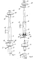
- Fig. 1 die zusammengesetzte und mit dem oberen Ende eines Tragmasts verbundene Halterungsvorrichtung nach der Erfindung ohne die zu halternden verschwenkbaren Geräte,
- Fig. 2 in explosionsartiger Darstellung die Halterungsvorrichtung nach Fig. 1 mit voneinander gelösten Baueinheiten,
- Die Zeichnung zeigt eine Halterungsvorrichtung, die insbesondere zur vertikalen Halterung mehrerer unabhängig voneinander verschwenkbarer Antennen am oberen Ende eines Antennenmastes dient, wobei die Antennen als die zu halternden Geräte in Mastlängsrichtung übereinander gelagert sind.
- Das obere Ende des Tragmasts ist mit 1 bezeichnet und weist einen Aufnahmerohrstutzen 2 auf, an dem eine geeignete Schnellverriegelung 3 für die nachfolgende Verbindung angeordnet ist. Vom oberen Mastende 1 her gesehen folgt ein erster Drehantrieb 4 in geeigneter Ausgestaltung, z. B. ein Elektromotor. Der drehfeste Teil, hier ein drehfester Anschlußstutzen 5 läßt sich in den Aufnahmerohrstutzen 2 einstecken und dort über die Schnellverriegelung 3 verriegeln. Somit ist der drehfeste Teil des Drehantriebs 4, insbesondere das drehfeste Gehäuse, mit dem oberen Ende 1 des Tragmastes verbunden. Die Abtriebswelle 6 des Drehantriebs 4 ist als Hohlwelle ausgeführt. Als Element des drehfesten Teils des Drehantriebs ist durch diese hohle Abtriebswelle 6 ein Profilstab 7 hindurchgeführt und ragt in Mastlängsrichtung hervor. Dieser Profilstab 7 erhält also seine Lage gegenüber dem Tragmast 1 bei, während sich die Abtriebshohlwelle 6 im Betrieb des Drehantriebs 4 dreht. Die Teile 5, 6 und 7 des Drehantriebs 4 sind somit koaxial angeordnet. Ebenfalls koaxial zu dieser Anordnung verläuft ein Anschlußträgerrohr 8, das sich in Mastlängsrichtung nach oben fortsetzt. Auf diesem Anschlußträgerrohr 8 ist eine Hohlwelle 9 drehbar gelagert, wie durch die Lager 10 in Fig. 2 angedeutet ist. Diese Hohlwelle 9 ist am unteren Ende mit einem hohlen Anschlußrohrstutzen 11 über eine Flanschverbindung 12 verbunden. In diesem Anschlußrohrstutzen 11 stützt sich das Anschlußträgerrohr 8 am unteren Ende ab, während es sich aus dem oberen Ende der Hohlwelle 9 in Mastlängsrichtung nach oben weiter erstreckt. An der Hohlwelle 9 ist der Träger 13 für das jeweils zugeordnete Gerät, z. B. eine Antenne, angeordnet. Im unteren Ende weist das Anschlußträgerrohr 8 eine Ringscheibe 14 auf, die mit einer zum Profil des Profilstabs 7 komplementären Ausnehmung 15 versehen ist. Die aus dem Anschlußträgerrohr 8 und der Hohlwelle 9 mit dem Anschlußrohrstutzen 11 gebildete Baueinheit ist lösbar mit der aus dem Drehantrieb 4 gebildeten ersten Baueinheit verbindbar. Dazu wird der Anschlußrohrstutzen 11 der Hohlwelle 9 auf die Antriebshohlwelle 6 des Drehantriebs 4 aufgeschoben. Dabei tritt der Profilstab 7 in die Ausnehmung 15 der Ringscheibe 14 des Anschlußträgerrohrs 8. Das Anschlußträgerrohr 8 ist somit ebenfalls drehfest über 15, 7 und 5 mit dem oberen Ende 1 des Tragmastes verbunden, während die Hohlwelle 9 und damit das am Träger 13 befestigte Gerät, z. B. eine Antenne, mit Hilfe des Drehantriebs 4 verschwenkt werden kann. Zur Verriegelung der Steckverbindung aus 6, 7, 11 und 15 dient eine geeignete Schnellverriegelung 16 am Anschlußrohrstutzen 11.
- Mit dem oberen Ende des drehfesten Anschlußträgerrohrs 8 ist der drehfeste Teil 17 des nächstfolgenden Drehantriebs 18 lösbar verbunden, und zwar ist der drehfeste Teil 17 des Drehantriebs 18 als Aufnahmerohrstutzen ausgebildet und auf das obere Ende des Anschlußträgerrohrs 8 aufsteckbar, wobei zur Verriegelung dieser Steckverbindung eine geeignete Schnellverriegelung 19 dient. Die Abtriebswelle des zweiten Drehantriebs 18 ist, wie bei 20 dargestellt ist, mit dem Träger des nächstfolgenden Geräts verbunden, z. B. einer hier nicht weiter dargestellten Antenne. Somit kann mit Hilfe des Drehantriebs 18 der Träger 20 unabhängig von der Drehbewegung der Hohlwelle 9 verschwenkt werden.
- Aus Beschreibung und Zeichnung ist ersichtlich, daß an Stelle der in der Zeichnung dargestellten Ausbildung des Drehantriebs 18 mit dem direkten Antrieb des Trägers 20 eine dem Drehantrieb 4 und der nachfolgenden Baueinheit aus Anschlußträgerrohr 8 und Hohlwelle 9 bestehende Konstruktion wiederholt eingeschaltet werden kann, wenn mehr als zwei Geräte unabhängig voneinander schwenkbar durch die Halterungsvorrichtung getragen werden sollen.
- Der Drehantrieb 18 und der Drehantrieb 4 sowie die Baueinheit aus Anschlußträgerrohr 8 und Hohlwelle 9 sind koaxial zueinander angeordnet. Die Zeichnung zeigt die mit ganz wenigen, hinsichtlich der geschilderten Belastungen unerheblichen Ausnahmen koaxiale und damit axial symmetrische Anordnung der gesamten Halterungsvorrichtung mit den eingangs eingehend geschilderten Vorteilen. Zum anderen zeigt das geschilderte Ausführbeispiel die besonders einfache Montage und Demontage der gesamten Halterungsvorrichtung, die durch die Koaxialität und durch die lösbaren, insbesondere als Steckverbindungen ausgebildeten Verbindungen zwischen den einzelnen Baueinheiten erreicht wird.
beide Darstellungen in der Seitenansicht.
Claims (3)
Applications Claiming Priority (2)
| Application Number | Priority Date | Filing Date | Title |
|---|---|---|---|
| DE19818105223U DE8105223U1 (de) | 1981-02-25 | 1981-02-25 | Vorrichtung zur vertikalen halterung mehrerer unabhaengig voneinander verschwenkbarer geraete |
| DE8105223U | 1981-02-25 |
Publications (2)
| Publication Number | Publication Date |
|---|---|
| EP0058893A1 EP0058893A1 (de) | 1982-09-01 |
| EP0058893B1 true EP0058893B1 (de) | 1984-10-31 |
Family
ID=6725028
Family Applications (1)
| Application Number | Title | Priority Date | Filing Date |
|---|---|---|---|
| EP82101037A Expired EP0058893B1 (de) | 1981-02-25 | 1982-02-12 | Vorrichtung zur vertikalen Halterung mehrerer unabhängig voneinander verschwenkbarer Geräte |
Country Status (4)
| Country | Link |
|---|---|
| US (1) | US4491846A (de) |
| EP (1) | EP0058893B1 (de) |
| JP (1) | JPS581303A (de) |
| DE (2) | DE8105223U1 (de) |
Families Citing this family (9)
| Publication number | Priority date | Publication date | Assignee | Title |
|---|---|---|---|---|
| DE3120112A1 (de) * | 1981-05-20 | 1982-12-09 | Precitronic Gesellschaft für Feinmechanik und Electronic mbH, 2000 Hamburg | Sende-, empfangs- und/oder messeinrichtung mit mehrfachfunktion |
| FR2555820B1 (fr) * | 1983-11-28 | 1987-09-04 | Lerc Lab Etudes Rech Chim | Mat pouvant supporter au moins deux dispositifs orientables et elements constituant ce mat |
| US4647936A (en) * | 1984-09-26 | 1987-03-03 | Ting-I Lin | Slewing assembly |
| US5446472A (en) * | 1993-11-30 | 1995-08-29 | Winegard Company | System for raising and lowering an antenna |
| FR2775834B1 (fr) * | 1998-03-04 | 2000-05-12 | Texas De France | Dispositif motorise a deux positions d'orientation d'antennes satellites |
| US8317151B1 (en) * | 2011-07-28 | 2012-11-27 | The United States Of America As Represented By The Secretary Of The Navy | Mounting bracket for GPS antenna |
| EP3352295A1 (de) * | 2017-01-18 | 2018-07-25 | BAE SYSTEMS plc | Antennenanordnung |
| GB2557629A (en) * | 2016-12-13 | 2018-06-27 | Bae Systems Plc | Antenna arrangement |
| CN115697848A (zh) * | 2020-06-10 | 2023-02-03 | 索尼集团公司 | 着陆装置 |
Family Cites Families (6)
| Publication number | Priority date | Publication date | Assignee | Title |
|---|---|---|---|---|
| US3146452A (en) * | 1953-06-10 | 1964-08-25 | Joseph K Rose | Remotely operated hand crank and gear drive for orientation of antennas on a mast |
| US2981834A (en) * | 1955-01-11 | 1961-04-25 | Rollind O Holloway | Interference rejection system and method using two relatively rotatable antennas |
| DE1289563B (de) * | 1965-09-10 | 1969-02-20 | S M A Segnalamento Marittimo E | Radarantennenanlage mit zwei oder mehr uebereinander angeordneten Antennen |
| US3742358A (en) * | 1970-12-30 | 1973-06-26 | R Cesaro | Tethered airborne communications and information transfer system |
| US3728733A (en) * | 1972-02-24 | 1973-04-17 | J Robinson | Beam antenna selectively oriented to vertical or horizontal position |
| DE2829116A1 (de) * | 1978-07-03 | 1980-01-17 | Wilhelm Kroes | Antennenmast |
-
1981
- 1981-02-25 DE DE19818105223U patent/DE8105223U1/de not_active Expired
-
1982
- 1982-02-12 EP EP82101037A patent/EP0058893B1/de not_active Expired
- 1982-02-12 DE DE8282101037T patent/DE3261089D1/de not_active Expired
- 1982-02-12 US US06/348,458 patent/US4491846A/en not_active Expired - Fee Related
- 1982-02-24 JP JP57028692A patent/JPS581303A/ja active Pending
Also Published As
| Publication number | Publication date |
|---|---|
| DE8105223U1 (de) | 1981-09-10 |
| DE3261089D1 (en) | 1984-12-06 |
| EP0058893A1 (de) | 1982-09-01 |
| US4491846A (en) | 1985-01-01 |
| JPS581303A (ja) | 1983-01-06 |
Similar Documents
| Publication | Publication Date | Title |
|---|---|---|
| DE69621585T2 (de) | Vorrichtung zum auswechseln von brennern | |
| CH661155A5 (de) | Mobile transformatoren-unterstation. | |
| DE69834659T2 (de) | Tragpfosten für eine flexible führungsschiene | |
| DE3337344A1 (de) | Tragbare schlauchwickelvorrichtung, insbesondere fuer wagen, caravans, omnibusse, schiffe, balkone und kleine gaerten | |
| DE2915897A1 (de) | Scher-biege-vorrichtung zur bearbeitung der anschlussleitungen von elektrischen bauelementen | |
| CH635393A5 (en) | Apparatus for protection against solar radiation and/or weather influences | |
| EP1235965B1 (de) | Verteilermast für betonpumpen | |
| EP0058893A1 (de) | Vorrichtung zur vertikalen Halterung mehrerer unabhängig voneinander verschwenkbarer Geräte | |
| DE4132998C2 (de) | Ansaug- und Transportvorrichtung | |
| WO2009080224A1 (de) | Führungseinrichtung für tauchmotorrührwerke | |
| EP0123785B1 (de) | Bandfördereinrichtung | |
| DE3939969A1 (de) | Schlauch- und kabelwindeanordnung einer gesteinsbohrvorrichtung | |
| DE1784444C3 (de) | Strahlrohr mit schwenkbarem Mündungsteil | |
| EP0178458B1 (de) | Wickelvorrichtung | |
| EP0454662B1 (de) | Rohrpoststation | |
| DE2814100A1 (de) | Vorrichtung zum ablaengen, sicken und/oder biegen der anschlussdraehte von elektrischen bauelementen | |
| DE2530105A1 (de) | Bodenbearbeitungsmaschine | |
| DE102005007114B4 (de) | Masthalter | |
| EP0009680A1 (de) | Stahlrohrgerüst | |
| EP0296407B1 (de) | Vorrichtung zur Axialverschiebung von Walzenlagerträgern | |
| DE3125593A1 (de) | Antennenhalterung | |
| DE7616358U1 (de) | Vorrichtung zum ausklinken von rohren | |
| DE19909758C2 (de) | Fahrgestell für Putzfördergeräte | |
| DE3640111C2 (de) | ||
| DE3320056C1 (de) | Befestigungsvorrichtung für das Lagergehäuse einer Spinn- oder Zwirnspindellagerung in der Spindelbank einer Maschine |
Legal Events
| Date | Code | Title | Description |
|---|---|---|---|
| PUAI | Public reference made under article 153(3) epc to a published international application that has entered the european phase |
Free format text: ORIGINAL CODE: 0009012 |
|
| AK | Designated contracting states |
Designated state(s): BE DE FR GB IT NL SE |
|
| 17P | Request for examination filed |
Effective date: 19821007 |
|
| GRAA | (expected) grant |
Free format text: ORIGINAL CODE: 0009210 |
|
| AK | Designated contracting states |
Designated state(s): BE DE FR GB IT NL SE |
|
| PG25 | Lapsed in a contracting state [announced via postgrant information from national office to epo] |
Ref country code: SE Effective date: 19841031 Ref country code: IT Free format text: LAPSE BECAUSE OF FAILURE TO SUBMIT A TRANSLATION OF THE DESCRIPTION OR TO PAY THE FEE WITHIN THE PRESCRIBED TIME-LIMIT;WARNING: LAPSES OF ITALIAN PATENTS WITH EFFECTIVE DATE BEFORE 2007 MAY HAVE OCCURRED AT ANY TIME BEFORE 2007. THE CORRECT EFFECTIVE DATE MAY BE DIFFERENT FROM THE ONE RECORDED. Effective date: 19841031 |
|
| REF | Corresponds to: |
Ref document number: 3261089 Country of ref document: DE Date of ref document: 19841206 |
|
| ET | Fr: translation filed | ||
| PG25 | Lapsed in a contracting state [announced via postgrant information from national office to epo] |
Ref country code: BE Effective date: 19850228 |
|
| BERE | Be: lapsed |
Owner name: SALZGITTER MASCHINEN UND ANLAGEN A.G. Effective date: 19850212 |
|
| PG25 | Lapsed in a contracting state [announced via postgrant information from national office to epo] |
Ref country code: NL Effective date: 19850901 |
|
| PLBE | No opposition filed within time limit |
Free format text: ORIGINAL CODE: 0009261 |
|
| STAA | Information on the status of an ep patent application or granted ep patent |
Free format text: STATUS: NO OPPOSITION FILED WITHIN TIME LIMIT |
|
| NLV4 | Nl: lapsed or anulled due to non-payment of the annual fee | ||
| 26N | No opposition filed | ||
| GBPC | Gb: european patent ceased through non-payment of renewal fee |
Free format text: INSERT JOURNAL 5094,PAGE 5702 |
|
| PG25 | Lapsed in a contracting state [announced via postgrant information from national office to epo] |
Ref country code: GB Free format text: LAPSE BECAUSE OF NON-PAYMENT OF DUE FEES Effective date: 19881121 |
|
| PGFP | Annual fee paid to national office [announced via postgrant information from national office to epo] |
Ref country code: FR Payment date: 19891222 Year of fee payment: 9 |
|
| PGFP | Annual fee paid to national office [announced via postgrant information from national office to epo] |
Ref country code: DE Payment date: 19900301 Year of fee payment: 9 |
|
| PG25 | Lapsed in a contracting state [announced via postgrant information from national office to epo] |
Ref country code: FR Effective date: 19911031 |
|
| PG25 | Lapsed in a contracting state [announced via postgrant information from national office to epo] |
Ref country code: DE Effective date: 19911101 |
|
| REG | Reference to a national code |
Ref country code: FR Ref legal event code: ST |