EP0057378B1 - Schaltungsanordnung für einen Schrittmotor - Google Patents
Schaltungsanordnung für einen Schrittmotor Download PDFInfo
- Publication number
- EP0057378B1 EP0057378B1 EP19820100397 EP82100397A EP0057378B1 EP 0057378 B1 EP0057378 B1 EP 0057378B1 EP 19820100397 EP19820100397 EP 19820100397 EP 82100397 A EP82100397 A EP 82100397A EP 0057378 B1 EP0057378 B1 EP 0057378B1
- Authority
- EP
- European Patent Office
- Prior art keywords
- thyristor
- capacitor
- winding
- series
- current source
- Prior art date
- Legal status (The legal status is an assumption and is not a legal conclusion. Google has not performed a legal analysis and makes no representation as to the accuracy of the status listed.)
- Expired
Links
Images
Classifications
-
- H—ELECTRICITY
- H02—GENERATION; CONVERSION OR DISTRIBUTION OF ELECTRIC POWER
- H02P—CONTROL OR REGULATION OF ELECTRIC MOTORS, ELECTRIC GENERATORS OR DYNAMO-ELECTRIC CONVERTERS; CONTROLLING TRANSFORMERS, REACTORS OR CHOKE COILS
- H02P8/00—Arrangements for controlling dynamo-electric motors rotating step by step
- H02P8/14—Arrangements for controlling speed or speed and torque
Definitions
- the invention relates to a circuit arrangement for a stepper motor, the stator windings of which can be switched on and off with a thyristor in series with a constant current source.
- Such circuits can be used, for example, to drive the printing unit in teletype machines.
- a stepping motor with a relatively low self-holding torque has the advantage of a correspondingly low energy requirement for carrying out each step.
- the self-holding torque can be supported by an additional magnetic field, which can be generated by a current flowing in a stator winding in the idle state.
- stator windings are switched on by means of the thyristors in series, the conductive state of which is maintained by the current flowing through them.
- the associated thyristor To switch off a stator winding, the associated thyristor must be blocked, which usually requires a special quenching device. It is advantageous if one can use the thyristor of a stator winding to be switched on to delete a thyristor.
- the invention has for its object to provide a particularly simple circuit arrangement with thyristors with which a current flowing in a stator winding of a stepper motor can be switched as quickly and with little loss to another winding and in which the thyristor of the winding to be switched on acts as an extinguishing thyristor of the previously ignited thyristor .
- the movable element of such a motor also not shown, as a rule the rotor, assumes a position corresponding to the windings that are respectively controlled.
- the magnetic field of a current-carrying winding acts on the rotor.
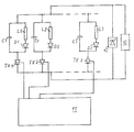
- the windings L1, L2, L3 can be connected to the power supply 10 with the associated thyristors Th1, Th2, Th3 which are connected in series.
- a constant current source is used as the energy supply 10.
- an overvoltage protection 12 is provided to prevent harmful overvoltages at the output terminals of the constant current source 10.
- the ignition pulses for the control electrodes of the thyristors Th1, Th2, Th3 are generated by a control module 11.
- Diodes D1, D2, D3 are in series with the windings L1, L2, L3.
- Capacitors C1, C2, C3 are connected in parallel with the series circuits formed therefrom.
- the voltage generated by constant current source 10 is initially limited to the value specified by overvoltage protection 12 because there are no open current paths in the connected circuit as long as thyristors Th1, Th2, Th3 are blocked.
- the capacitors C1, C2, C3 are initially uncharged.
- the thyristor Th2 is ignited. Through this thyristor Th2, the current flows into the capacitor C2, so that the voltage from the constant current source 10 breaks down. With increasing charge of the capacitor C2, the voltage rises again.
- the current flows through the still uncharged capacitor C1, as a result of which the voltage at the constant current source 10 breaks down and the thyristor Th2 blocks.
- the process already described for thyristor Th2 takes place in the circuit belonging to thyristor Th1 and generates the desired magnetic field in winding L1.
- the voltage across the capacitor C2 acts as a counter voltage, to which the voltage from the constant current source 10 drops, so that the previously fired thyristor Th1 blocks particularly quickly and reliably.
Landscapes
- Engineering & Computer Science (AREA)
- Power Engineering (AREA)
- Control Of Stepping Motors (AREA)
Applications Claiming Priority (2)
| Application Number | Priority Date | Filing Date | Title |
|---|---|---|---|
| DE3103097 | 1981-01-30 | ||
| DE19813103097 DE3103097C2 (de) | 1981-01-30 | 1981-01-30 | Schaltungsanordnung für einen Schrittmotor |
Publications (2)
| Publication Number | Publication Date |
|---|---|
| EP0057378A1 EP0057378A1 (de) | 1982-08-11 |
| EP0057378B1 true EP0057378B1 (de) | 1984-03-28 |
Family
ID=6123649
Family Applications (1)
| Application Number | Title | Priority Date | Filing Date |
|---|---|---|---|
| EP19820100397 Expired EP0057378B1 (de) | 1981-01-30 | 1982-01-21 | Schaltungsanordnung für einen Schrittmotor |
Country Status (5)
| Country | Link |
|---|---|
| EP (1) | EP0057378B1 (OSRAM) |
| JP (1) | JPS57145598A (OSRAM) |
| CA (1) | CA1190278A (OSRAM) |
| DE (1) | DE3103097C2 (OSRAM) |
| IN (1) | IN156138B (OSRAM) |
Families Citing this family (2)
| Publication number | Priority date | Publication date | Assignee | Title |
|---|---|---|---|---|
| RU2136104C1 (ru) * | 1997-01-16 | 1999-08-27 | Калабурдин Виктор Иванович | Электропривод транспортных средств с автономными источниками питания |
| JP4875777B1 (ja) * | 2011-05-19 | 2012-02-15 | アタカ大機株式会社 | 曝気攪拌装置 |
Family Cites Families (8)
| Publication number | Priority date | Publication date | Assignee | Title |
|---|---|---|---|---|
| GB950337A (en) * | 1961-06-15 | 1964-02-26 | Int Computers & Tabulators Ltd | Improvements in or relating to switching apparatus for inductive circuits |
| US3247433A (en) * | 1962-12-12 | 1966-04-19 | Bendix Corp | Reversible silicon controlled rectifier ring counter for stepper motor drive |
| GB1010571A (en) * | 1963-01-24 | 1965-11-17 | Ass Elect Ind | Improvements in or relating to the speed control of electric motors |
| US3392293A (en) * | 1964-12-29 | 1968-07-09 | Teletype Corp | Electromagnetic stepping motor |
| GB1112455A (en) * | 1966-08-03 | 1968-05-08 | Kabushikikaisha Tokyo Keiki Se | Power source device for driving step motor of gyro |
| CA902167A (en) * | 1967-09-22 | 1972-06-06 | Fairchild Camera And Instrument Corporation | Stepper motor control system |
| DE2009752C3 (de) * | 1969-03-07 | 1975-03-06 | Institutul Politehnic, Cluj (Rumaenien) | Schaltungsanordnung zur Steuerung der Drehzahl eines Drehstrom-Asynchronmotors |
| DE2829685C2 (de) * | 1978-07-06 | 1982-09-09 | Danfoss A/S, 6430 Nordborg | Mit Gleichspannung gespeister Motor |
-
1981
- 1981-01-30 DE DE19813103097 patent/DE3103097C2/de not_active Expired
-
1982
- 1982-01-21 EP EP19820100397 patent/EP0057378B1/de not_active Expired
- 1982-01-29 JP JP1194982A patent/JPS57145598A/ja active Pending
- 1982-01-29 CA CA000395230A patent/CA1190278A/en not_active Expired
- 1982-03-01 IN IN236/CAL/82A patent/IN156138B/en unknown
Also Published As
| Publication number | Publication date |
|---|---|
| EP0057378A1 (de) | 1982-08-11 |
| CA1190278A (en) | 1985-07-09 |
| DE3103097C2 (de) | 1985-01-24 |
| DE3103097A1 (de) | 1982-08-12 |
| IN156138B (OSRAM) | 1985-05-18 |
| JPS57145598A (en) | 1982-09-08 |
Similar Documents
| Publication | Publication Date | Title |
|---|---|---|
| DE2258288C2 (de) | Zündanlage für Brennkraftmaschinen | |
| DE68904207T2 (de) | Zuendsystem. | |
| DE1539222B1 (de) | Funkenzuendschaltung fuer brennkraftmaschinen | |
| DE2242334A1 (de) | Gleichstromsteuerschaltung | |
| EP0057378B1 (de) | Schaltungsanordnung für einen Schrittmotor | |
| DE2530910B2 (de) | Schutzvorrichtung für einen oder mehrere Reihenkondensatoren oder Reihenkondensatorgruppen | |
| DE2418265A1 (de) | Zuendanlage fuer brennkraftmaschinen | |
| DE2003659A1 (de) | Stromrichter mit Thyristorventilen | |
| DE2031862A1 (de) | Schaltanordnung zur Steuerung eines Elektromotors | |
| DD158156A5 (de) | Vom wechselstromnetz gespeister,in beiden drehrichtungen bremsbarer umkehrantrieb | |
| DE3309248A1 (de) | Ueberspannungsschutzschaltung fuer impulsmodulatoren und modulator fuer radareinrichtungen mit einer solchen ueberspannungsschutzschaltung | |
| DE2016198A1 (de) | Schaltungsanordnung zur Steuerung von elektrischen Schrittmotoren bzw Schritt magnetanordnungen | |
| DE1539222C (de) | Funkenzundschaltung fur Brennkraft maschinen | |
| DE2013043C3 (OSRAM) | ||
| DE1613234B2 (de) | Schaltungsanordnung zur steuerung des stromflusses in einer belastung | |
| DE1539375B1 (de) | Zuendschaltung fuer Entladungslampen | |
| DE2014217A1 (de) | Steuerschaltung fur Schalttransistoren | |
| DE3335222A1 (de) | Verfahren zur ansteuerung eines selbstgefuehrten wechselrichters | |
| DE3119889C1 (de) | Schutzschaltung für einen Thyristor in einem Kondensator-Thyristorschalter | |
| AT304705B (de) | Schaltungsanordnung mit zwei je in Serei einen gesonderten Lastwiderstand und eine steuerbare Ventilstrecke enthaltenden, abwechselnd stromführenden Gleichstromkreisen | |
| DE3143622A1 (de) | Schaltungsanordnung zur kompensation elektrischer blindleistung in einem stromnetz | |
| DE1464050C3 (de) | Transistorisierte Zündeinrichtung für Brennkraftmaschinen | |
| AT240476B (de) | Gitterspannungsgerät für Ionenventile | |
| AT267004B (de) | Stromversorgungsanlage mit zur Gleichstromschweißung und zur Batterieladung parallel liegenden Ausgangsklemmen | |
| DE2843255A1 (de) | Batterieladesystem |
Legal Events
| Date | Code | Title | Description |
|---|---|---|---|
| PUAI | Public reference made under article 153(3) epc to a published international application that has entered the european phase |
Free format text: ORIGINAL CODE: 0009012 |
|
| AK | Designated contracting states |
Designated state(s): CH FR GB LI SE |
|
| 17P | Request for examination filed |
Effective date: 19820702 |
|
| RAP1 | Party data changed (applicant data changed or rights of an application transferred) |
Owner name: FELTEN & GUILLEAUME FERNMELDEANLAGEN GMBH |
|
| GRAA | (expected) grant |
Free format text: ORIGINAL CODE: 0009210 |
|
| AK | Designated contracting states |
Designated state(s): CH FR GB LI SE |
|
| ET | Fr: translation filed | ||
| PLBE | No opposition filed within time limit |
Free format text: ORIGINAL CODE: 0009261 |
|
| STAA | Information on the status of an ep patent application or granted ep patent |
Free format text: STATUS: NO OPPOSITION FILED WITHIN TIME LIMIT |
|
| 26N | No opposition filed | ||
| PGFP | Annual fee paid to national office [announced via postgrant information from national office to epo] |
Ref country code: GB Payment date: 19920102 Year of fee payment: 11 |
|
| PGFP | Annual fee paid to national office [announced via postgrant information from national office to epo] |
Ref country code: CH Payment date: 19920422 Year of fee payment: 11 |
|
| PGFP | Annual fee paid to national office [announced via postgrant information from national office to epo] |
Ref country code: FR Payment date: 19930120 Year of fee payment: 12 |
|
| PG25 | Lapsed in a contracting state [announced via postgrant information from national office to epo] |
Ref country code: GB Effective date: 19930121 |
|
| PGFP | Annual fee paid to national office [announced via postgrant information from national office to epo] |
Ref country code: SE Payment date: 19930127 Year of fee payment: 12 |
|
| PG25 | Lapsed in a contracting state [announced via postgrant information from national office to epo] |
Ref country code: LI Effective date: 19930131 Ref country code: CH Effective date: 19930131 |
|
| GBPC | Gb: european patent ceased through non-payment of renewal fee |
Effective date: 19930121 |
|
| REG | Reference to a national code |
Ref country code: CH Ref legal event code: PL |
|
| PG25 | Lapsed in a contracting state [announced via postgrant information from national office to epo] |
Ref country code: SE Effective date: 19940122 |
|
| PG25 | Lapsed in a contracting state [announced via postgrant information from national office to epo] |
Ref country code: FR Effective date: 19940930 |
|
| REG | Reference to a national code |
Ref country code: FR Ref legal event code: ST |
|
| EUG | Se: european patent has lapsed |
Ref document number: 82100397.7 Effective date: 19940810 |