EP0055837A1 - Light vehicle - Google Patents
Light vehicle Download PDFInfo
- Publication number
- EP0055837A1 EP0055837A1 EP19810110492 EP81110492A EP0055837A1 EP 0055837 A1 EP0055837 A1 EP 0055837A1 EP 19810110492 EP19810110492 EP 19810110492 EP 81110492 A EP81110492 A EP 81110492A EP 0055837 A1 EP0055837 A1 EP 0055837A1
- Authority
- EP
- European Patent Office
- Prior art keywords
- steering
- control column
- frame part
- wheel
- wheel vehicle
- Prior art date
- Legal status (The legal status is an assumption and is not a legal conclusion. Google has not performed a legal analysis and makes no representation as to the accuracy of the status listed.)
- Granted
Links
Images
Classifications
-
- B—PERFORMING OPERATIONS; TRANSPORTING
- B62—LAND VEHICLES FOR TRAVELLING OTHERWISE THAN ON RAILS
- B62K—CYCLES; CYCLE FRAMES; CYCLE STEERING DEVICES; RIDER-OPERATED TERMINAL CONTROLS SPECIALLY ADAPTED FOR CYCLES; CYCLE AXLE SUSPENSIONS; CYCLE SIDE-CARS, FORECARS, OR THE LIKE
- B62K21/00—Steering devices
Definitions
- the invention relates to a multi-wheel vehicle, namely a light vehicle, the front wheel of which is driven by pedal drive, or which acts on the front wheel or the rear wheels in the case of the motor power drive. It can be used as a means of transportation, as a shopping trolley or as a transport trolley, for example for newspaper carriers.
- Light vehicles of the type described on the market have the basic construction of the bicycle, in particular with regard to the frame. Such vehicles have a number of parts that are far apart and therefore must be connected to each other by the frame. (Wheel bearings, steering bearings, bottom bracket and seat post). There are several to connect these parts
- the object of the invention is to simplify the frame of such a vehicle and thus to make the vehicle easier.
- the material required and the amount of work required to manufacture the vehicle are to be reduced. This reduction is possible when the construction is formed so that the triangle frame, which connects the control bearing, Tret l carrier and seat post, is in elimination.
- the above-identified object is achieved according to the invention in that the steering axis is arranged in the front frame part behind the control column, that a rearwardly extending reduction rod is arranged on the control column and that the steering axis rotatably with a extending rearward, at its rear free end carrying the central part of the handlebar is connected, which run in a parallel to the plane of the reduction rod the level lies, wherein the transmission lever and the reduction rod are necessarily slidably coupled to one another via a connecting bolt.
- a clamp receiving a saddle is arranged on the reduction rod between the steering axis and the control column in accordance with a development of the invention; the front frame part then forms an approximately U-shaped, downwardly open frame together with a rear frame part assigned to it.
- the bottom bracket of the pedal drive is located outside the front wheel and behind its axle.
- the seat surface is fixed to the front frame part.
- the handlebar it is advisable to design the handlebar so that it has grip parts that extend obliquely to the front and upwards.
- the construction according to the invention of a multi-wheel vehicle has the advantage that, by arranging the steering axle behind the steering column and the bottom bracket behind the front axle, the driver's weight is shifted rearward and the driving behavior of the vehicle when steering 'and braking is significantly improved. Furthermore, there are the advantages that the seating position is significantly improved and that the descent for the Vehicle users has become free.
- the frame construction has also become lighter and simpler, making the manufacture of such a vehicle cheaper.
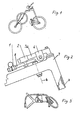
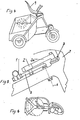
- FIGS. 1 to 3 show an exemplary embodiment of a three-wheeled vehicle with pedal drive; 4 to 6, a light tricycle motor vehicle with a battery-driven electric motor is shown. 1 and 4 each show such vehicles in a perspective view, in FIGS. 2 and 5 the essential parts required for steering are drawn in an enlarged detail, while FIGS. 3 and 6 show plan views of the steering, which should clarify their function and reduction effect.
- the reduction effect of the steering enables and facilitates steering, the effect of which is influenced by the weight of the driver in the pedal-driven vehicle and by the weight of the motor-driven vehicle.
- the reduction effect results from the fact that the guide rod can be rotated by approximately 180 0, while the front wheel fork is rotated thereby at the same time by only about 60 °.
- This ratio and the reduction effect can be selected in the construction of the vehicle by changing the distance between the control column and the steering axis on the one hand, or between the axes of rotation of the handlebar and the connecting bolt on the other.
- the saddle is attached to the reduction rod and the bottom bracket to the front fork. So that the saddle is firmly connected to the front fork via the reduction rod and the control column. This is the prerequisite for the pedal drive acting on the front wheel because the saddle is steered with the front wheel.
- the seat 9 is attached directly to the frame 7.
- the seat with the fork does not have to be rotated because the user's feet do not have a grip on the fork but on the frame.
- the handlebar 1 Grip parts extending obliquely forward and upward, which is advantageous because the handlebar is behind the driver and is rotated around the driver during the steering movement.
Abstract
Description
Die Erfindung betrifft ein Mehrradfahrzeug, nämlich ein Leichtfahrzeug, dessen Vorderrad durch Pedalantrieb angetrieben wird, oder bei dem Motorkraftantrieb auf das Vorderrad oder die Hinterräder einwirkt. Es kann als Fortbewegungsmittel, als Einkaufswagen oder als Transportwagen, zum Beispiel für Zeitungsträger benutzt werden.The invention relates to a multi-wheel vehicle, namely a light vehicle, the front wheel of which is driven by pedal drive, or which acts on the front wheel or the rear wheels in the case of the motor power drive. It can be used as a means of transportation, as a shopping trolley or as a transport trolley, for example for newspaper carriers.
Bei derartigen Fahrzeugen muß das Gleichgewicht gewahrt werden und die Tragfähigkeit muß das Mehrfache der zugelassenen Lasten aufweisen. Die Herstellungskosten sollen dabei möglichst niedrig gehalten werden.In such vehicles, the balance must be maintained and the load capacity must be several times the approved loads. The manufacturing costs should be kept as low as possible.
Auf dem Markt befindliche Leichtfahrzeuge der beschriebenen Art haben insbesondere hinsichtlich des Rahmens die Grundkonstruktion des Fahrrades. Solche Fahrzeuge haben eine Reihe von Teilen, die weit voneinander entfernt liegen und daher durch den Rahmen miteinander verbunden werden müssen. (Radlager, Steuerlager, Tretlager sowie Sattelstütze). Zur Verbindung dieser Teile sind mehrereLight vehicles of the type described on the market have the basic construction of the bicycle, in particular with regard to the frame. Such vehicles have a number of parts that are far apart and therefore must be connected to each other by the frame. (Wheel bearings, steering bearings, bottom bracket and seat post). There are several to connect these parts
hochwertige Leichtrohre und ein verhältnismäßig großer Arbeitsaufwand erforderlich. Die Sitzposition auf einem solchen Fahrzeug muß als unbequem bezeichnet werden.high-quality light pipes and a relatively large amount of work required. The seating position on such a vehicle must be described as uncomfortable.
Aufgabe der Erfindung ist es, den Rahmen eines solchen Fahrzeuges zu vereinfachen und damit das Fahrzeug leichter auszubilden. Benötigtes Material sowie Arbeitsaufwand für die Herstellung des Fahrzeuges sollen verringert werden. Diese Verringerung ist dann möglich, wenn die Konstruktion so ausgebildet wird, daß das Rahmendreieck, welches Steuerlager, Tretlager und Sattelstütze verbindet, in Wegfall kommt.The object of the invention is to simplify the frame of such a vehicle and thus to make the vehicle easier. The material required and the amount of work required to manufacture the vehicle are to be reduced. This reduction is possible when the construction is formed so that the triangle frame, which connects the control bearing, Tret l carrier and seat post, is in elimination.
Ausgehend von einem bekannten Mehrradfahrzeug, dessen Vorderrad in einer Gabel gelagert ist, deren zugehörige Steuersäule ihrerseits einem vorderen Rahmenteil drehbar zugeordnet ist und bei dem im Abstand von der Steuersäule eine parallel zu dieser verlaufende, einen Lenker tragende Lenkachse drehbar gehalten ist, die mit der Steuersäule unter Zwischenschaltung eines Untersetzungsgetriebes in Wirkverbindung steht, wird die oben gekennzeichnete Aufgabe gemäß der Erfindung dadurch gelöst, daß die Lenkachse im vorderen Rahmenteil hinter der Steuersäule angeordnet ist, daß an der Steuersäule eine sich nach hinten erstreckende Untersetzungsstange angerodnet ist und daß die Lenkachse drehfest mit einem sich nach hinten erstreckenden, an seinem hinteren freien Ende den Mittelteil des Lenkers tragenden Ubertragungshebel verbunden ist, der in einer parallel zu der Ebene der Untersetzungsstange verlaufenden Ebene liegt, wobei der Übertragungshebel und die Untersetzungsstange über einen Verbindungsbolzen zwangsläufig miteinander gleitend gekoppelt sind.Starting from a known multi-wheel vehicle, the front wheel of which is mounted in a fork, the associated control column of which is in turn rotatably assigned to a front frame part and in which a steering axle which runs parallel to the steering column and which is parallel to the steering column is rotatably held with the control column with the interposition of a reduction gear in operative connection, the above-identified object is achieved according to the invention in that the steering axis is arranged in the front frame part behind the control column, that a rearwardly extending reduction rod is arranged on the control column and that the steering axis rotatably with a extending rearward, at its rear free end carrying the central part of the handlebar is connected, which run in a parallel to the plane of the reduction rod the level lies, wherein the transmission lever and the reduction rod are necessarily slidably coupled to one another via a connecting bolt.
Wenn eine Ausführung der Erfindung gewählt wird, bei der das Vorderrad mit einem Pedalantrieb versehen ist, wird gemäß einer Weiterbildung der Erfindung an der Untersetzungsstange zwischen der Lenkachse und der Steuersäule eine einen Sattel aufnehmende Klemme angeordnet; der vordere Rahmenteil bildet dann zusammen mit einem ihm zugeordneten hinteren Rahmenteil einen etwa U-förmigen, nach unten offenen Rahmen. In diesem Fall ist das Tretlager des Pedalantriebs außerhalb des Vorderrades und hinter dessen Achse angeordnet.If an embodiment of the invention is selected in which the front wheel is provided with a pedal drive, a clamp receiving a saddle is arranged on the reduction rod between the steering axis and the control column in accordance with a development of the invention; the front frame part then forms an approximately U-shaped, downwardly open frame together with a rear frame part assigned to it. In this case, the bottom bracket of the pedal drive is located outside the front wheel and behind its axle.
Für den Fall, daß für das Fahrzeug ein Motorantrieb vorgesehen ist, wird die Sitzfläche an dem vorderen Rahmenteil festgelegt.In the event that a motor drive is provided for the vehicle, the seat surface is fixed to the front frame part.
In jedem Falle empfiehlt es sich, den Lenker so auszubilden,.daß er schräg nach vorne und oben sich erstreckende Griffteile aufweist.In any case, it is advisable to design the handlebar so that it has grip parts that extend obliquely to the front and upwards.
Gegenüber einer aus der brit. Patentschrift 533 484 bekannten Konstruktion besitzt die erfindungsgemäße Konstruktion eines Mehrradfahrzeuges den Vorteil, daß durch die Anordnung der Lenkachse.hinter der Steuersäule und des Tretlagers hinter der Vorderachse, das Fahrergewicht nach hinten verlegt und dadurch das Fahrverhalten des Fahrzeuges beim Lenken'und Bremsen wesentlich verbessert wird. Weiterhin bestehen die Vorteile, daß die Sitzposition wesentlich verbessert ist und daß der Abstieg für den das Fahrzeug Benutzenden frei geworden ist. Auch die Rahmenkonstruktion ist leichter und einfacher geworden, wodurch sich die Herstellung eines solchen Fahrzeuges verbilligt.Compared to a construction known from British Patent 533,484, the construction according to the invention of a multi-wheel vehicle has the advantage that, by arranging the steering axle behind the steering column and the bottom bracket behind the front axle, the driver's weight is shifted rearward and the driving behavior of the vehicle when steering 'and braking is significantly improved. Furthermore, there are the advantages that the seating position is significantly improved and that the descent for the Vehicle users has become free. The frame construction has also become lighter and simpler, making the manufacture of such a vehicle cheaper.
Zwei Ausführungsbeispiele der Erfindung sind in den Zeichnungen dargestellt.Two embodiments of the invention are shown in the drawings.
In den Fig. 1 bis 3 ist ein Ausführungsbeispiel für ein Dreiradfahrzeug mit Pedalantrieb dargestellt; in den Fig. 4 bis 6 ist ein leichtes Dreiradkraftfahrzeug mit Batterie angetriebenem Elektromotor wiedergegeben. Die Fig. 1 und 4 zeigen jeweils solche Fahrzeuge in perspektifischer Darstellung, in den Fig. 2 und 5 sind in einem vergrößerten Ausschnitt die wesentlichen für die Lenkung erforderlichen Teile gezeichnet, während in den Fig. 3 und 6 Draufsichten auf die Lenkung wiedergegeben sind, wodurch ihre Funktion und Untersetzungswirkung verdeutlich werden soll.1 to 3 show an exemplary embodiment of a three-wheeled vehicle with pedal drive; 4 to 6, a light tricycle motor vehicle with a battery-driven electric motor is shown. 1 and 4 each show such vehicles in a perspective view, in FIGS. 2 and 5 the essential parts required for steering are drawn in an enlarged detail, while FIGS. 3 and 6 show plan views of the steering, which should clarify their function and reduction effect.
Da es sich bei beiden zeichnerisch dargestellten Ausführungsbeispielen hinsichtlich der Konstruktion der Lenkung um die gleichen Teile handelt, sind in den Figuren für gleiche Teile auch gleiche Bezugszeichen verwendet. So erkennt man aus den Darstellungen nach den Fig. 2 und 5 den Rahmen 7, .von welchem nur der vordere Rahmenteil dargestellt ist, die Steuersäule 3 mit der an ihr unter einem rechten Winkel angesetzten Untersetzungsstange 3a, der parallel zur Steuersäule, jedoch hinter ihr angeordneten Lenkachse 6, den Übertragungshebel 8, an dessen freien Ende der Lenker 1 angesetzt ist sowie den Verbindungsbolzen 2, welcher in dem Übertragungshebel 8 drehbar befestigt ist und der gleichzeitig auf der Übersetzungsstange 3a gleiter oder umgekehrt. Auf der Untersetzungsstange ist noch die Klemme 4 zur Befestigung des Sattels angeordnet.Since both exemplary embodiments shown in the drawing are the same parts with regard to the construction of the steering, the same reference numerals are also used in the figures for the same parts. 2 and 5, the
Der Untersetzungseffekt der Lenkung ermöglicht und erleichtert das Lenken, dessen Wirkung beim pedalangetriebenen Fahrzeug vom Gewicht des Fahrers und bei dem mit Motor angetriebenen Fahrzeug vom Motorgewicht beeinflußt wird. Der Untersetzungseffekt ergibt sich dadurch, daß der Lenker um etwa 1800 gedreht werden kann, während die Vorderradgabel dabei gleichzeitig nur um etwa 60° gedreht wird. Dieses Verhältnis sowie der Untersetzungseffekt sind bei der Konstruktion des Fahrzeuges wählbar durch die Abstandsveränderung zwischen der .Steuersäule und der Lenkachse einerseits bzw, zwischen den Drehachsen des Lenkers sowie des Verbindungsbolzens andererseits.The reduction effect of the steering enables and facilitates steering, the effect of which is influenced by the weight of the driver in the pedal-driven vehicle and by the weight of the motor-driven vehicle. The reduction effect results from the fact that the guide rod can be rotated by approximately 180 0, while the front wheel fork is rotated thereby at the same time by only about 60 °. This ratio and the reduction effect can be selected in the construction of the vehicle by changing the distance between the control column and the steering axis on the one hand, or between the axes of rotation of the handlebar and the connecting bolt on the other.
Bei dem in den Fig. 1, 2 und 3 dargestellten pedalangetriebenen Fahrzeug ist der Sattel an der Untersetzungsstange befestigt und das Tretlager an der Vorderradgabel. Damit wird der Sattel über die Untersetzungsstange und die Steuersäule mit der Vorderradgabel fest verbunden. Das ist die Voraussetzung für den auf das Vorderrad einwirkenden Pedalantrieb, weil der Sattel mit dem Vorderrad mitgelenkt wird.In the pedal-powered vehicle shown in Figs. 1, 2 and 3, the saddle is attached to the reduction rod and the bottom bracket to the front fork. So that the saddle is firmly connected to the front fork via the reduction rod and the control column. This is the prerequisite for the pedal drive acting on the front wheel because the saddle is steered with the front wheel.
Bei dem in den Fig. 4 bis 6 dargestellten Fahrzeug mit Motorantrieb wird die Sitzfläche 9 direkt am Rahmen 7 befestigt. In diesem Fall braucht die Sitzfläche mit der Gabel nicht mitgedreht zu werden, weil die Füße des Benutzers nicht an der Gabel, sondern am Rahmen einen Halt haben.In the vehicle with motor drive shown in FIGS. 4 to 6, the seat 9 is attached directly to the
In beiden Ausführungsbeispielen weist der Lenker 1 . schräg nach vorne und oben sich erstreckende Griffteile auf, was deshalb von Vorteil ist, weil ja der Lenker sich hinter dem Fahrer befindet und während der Lenkbewegung um den Fahrer gedreht wird.In both exemplary embodiments, the
Claims (5)
Applications Claiming Priority (2)
| Application Number | Priority Date | Filing Date | Title |
|---|---|---|---|
| DE19813100185 DE3100185C2 (en) | 1981-01-07 | 1981-01-07 | Light vehicle |
| DE3100185 | 1981-01-07 |
Publications (2)
| Publication Number | Publication Date |
|---|---|
| EP0055837A1 true EP0055837A1 (en) | 1982-07-14 |
| EP0055837B1 EP0055837B1 (en) | 1984-10-10 |
Family
ID=6122248
Family Applications (1)
| Application Number | Title | Priority Date | Filing Date |
|---|---|---|---|
| EP19810110492 Expired EP0055837B1 (en) | 1981-01-07 | 1981-12-16 | Light vehicle |
Country Status (5)
| Country | Link |
|---|---|
| EP (1) | EP0055837B1 (en) |
| JP (1) | JPS588479A (en) |
| DE (1) | DE3100185C2 (en) |
| ES (1) | ES8301798A1 (en) |
| IN (1) | IN154979B (en) |
Cited By (3)
| Publication number | Priority date | Publication date | Assignee | Title |
|---|---|---|---|---|
| FR2538770A1 (en) * | 1983-01-05 | 1984-07-06 | Teillaud Albert | Bicycle handlebars with adjustable height. |
| NL9400257A (en) * | 1994-02-21 | 1995-10-02 | Bastiaan Andreas D Herripon | Bicycle |
| EP1364866A1 (en) * | 2002-05-23 | 2003-11-26 | Tseng-Hsien Chen | Strength-saving steering mechanism for bicycles |
Families Citing this family (2)
| Publication number | Priority date | Publication date | Assignee | Title |
|---|---|---|---|---|
| US9114843B2 (en) | 2008-07-17 | 2015-08-25 | Projectgarlic Limited | Collapsible cycle |
| CN103496417B (en) * | 2013-09-25 | 2016-08-17 | 广东顺德卡宾新能源技术有限公司 | A kind of forerunner's tricycle |
Citations (8)
| Publication number | Priority date | Publication date | Assignee | Title |
|---|---|---|---|---|
| DE48353C (en) * | PH. HEINS in Rostock i. M., Neuer Markt 32 | steering device on three-wheeled bicycles | ||
| DE40201C (en) * | HAASE & STAMM in Berlin S., Kommandantenstr. 48 | Three-wheeled bicycle with rear wheel | ||
| FR857529A (en) * | 1939-03-30 | 1940-09-17 | Improvements to cycles in which the cyclist is lying down | |
| CH234015A (en) * | 1938-11-28 | 1944-08-31 | Anonyme Cie Croix Societe | Vehicle operated by pedals. |
| FR974108A (en) * | 1941-12-17 | 1951-02-19 | Front-wheel drive bicycle or motorcycle | |
| DE822208C (en) * | 1950-05-09 | 1951-11-22 | Erich Mueller | tricycle |
| GB729782A (en) * | 1952-12-01 | 1955-05-11 | Stanley Engineering Company Lt | Improvements in or relating to steering arrangements for vehicles |
| DE3021135A1 (en) * | 1980-06-04 | 1981-12-10 | Hartmut 4800 Bielefeld Wagner | Skid free motor vehicle - has independently height adjustable rear wheels and single steerable front wheel |
Family Cites Families (1)
| Publication number | Priority date | Publication date | Assignee | Title |
|---|---|---|---|---|
| GB533484A (en) * | 1939-11-10 | 1941-02-13 | Cie Croix | Improvements in or relating to carrier tricycles and like three wheel vehicles |
-
1981
- 1981-01-07 DE DE19813100185 patent/DE3100185C2/en not_active Expired
- 1981-12-16 EP EP19810110492 patent/EP0055837B1/en not_active Expired
- 1981-12-29 IN IN1472/CAL/81A patent/IN154979B/en unknown
-
1982
- 1982-01-07 JP JP57000658A patent/JPS588479A/en active Pending
- 1982-01-07 ES ES508576A patent/ES8301798A1/en not_active Expired
Patent Citations (8)
| Publication number | Priority date | Publication date | Assignee | Title |
|---|---|---|---|---|
| DE48353C (en) * | PH. HEINS in Rostock i. M., Neuer Markt 32 | steering device on three-wheeled bicycles | ||
| DE40201C (en) * | HAASE & STAMM in Berlin S., Kommandantenstr. 48 | Three-wheeled bicycle with rear wheel | ||
| CH234015A (en) * | 1938-11-28 | 1944-08-31 | Anonyme Cie Croix Societe | Vehicle operated by pedals. |
| FR857529A (en) * | 1939-03-30 | 1940-09-17 | Improvements to cycles in which the cyclist is lying down | |
| FR974108A (en) * | 1941-12-17 | 1951-02-19 | Front-wheel drive bicycle or motorcycle | |
| DE822208C (en) * | 1950-05-09 | 1951-11-22 | Erich Mueller | tricycle |
| GB729782A (en) * | 1952-12-01 | 1955-05-11 | Stanley Engineering Company Lt | Improvements in or relating to steering arrangements for vehicles |
| DE3021135A1 (en) * | 1980-06-04 | 1981-12-10 | Hartmut 4800 Bielefeld Wagner | Skid free motor vehicle - has independently height adjustable rear wheels and single steerable front wheel |
Cited By (3)
| Publication number | Priority date | Publication date | Assignee | Title |
|---|---|---|---|---|
| FR2538770A1 (en) * | 1983-01-05 | 1984-07-06 | Teillaud Albert | Bicycle handlebars with adjustable height. |
| NL9400257A (en) * | 1994-02-21 | 1995-10-02 | Bastiaan Andreas D Herripon | Bicycle |
| EP1364866A1 (en) * | 2002-05-23 | 2003-11-26 | Tseng-Hsien Chen | Strength-saving steering mechanism for bicycles |
Also Published As
| Publication number | Publication date |
|---|---|
| ES508576A0 (en) | 1982-12-16 |
| DE3100185C2 (en) | 1983-12-15 |
| EP0055837B1 (en) | 1984-10-10 |
| ES8301798A1 (en) | 1982-12-16 |
| IN154979B (en) | 1984-12-22 |
| JPS588479A (en) | 1983-01-18 |
| DE3100185A1 (en) | 1982-08-05 |
Similar Documents
| Publication | Publication Date | Title |
|---|---|---|
| DE60303842T2 (en) | Folding bicycle | |
| DE19848602B4 (en) | Bicycle powered by power | |
| EP1993899A1 (en) | Vehicle which can tilt in bends, in particular three-wheeled vehicle | |
| WO2016023689A1 (en) | Motor vehicle | |
| DE102013011496A1 (en) | Muscle-powered multi-wheeled vehicle | |
| DE2656966A1 (en) | SELF-DRIVING COMPACT VEHICLE | |
| EP0055837A1 (en) | Light vehicle | |
| DE4124926C2 (en) | tricycle | |
| DE3009287A1 (en) | BIKE FROM PRE-MADE BICYCLE COMPONENTS | |
| DE10036997A1 (en) | Multi-functional vehicle as pushchair or child's bicycle has bearing box for attachment of rear wheel support arms and with pivot bearing with vertical pivot for mounting of V-form symmetrically formed main support component of frame | |
| DE10249616B4 (en) | Tricycle with curve slope | |
| DE19625382A1 (en) | Multi=purpose vehicle | |
| AT524526B1 (en) | vehicle | |
| DE102021101712A1 (en) | cargo bike | |
| DE202020104101U1 (en) | Steerable vehicle | |
| DE19513649A1 (en) | Three-wheeled vehicle for use like bicycle or motorcycle | |
| DE102016004528A1 (en) | Bicycle with foldable trained frame structure | |
| DE102019123643A1 (en) | Multifunctional vehicle | |
| DE19736266A1 (en) | Prone bicycle with front wheel propulsion and front wheel steering | |
| DE19633061C1 (en) | Scooter with step board | |
| EP3514044B1 (en) | Vehicle | |
| DE10032105A1 (en) | Foldable bicycle with conventional front fork and pivot axis for rear frame section located skewed in horizontal plane below bottom bracket | |
| DE10105743C1 (en) | Main frame and sub frames for three-wheeled vehicle has two front wheels mounted on motorcycle front forks, two seats side-by-side and single rear wheel | |
| DD284200A5 (en) | TWOWZW. TRICYCLE | |
| DE1748493U (en) | THREE-WHEELED SELF-VEHICLE, ESPECIALLY FOR CHILDREN. |
Legal Events
| Date | Code | Title | Description |
|---|---|---|---|
| PUAI | Public reference made under article 153(3) epc to a published international application that has entered the european phase |
Free format text: ORIGINAL CODE: 0009012 |
|
| AK | Designated contracting states |
Designated state(s): BE CH FR GB IT LI NL |
|
| 17P | Request for examination filed |
Effective date: 19820708 |
|
| ITF | It: translation for a ep patent filed |
Owner name: OBEROSLER LUDWIG |
|
| GRAA | (expected) grant |
Free format text: ORIGINAL CODE: 0009210 |
|
| AK | Designated contracting states |
Designated state(s): BE CH FR GB IT LI NL |
|
| PGFP | Annual fee paid to national office [announced via postgrant information from national office to epo] |
Ref country code: FR Payment date: 19841207 Year of fee payment: 4 |
|
| PGFP | Annual fee paid to national office [announced via postgrant information from national office to epo] |
Ref country code: CH Payment date: 19841211 Year of fee payment: 4 |
|
| PGFP | Annual fee paid to national office [announced via postgrant information from national office to epo] |
Ref country code: NL Payment date: 19841212 Year of fee payment: 4 |
|
| ET | Fr: translation filed | ||
| PGFP | Annual fee paid to national office [announced via postgrant information from national office to epo] |
Ref country code: BE Payment date: 19841231 Year of fee payment: 4 |
|
| PLBE | No opposition filed within time limit |
Free format text: ORIGINAL CODE: 0009261 |
|
| STAA | Information on the status of an ep patent application or granted ep patent |
Free format text: STATUS: NO OPPOSITION FILED WITHIN TIME LIMIT |
|
| 26N | No opposition filed | ||
| PG25 | Lapsed in a contracting state [announced via postgrant information from national office to epo] |
Ref country code: LI Effective date: 19851231 Ref country code: CH Effective date: 19851231 Ref country code: BE Effective date: 19851231 |
|
| BERE | Be: lapsed |
Owner name: LUCIC IVO Effective date: 19851231 |
|
| PG25 | Lapsed in a contracting state [announced via postgrant information from national office to epo] |
Ref country code: NL Effective date: 19860701 |
|
| GBPC | Gb: european patent ceased through non-payment of renewal fee | ||
| NLV4 | Nl: lapsed or anulled due to non-payment of the annual fee | ||
| PG25 | Lapsed in a contracting state [announced via postgrant information from national office to epo] |
Ref country code: FR Free format text: LAPSE BECAUSE OF NON-PAYMENT OF DUE FEES Effective date: 19860829 |
|
| REG | Reference to a national code |
Ref country code: CH Ref legal event code: PL |
|
| REG | Reference to a national code |
Ref country code: FR Ref legal event code: ST |
|
| PG25 | Lapsed in a contracting state [announced via postgrant information from national office to epo] |
Ref country code: GB Effective date: 19881121 |