EP0055463B1 - Heating device - Google Patents
Heating device Download PDFInfo
- Publication number
- EP0055463B1 EP0055463B1 EP81110698A EP81110698A EP0055463B1 EP 0055463 B1 EP0055463 B1 EP 0055463B1 EP 81110698 A EP81110698 A EP 81110698A EP 81110698 A EP81110698 A EP 81110698A EP 0055463 B1 EP0055463 B1 EP 0055463B1
- Authority
- EP
- European Patent Office
- Prior art keywords
- reflecting mirror
- optical guide
- heating device
- guide member
- heated
- Prior art date
- Legal status (The legal status is an assumption and is not a legal conclusion. Google has not performed a legal analysis and makes no representation as to the accuracy of the status listed.)
- Expired
Links
Images

Classifications
-
- B—PERFORMING OPERATIONS; TRANSPORTING
- B23—MACHINE TOOLS; METAL-WORKING NOT OTHERWISE PROVIDED FOR
- B23K—SOLDERING OR UNSOLDERING; WELDING; CLADDING OR PLATING BY SOLDERING OR WELDING; CUTTING BY APPLYING HEAT LOCALLY, e.g. FLAME CUTTING; WORKING BY LASER BEAM
- B23K26/00—Working by laser beam, e.g. welding, cutting or boring
- B23K26/08—Devices involving relative movement between laser beam and workpiece
- B23K26/0823—Devices involving rotation of the workpiece
-
- B—PERFORMING OPERATIONS; TRANSPORTING
- B23—MACHINE TOOLS; METAL-WORKING NOT OTHERWISE PROVIDED FOR
- B23K—SOLDERING OR UNSOLDERING; WELDING; CLADDING OR PLATING BY SOLDERING OR WELDING; CUTTING BY APPLYING HEAT LOCALLY, e.g. FLAME CUTTING; WORKING BY LASER BEAM
- B23K26/00—Working by laser beam, e.g. welding, cutting or boring
- B23K26/08—Devices involving relative movement between laser beam and workpiece
- B23K26/082—Scanning systems, i.e. devices involving movement of the laser beam relative to the laser head
Definitions
- the heated region is reciprocally scanned by the laser beam for heating
- one method is conventionally adopted in which a laser beam is radiated on an object to be heated through a reflecting mirror, and the reflecting mirror is vibrated at a constant amplitude and frequency so that the laser beam which is incident moves reciprocally.
- Japanese Laid-Open Patent Application 54-101576 proposes that the power of the laser beam be changed in response to the displacement of the reflecting mirror.
- changes in the power of the laser beam may not easily be accomplished and this device entails higher cost.
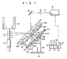
- the heating device 14 comprises a laser oscillator or laser beam radiation device 15, first and second reflecting mirrors 16 and 17 which guide a laser beam P emitted from the laser oscillator 15 to the region 13, a drive mechanism 19 which pivotally vibrates the reflecting mirror 17 in the direction indicated by arrow 18, a free vibration force biasing mechanism 20 which biases the reflecting mirror 17 to assure free pivotal vibration, and a controller 21 which controls the operation timing and period of laser beam emission from the laser oscillator 15 and the operation timing and period of the drive mechanism 19.
- a magnetic body comprises a pair of iron pieces 35a and 35b which are mounted to extend at both end of the reflecting mirror support plate 34 whose center is defined by the pin 33.
- the upper end of the support member 32 extends along the reflecting mirror support plate 34.
- a pair of electromagnets 36a and 36b which are spaced apart at a predetermined distance from the iron pieces 35a and 35b and which oppose the iron pieces 35a and 35b are mounted to the upper end of the reflecting mirror support plate 34.
- the electromagnets 36a and 36b are constituted by iron cores around the peripheries of which are respectively wound coils. When a DC current is supplied to the electromagnets 36a and 36b, the electromagnets 36a and 36b are energized to attract the iron pieces 35a and 35b.
- the free vibration force biasing mechanism 20 has a rod 37 which extends perpendicularly to the reflecting mirror support plate 34 at the center of the lower surface thereof.
- a pair of stationary pins 38a and 38b extend in opposite directions at the lower section of the rod 37.
- the stationary pins 38a and 38b are inserted in one end each of a pair of compression coil springs 39a and 39b which extend in the direction perpendicular to the rod 37 and the pin 33, so that the stationary pins 38a and 38b respectively support the compression coil springs 39a and 39b.
- a pair of extended sections 40a and 40b are disposed, to oppose each other, and the rod 37 is located at the center between the extended sections 40a and 40b on one side of the support member 32.
- reference numeral 60 denotes a pincher which flattens the heated part of the quartz tube 11 by clamping it from both sides.
- heating is performed so that a uniform temperature distribution is established throughout a length L in the axial direction of the prospective heating region 13; the distance described above is set so that a half-amplitude D of the laser beam P in the prospective heating region 13 satisfies the condition L:5 2D.
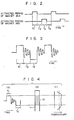
- the timer switch 52 is set to a predetermined time, while the biasing periods of the electromagnets 36a and 36b and the nonbiasing periods thereof are set by the timer switches 53, 54 and 55.
- a biasing period T1 of one electromagnet 36a, a biasing period T2 of the other electromagnet 36b, and a nonbiasing period T3 must have a ratio of 1:1:1.
- the second reflecting mirror 17 stops at the maximum tilted position for a period in which the iron pieces 35a and 35b are attracted to the corresponding electromagnets, for example, a period of about 1/10 second, as shown in Fig. 3.
- the movement of the second reflecting mirror 17 is damped by the biasing force of the compression springs 39a and 39b when the iron pieces are attracted.
- the second reflecting mirror 17 stops for the period in which the electromagnet is energized when the laser beam P is radiated on the end portion of the prospective heating region 13. For the nonbiasing period, the movement of the second reflecting mirror 17 is damped when the laser beam P is radiated on portions other than the end portion of the prospective heating region 13.
- the vibration mode of the second reflecting mirror 17 is controlled while maintaining a constant output of the laser oscillator 15, so that the predetermined region of the object to be heated may be heated with a constant temperature distribution, making the cost of the overall device low.
- the periods T1, T2 and T3 are substantially the same to accomplish the uniform temperature distribution of the prospective heating region.
- these periods may be adjusted to accomplish various temperature distributions as needed.
- the temperature distribution may be varied by changing the vibration characteristics such as the damping frequency and the damping constant of the compressing springs since they influence the temperature distribution.
- the vibration characteristics may be easily changed by changing the pressing force of the compressing springs with the adjust screws or by adding a damper.
- part of the waveform of the vibration of the reflecting mirror is determined as an accurate rectangular waveform.
- other waveforms in which the amplitude does not change for a predetermined period such as a trapezoidal waveform, may be used.
- the reflecting mirror is preferably cooled.
- cooling means such as a water cooling jacket may be mounted to the reflecting mirror support plate to accomplish this purpose.
- the device according to the embodiment as described above is used for the softening-pinching of the quartz tube.
- this heating device may also be used for other heating treatments such as a heat treatment of a metal.
- the object to be heated rotates.
- the reflecting mirror may rotate around the object to be heated while the object is kept stationary.
- the reflecting mirror is vibrated by a combination of the assembly of the electromagnet and the iron core, and the compression springs.
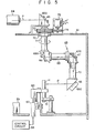
- the reflecting mirror may be vibrated by another means such as a cam, an example of which will be described with reference to Figs. 5 to 7.
- the laser beam radiation system 63 has a laser oscillator 64 which is disposed outside the case 61, and a first reflecting mirror 65 which is disposed above the upper wall of the case 61, which reflects the laser beam P at right angles, and which is mounted to first support body 67a to guide the laser beam P into the case 61 vertically, Further, within the case 61 are mounted together so as to be freely movable: a second reflecting mirror 66 which is mounted to a second support body 66a so as to guide the laser beam P from the first reflecting mirror 65 horizontally by reflecting the laser beam P at right angles; a third reflecting mirror 67 which is mounted to a third support body 67a so as to guide the laser beam P from the second reflecting mirror 65 vertically and downwardly by reflecting the laser beam P at right angles; and a fourth reflecting mirror 68 which is mounted to a fourth support body 68a so as to guide the laser beam P horizontally to the quartz tube 11 by reflecting the laser beam P at right angles.
- the first reflecting mirror 65 and the second reflecting mirror 66 are located above the quartz tube 11 so that the optical axes thereof are coaxial with the central axis of the quartz tube 11.
- the first support body 65a is stationary relative to the upper wall of the case 61.
- the second support body 66a is rotatably supported from the upper wall of the case 61 and is mounted to the lower end of a vertical cylindrical body 71, the upper end of which extends through the upper wall.
- the rotating shaft of the cylindrical body 71 coincides with the optical axis of the first reflecting mirror 65.
- a large gear 73 is mounted to be coaxial with the rotating shaft of the cylindrical body 71, the end of which extends from the upper wall of the base 61.
- the resultant reduction gear train is driven by the motor 75 to rotate in the direction indicated by the arrow, and at the same time the second reflecting mirror 66 above the quartz tube 11 rotates in the direction indicated by the arrow about the central axis of the quartz tube 11 through the cylindrical body 71.
- reference numeral 59 denotes a control unit which controls the laser oscillator 64, the motor 75, the hydraulic controller 58 and the drive mechanism which is disposed within the fourth support body 68a and which vibrates the fourth reflecting mirror 68 to be described later.
- the fourth reflecting mirror 68 is constituted by a concave mirror as shown in Fig. 6, and focuses . the laser beam P on the heated region.
- the concave mirror 68 is mounted at the central upper surface of a reflecting mirror support plate 80 in which water cooling jackets 81 are formed.
- the reflecting mirror support plate 80 is mounted to the fourth support body 68a so as to be pivotal about a horizontal pin 82 at the center of the cross section of the reflecting mirror support plate 80.
- a compression coil spring 82 is mounted between the fourth support body 68a and the lower surface of the reflecting mirror support plate 80 in the vicinity of one end so that the compression coil spring 82 pivotally biases the reflecting mirror supporting plate 80 in the direction indicated by the arrow.
- a driven element 83 is mounted to the lower surface of the reflecting mirror support plate 80 in the vicinity of the other end, and engages with a cam 84 which is rotatably supported by the fourth support body 68a.
- the cam 84 is rotated by a motor 85, the reflecting mirror support plate 80 is free to vibrate through the driven element 83.
- the cam surface of the cam 84 is set to vibrate the reflecting mirror support plate 80 and simultaneously vibrate the fourth reflecting mirror 68 with a vibration waveform as shown in Fig. 7.
- the fourth reflecting mirror 68 stops at a position when the fourth reflecting mirror 68 pivots a maximum angle in the direction indicated by the arrow for the period T1.
- the fourth reflecting mirror 68 pivots a maximum angle in a direction opposite to the direction indicated by the arrow. At this position, the fourth reflecting mirror 68 stops for the nonbiasing period T3. During the period T2 in which the fourth reflecting mirror 68 pivots, the fourth reflecting mirror 68 pivots at a constant speed except for a temporary stop in the middle of the rotation.
- the ratio of periods T1, T2 and T3 is determined to be substantially equal. Even when the period T2 is set to be shorter than the periods T1 and T3, the heated region is entirely heated substantially uniformly, or the central portion may be heated slightly less than the other portions.
- the fourth reflecting mirror 68 rotates around the quartz tube 11 with the vibration pattern as shown in Fig. 7, the laser beam P transmitted to the fourth reflecting mirror 68 is radiated on the periphery of the quartz tube 11, by which the entire predetermined region is heated substantially uniformly.
Applications Claiming Priority (2)
| Application Number | Priority Date | Filing Date | Title |
|---|---|---|---|
| JP185837/80 | 1980-12-26 | ||
| JP55185837A JPS5952037B2 (ja) | 1980-12-26 | 1980-12-26 | レ−ザ加工装置 |
Publications (3)
| Publication Number | Publication Date |
|---|---|
| EP0055463A2 EP0055463A2 (en) | 1982-07-07 |
| EP0055463A3 EP0055463A3 (en) | 1982-10-20 |
| EP0055463B1 true EP0055463B1 (en) | 1986-03-19 |
Family
ID=16177739
Family Applications (1)
| Application Number | Title | Priority Date | Filing Date |
|---|---|---|---|
| EP81110698A Expired EP0055463B1 (en) | 1980-12-26 | 1981-12-22 | Heating device |
Country Status (4)
| Country | Link |
|---|---|
| US (1) | US4429210A (ja) |
| EP (1) | EP0055463B1 (ja) |
| JP (1) | JPS5952037B2 (ja) |
| DE (1) | DE3174157D1 (ja) |
Families Citing this family (17)
| Publication number | Priority date | Publication date | Assignee | Title |
|---|---|---|---|---|
| FR2577052B1 (fr) * | 1985-02-05 | 1988-09-09 | Bertin & Cie | Procede et dispositif de deplacement du point d'impact d'un faisceau laser sur une piece |
| FR2583325B1 (fr) * | 1985-06-17 | 1989-01-20 | Inst Mash Im | Dispositif de balayage pour une installation a laser technologique |
| CA1284823C (en) * | 1985-10-22 | 1991-06-11 | Kenneth K. York | Systems and methods for creating rounded work surfaces by photoablation |
| SU1430931A1 (ru) * | 1985-11-04 | 1988-10-15 | Институт Машиноведения Им.А.А.Благонравова | Сканатор дл лазерных технологических установок |
| US4678422A (en) * | 1985-11-12 | 1987-07-07 | York Kenneth K | Systems and methods for precise, accurate formation of products by photoablation |
| FR2622710A1 (fr) * | 1987-10-30 | 1989-05-05 | Sciaky Sa | Dispositif de commande en pivotement d'un outil et, notamment d'un miroir de reflexion d'un faisceau laser |
| CA1325041C (en) * | 1988-08-15 | 1993-12-07 | Michael Peter Gaukroger | Cutting using high energy radiation |
| DE3850256T2 (de) * | 1988-11-18 | 1994-10-13 | Toyoda Machine Works Ltd | Verfahren und Vorrichtung zur Behandlung einer bearbeiteten Fläche eines Werkstücks. |
| FR2691589B1 (fr) * | 1992-05-20 | 1995-05-05 | Seram | Dispositif générateur d'oscillations pour faisceaux laser de forte puissance. |
| JP3060813B2 (ja) * | 1993-12-28 | 2000-07-10 | トヨタ自動車株式会社 | レーザ加工装置 |
| DE4430220C2 (de) * | 1994-08-25 | 1998-01-22 | Fraunhofer Ges Forschung | Verfahren zur Steuerung der Laserstrahlintensitätsverteilung auf der Oberfläche zu bearbeitender Bauteile |
| US6034803A (en) * | 1997-04-30 | 2000-03-07 | K2 T, Inc. | Method and apparatus for directing energy based range detection sensor |
| EP2133715A1 (de) * | 2008-06-11 | 2009-12-16 | Pantec Biosolutions AG | Vorrichtung und Verfahren zum Ablenken einer elektromagnetischen Strahlung, insbesondere eines Laserstrahls |
| EP2304481A2 (en) | 2008-06-11 | 2011-04-06 | Pantec Biosolutions AG | Apparatus and method for the deflection of electromagnetic radiation, in particular of a laser beam |
| RU2487702C2 (ru) * | 2009-05-12 | 2013-07-20 | Республиканское Унитарное производственное предприятие "Белмедпрепараты" | Лекарственное средство для лечения туберкулеза |
| AT513467B1 (de) * | 2012-09-26 | 2014-07-15 | Trumpf Maschinen Austria Gmbh | Verfahren zum Biegen eines Werkstücks |
| RU2618287C2 (ru) * | 2015-08-04 | 2017-05-03 | Федеральное государственное бюджетное образовательное учреждение высшего образования "Казанский национальный исследовательский технический университет им. А.Н. Туполева - КАИ" (КНИТУ-КАИ) | Способ лазерной обработки изделия (варианты) и устройство для его осуществления (варианты) |
Family Cites Families (4)
| Publication number | Priority date | Publication date | Assignee | Title |
|---|---|---|---|---|
| CH468083A (de) * | 1968-02-09 | 1969-01-31 | Siemens Ag | Verfahren zum formändernden Bearbeiten eines kristallinen Körpers aus Halbleitermaterial, insbesondere eines Siliziumeinkristalls |
| US4107528A (en) * | 1972-06-13 | 1978-08-15 | Daniel Silverman | Method and apparatus for transferring a pattern on an overlying web by laser burning onto an underlying web |
| US3848104A (en) * | 1973-04-09 | 1974-11-12 | Avco Everett Res Lab Inc | Apparatus for heat treating a surface |
| US4063064A (en) * | 1976-02-23 | 1977-12-13 | Coherent Radiation | Apparatus for tracking moving workpiece by a laser beam |
-
1980
- 1980-12-26 JP JP55185837A patent/JPS5952037B2/ja not_active Expired
-
1981
- 1981-12-21 US US06/332,829 patent/US4429210A/en not_active Expired - Fee Related
- 1981-12-22 DE DE8181110698T patent/DE3174157D1/de not_active Expired
- 1981-12-22 EP EP81110698A patent/EP0055463B1/en not_active Expired
Also Published As
| Publication number | Publication date |
|---|---|
| DE3174157D1 (en) | 1986-04-24 |
| EP0055463A3 (en) | 1982-10-20 |
| US4429210A (en) | 1984-01-31 |
| JPS5952037B2 (ja) | 1984-12-17 |
| EP0055463A2 (en) | 1982-07-07 |
| JPS57109589A (en) | 1982-07-08 |
Similar Documents
| Publication | Publication Date | Title |
|---|---|---|
| EP0055463B1 (en) | Heating device | |
| KR0165906B1 (ko) | 레이저 빔 진동장치 및 그것을 구비한 레이저 가공장치 | |
| US6640604B2 (en) | Laser bending method and apparatus for bending a work piece in normal and reverse directions | |
| US3848104A (en) | Apparatus for heat treating a surface | |
| KR100657196B1 (ko) | 스크라이브 라인 형성장치 및 스크라이브 라인 형성방법 | |
| JP4988202B2 (ja) | 工作物の支持及び熱処理の方法とシステム | |
| JP2021506593A (ja) | 電磁波ビームを整形するための光学装置およびその使用、ビーム処理装置およびその使用、ならびにビーム処理方法 | |
| US4856858A (en) | Optical scanner | |
| KR100403586B1 (ko) | 광픽업 장치 및 그 조립방법 | |
| JP3456424B2 (ja) | レーザ溶接方法及びレーザ溶接装置 | |
| US5034953A (en) | Laser device capable of making a temperature distribution uniform in a slab-shaped laser medium | |
| JPH04501583A (ja) | アモルファスセラミック製品または金属合金を製造する装置 | |
| JP2000309056A (ja) | 熱可塑性物突起を変形するための方法及び装置 | |
| KR100650922B1 (ko) | 레이저 용접장치 | |
| US6198066B1 (en) | Method and apparatus for radiated beam marking of a golf club part and such part | |
| JP3425162B2 (ja) | 熱変形素子の熱変形に伴う衝撃力を利用した微小移動装置 | |
| EP0688062A2 (en) | Adjustable fresnel zone plate | |
| EP0427441A2 (en) | Objective lens actuator | |
| KR100507837B1 (ko) | 내로우 갭 용접을 위한 전자석 요동토치 | |
| CN117139825A (zh) | 一种激光加工装置 | |
| JPH06292986A (ja) | レーザ加工装置の制御方法 | |
| KR100347767B1 (ko) | 레이저 발진기의 개구제어장치 | |
| LT7012B (lt) | Lakštinių detalių palaipsninio formavimo prietaisas | |
| JP2003037020A (ja) | 電子部品形成体の加工装置 | |
| US20020170318A1 (en) | Brief summary of the invention |
Legal Events
| Date | Code | Title | Description |
|---|---|---|---|
| PUAI | Public reference made under article 153(3) epc to a published international application that has entered the european phase |
Free format text: ORIGINAL CODE: 0009012 |
|
| AK | Designated contracting states |
Designated state(s): DE GB NL |
|
| PUAL | Search report despatched |
Free format text: ORIGINAL CODE: 0009013 |
|
| AK | Designated contracting states |
Designated state(s): DE GB NL |
|
| 17P | Request for examination filed |
Effective date: 19830411 |
|
| RAP1 | Party data changed (applicant data changed or rights of an application transferred) |
Owner name: KABUSHIKI KAISHA TOSHIBA |
|
| GRAA | (expected) grant |
Free format text: ORIGINAL CODE: 0009210 |
|
| AK | Designated contracting states |
Kind code of ref document: B1 Designated state(s): DE GB NL |
|
| REF | Corresponds to: |
Ref document number: 3174157 Country of ref document: DE Date of ref document: 19860424 |
|
| PLBE | No opposition filed within time limit |
Free format text: ORIGINAL CODE: 0009261 |
|
| STAA | Information on the status of an ep patent application or granted ep patent |
Free format text: STATUS: NO OPPOSITION FILED WITHIN TIME LIMIT |
|
| 26N | No opposition filed | ||
| PGFP | Annual fee paid to national office [announced via postgrant information from national office to epo] |
Ref country code: NL Payment date: 19871231 Year of fee payment: 7 |
|
| PGFP | Annual fee paid to national office [announced via postgrant information from national office to epo] |
Ref country code: DE Payment date: 19890131 Year of fee payment: 8 |
|
| PG25 | Lapsed in a contracting state [announced via postgrant information from national office to epo] |
Ref country code: GB Effective date: 19891222 |
|
| PG25 | Lapsed in a contracting state [announced via postgrant information from national office to epo] |
Ref country code: NL Effective date: 19900701 |
|
| NLV4 | Nl: lapsed or anulled due to non-payment of the annual fee | ||
| GBPC | Gb: european patent ceased through non-payment of renewal fee | ||
| PG25 | Lapsed in a contracting state [announced via postgrant information from national office to epo] |
Ref country code: DE Effective date: 19900901 |