EP0055463B1 - Heating device - Google Patents
Heating device Download PDFInfo
- Publication number
- EP0055463B1 EP0055463B1 EP81110698A EP81110698A EP0055463B1 EP 0055463 B1 EP0055463 B1 EP 0055463B1 EP 81110698 A EP81110698 A EP 81110698A EP 81110698 A EP81110698 A EP 81110698A EP 0055463 B1 EP0055463 B1 EP 0055463B1
- Authority
- EP
- European Patent Office
- Prior art keywords
- reflecting mirror
- optical guide
- heating device
- guide member
- heated
- Prior art date
- Legal status (The legal status is an assumption and is not a legal conclusion. Google has not performed a legal analysis and makes no representation as to the accuracy of the status listed.)
- Expired
Links
- 238000010438 heat treatment Methods 0.000 title claims description 53
- 230000003287 optical effect Effects 0.000 claims description 17
- 238000013016 damping Methods 0.000 claims description 4
- 239000010453 quartz Substances 0.000 description 26
- VYPSYNLAJGMNEJ-UHFFFAOYSA-N silicon dioxide Inorganic materials O=[Si]=O VYPSYNLAJGMNEJ-UHFFFAOYSA-N 0.000 description 26
- XEEYBQQBJWHFJM-UHFFFAOYSA-N Iron Chemical compound [Fe] XEEYBQQBJWHFJM-UHFFFAOYSA-N 0.000 description 20
- 238000009826 distribution Methods 0.000 description 12
- 230000007246 mechanism Effects 0.000 description 11
- 230000006835 compression Effects 0.000 description 9
- 238000007906 compression Methods 0.000 description 9
- 229910052742 iron Inorganic materials 0.000 description 9
- 238000000034 method Methods 0.000 description 4
- 238000001816 cooling Methods 0.000 description 3
- 230000005855 radiation Effects 0.000 description 3
- 239000002184 metal Substances 0.000 description 2
- 229910052751 metal Inorganic materials 0.000 description 2
- 230000010355 oscillation Effects 0.000 description 2
- 238000003825 pressing Methods 0.000 description 2
- 230000008569 process Effects 0.000 description 2
- 230000004044 response Effects 0.000 description 2
- XLYOFNOQVPJJNP-UHFFFAOYSA-N water Substances O XLYOFNOQVPJJNP-UHFFFAOYSA-N 0.000 description 2
- 230000008859 change Effects 0.000 description 1
- 238000006073 displacement reaction Methods 0.000 description 1
- 239000011521 glass Substances 0.000 description 1
- 238000004519 manufacturing process Methods 0.000 description 1
- 238000002360 preparation method Methods 0.000 description 1
- 230000009467 reduction Effects 0.000 description 1
- 238000011282 treatment Methods 0.000 description 1
Images

Classifications
-
- B—PERFORMING OPERATIONS; TRANSPORTING
- B23—MACHINE TOOLS; METAL-WORKING NOT OTHERWISE PROVIDED FOR
- B23K—SOLDERING OR UNSOLDERING; WELDING; CLADDING OR PLATING BY SOLDERING OR WELDING; CUTTING BY APPLYING HEAT LOCALLY, e.g. FLAME CUTTING; WORKING BY LASER BEAM
- B23K26/00—Working by laser beam, e.g. welding, cutting or boring
- B23K26/08—Devices involving relative movement between laser beam and workpiece
- B23K26/0823—Devices involving rotation of the workpiece
-
- B—PERFORMING OPERATIONS; TRANSPORTING
- B23—MACHINE TOOLS; METAL-WORKING NOT OTHERWISE PROVIDED FOR
- B23K—SOLDERING OR UNSOLDERING; WELDING; CLADDING OR PLATING BY SOLDERING OR WELDING; CUTTING BY APPLYING HEAT LOCALLY, e.g. FLAME CUTTING; WORKING BY LASER BEAM
- B23K26/00—Working by laser beam, e.g. welding, cutting or boring
- B23K26/08—Devices involving relative movement between laser beam and workpiece
- B23K26/082—Scanning systems, i.e. devices involving movement of the laser beam relative to the laser head
Definitions
- the heated region is reciprocally scanned by the laser beam for heating
- one method is conventionally adopted in which a laser beam is radiated on an object to be heated through a reflecting mirror, and the reflecting mirror is vibrated at a constant amplitude and frequency so that the laser beam which is incident moves reciprocally.
- Japanese Laid-Open Patent Application 54-101576 proposes that the power of the laser beam be changed in response to the displacement of the reflecting mirror.
- changes in the power of the laser beam may not easily be accomplished and this device entails higher cost.
- the heating device 14 comprises a laser oscillator or laser beam radiation device 15, first and second reflecting mirrors 16 and 17 which guide a laser beam P emitted from the laser oscillator 15 to the region 13, a drive mechanism 19 which pivotally vibrates the reflecting mirror 17 in the direction indicated by arrow 18, a free vibration force biasing mechanism 20 which biases the reflecting mirror 17 to assure free pivotal vibration, and a controller 21 which controls the operation timing and period of laser beam emission from the laser oscillator 15 and the operation timing and period of the drive mechanism 19.
- a magnetic body comprises a pair of iron pieces 35a and 35b which are mounted to extend at both end of the reflecting mirror support plate 34 whose center is defined by the pin 33.
- the upper end of the support member 32 extends along the reflecting mirror support plate 34.
- a pair of electromagnets 36a and 36b which are spaced apart at a predetermined distance from the iron pieces 35a and 35b and which oppose the iron pieces 35a and 35b are mounted to the upper end of the reflecting mirror support plate 34.
- the electromagnets 36a and 36b are constituted by iron cores around the peripheries of which are respectively wound coils. When a DC current is supplied to the electromagnets 36a and 36b, the electromagnets 36a and 36b are energized to attract the iron pieces 35a and 35b.
- the free vibration force biasing mechanism 20 has a rod 37 which extends perpendicularly to the reflecting mirror support plate 34 at the center of the lower surface thereof.
- a pair of stationary pins 38a and 38b extend in opposite directions at the lower section of the rod 37.
- the stationary pins 38a and 38b are inserted in one end each of a pair of compression coil springs 39a and 39b which extend in the direction perpendicular to the rod 37 and the pin 33, so that the stationary pins 38a and 38b respectively support the compression coil springs 39a and 39b.
- a pair of extended sections 40a and 40b are disposed, to oppose each other, and the rod 37 is located at the center between the extended sections 40a and 40b on one side of the support member 32.
- reference numeral 60 denotes a pincher which flattens the heated part of the quartz tube 11 by clamping it from both sides.
- heating is performed so that a uniform temperature distribution is established throughout a length L in the axial direction of the prospective heating region 13; the distance described above is set so that a half-amplitude D of the laser beam P in the prospective heating region 13 satisfies the condition L:5 2D.
- the timer switch 52 is set to a predetermined time, while the biasing periods of the electromagnets 36a and 36b and the nonbiasing periods thereof are set by the timer switches 53, 54 and 55.
- a biasing period T1 of one electromagnet 36a, a biasing period T2 of the other electromagnet 36b, and a nonbiasing period T3 must have a ratio of 1:1:1.
- the second reflecting mirror 17 stops at the maximum tilted position for a period in which the iron pieces 35a and 35b are attracted to the corresponding electromagnets, for example, a period of about 1/10 second, as shown in Fig. 3.
- the movement of the second reflecting mirror 17 is damped by the biasing force of the compression springs 39a and 39b when the iron pieces are attracted.
- the second reflecting mirror 17 stops for the period in which the electromagnet is energized when the laser beam P is radiated on the end portion of the prospective heating region 13. For the nonbiasing period, the movement of the second reflecting mirror 17 is damped when the laser beam P is radiated on portions other than the end portion of the prospective heating region 13.
- the vibration mode of the second reflecting mirror 17 is controlled while maintaining a constant output of the laser oscillator 15, so that the predetermined region of the object to be heated may be heated with a constant temperature distribution, making the cost of the overall device low.
- the periods T1, T2 and T3 are substantially the same to accomplish the uniform temperature distribution of the prospective heating region.
- these periods may be adjusted to accomplish various temperature distributions as needed.
- the temperature distribution may be varied by changing the vibration characteristics such as the damping frequency and the damping constant of the compressing springs since they influence the temperature distribution.
- the vibration characteristics may be easily changed by changing the pressing force of the compressing springs with the adjust screws or by adding a damper.
- part of the waveform of the vibration of the reflecting mirror is determined as an accurate rectangular waveform.
- other waveforms in which the amplitude does not change for a predetermined period such as a trapezoidal waveform, may be used.
- the reflecting mirror is preferably cooled.
- cooling means such as a water cooling jacket may be mounted to the reflecting mirror support plate to accomplish this purpose.
- the device according to the embodiment as described above is used for the softening-pinching of the quartz tube.
- this heating device may also be used for other heating treatments such as a heat treatment of a metal.
- the object to be heated rotates.
- the reflecting mirror may rotate around the object to be heated while the object is kept stationary.
- the reflecting mirror is vibrated by a combination of the assembly of the electromagnet and the iron core, and the compression springs.
- the reflecting mirror may be vibrated by another means such as a cam, an example of which will be described with reference to Figs. 5 to 7.
- the laser beam radiation system 63 has a laser oscillator 64 which is disposed outside the case 61, and a first reflecting mirror 65 which is disposed above the upper wall of the case 61, which reflects the laser beam P at right angles, and which is mounted to first support body 67a to guide the laser beam P into the case 61 vertically, Further, within the case 61 are mounted together so as to be freely movable: a second reflecting mirror 66 which is mounted to a second support body 66a so as to guide the laser beam P from the first reflecting mirror 65 horizontally by reflecting the laser beam P at right angles; a third reflecting mirror 67 which is mounted to a third support body 67a so as to guide the laser beam P from the second reflecting mirror 65 vertically and downwardly by reflecting the laser beam P at right angles; and a fourth reflecting mirror 68 which is mounted to a fourth support body 68a so as to guide the laser beam P horizontally to the quartz tube 11 by reflecting the laser beam P at right angles.
- the first reflecting mirror 65 and the second reflecting mirror 66 are located above the quartz tube 11 so that the optical axes thereof are coaxial with the central axis of the quartz tube 11.
- the first support body 65a is stationary relative to the upper wall of the case 61.
- the second support body 66a is rotatably supported from the upper wall of the case 61 and is mounted to the lower end of a vertical cylindrical body 71, the upper end of which extends through the upper wall.
- the rotating shaft of the cylindrical body 71 coincides with the optical axis of the first reflecting mirror 65.
- a large gear 73 is mounted to be coaxial with the rotating shaft of the cylindrical body 71, the end of which extends from the upper wall of the base 61.
- the resultant reduction gear train is driven by the motor 75 to rotate in the direction indicated by the arrow, and at the same time the second reflecting mirror 66 above the quartz tube 11 rotates in the direction indicated by the arrow about the central axis of the quartz tube 11 through the cylindrical body 71.
- reference numeral 59 denotes a control unit which controls the laser oscillator 64, the motor 75, the hydraulic controller 58 and the drive mechanism which is disposed within the fourth support body 68a and which vibrates the fourth reflecting mirror 68 to be described later.
- the fourth reflecting mirror 68 is constituted by a concave mirror as shown in Fig. 6, and focuses . the laser beam P on the heated region.
- the concave mirror 68 is mounted at the central upper surface of a reflecting mirror support plate 80 in which water cooling jackets 81 are formed.
- the reflecting mirror support plate 80 is mounted to the fourth support body 68a so as to be pivotal about a horizontal pin 82 at the center of the cross section of the reflecting mirror support plate 80.
- a compression coil spring 82 is mounted between the fourth support body 68a and the lower surface of the reflecting mirror support plate 80 in the vicinity of one end so that the compression coil spring 82 pivotally biases the reflecting mirror supporting plate 80 in the direction indicated by the arrow.
- a driven element 83 is mounted to the lower surface of the reflecting mirror support plate 80 in the vicinity of the other end, and engages with a cam 84 which is rotatably supported by the fourth support body 68a.
- the cam 84 is rotated by a motor 85, the reflecting mirror support plate 80 is free to vibrate through the driven element 83.
- the cam surface of the cam 84 is set to vibrate the reflecting mirror support plate 80 and simultaneously vibrate the fourth reflecting mirror 68 with a vibration waveform as shown in Fig. 7.
- the fourth reflecting mirror 68 stops at a position when the fourth reflecting mirror 68 pivots a maximum angle in the direction indicated by the arrow for the period T1.
- the fourth reflecting mirror 68 pivots a maximum angle in a direction opposite to the direction indicated by the arrow. At this position, the fourth reflecting mirror 68 stops for the nonbiasing period T3. During the period T2 in which the fourth reflecting mirror 68 pivots, the fourth reflecting mirror 68 pivots at a constant speed except for a temporary stop in the middle of the rotation.
- the ratio of periods T1, T2 and T3 is determined to be substantially equal. Even when the period T2 is set to be shorter than the periods T1 and T3, the heated region is entirely heated substantially uniformly, or the central portion may be heated slightly less than the other portions.
- the fourth reflecting mirror 68 rotates around the quartz tube 11 with the vibration pattern as shown in Fig. 7, the laser beam P transmitted to the fourth reflecting mirror 68 is radiated on the periphery of the quartz tube 11, by which the entire predetermined region is heated substantially uniformly.
Landscapes
- Physics & Mathematics (AREA)
- Optics & Photonics (AREA)
- Engineering & Computer Science (AREA)
- Plasma & Fusion (AREA)
- Mechanical Engineering (AREA)
- Lasers (AREA)
- Laser Beam Processing (AREA)
- Manufacture Of Electron Tubes, Discharge Lamp Vessels, Lead-In Wires, And The Like (AREA)
Description
- The present invention relates to a heating device with a laser beam as set out in the precharacterising part of claim 1. Such a heating device is known from US-A-4107528.
- The laser beam has recently been used for heat treatment of metal and as softening process for glass, quartz and the like. In this case, the spot diameter of the laser beam is generally relatively small. When the heated region is large, the heated region must be reciprocally scanned by the laser beam for heating.
- As a method in which the heated region is reciprocally scanned by the laser beam for heating, one method is conventionally adopted in which a laser beam is radiated on an object to be heated through a reflecting mirror, and the reflecting mirror is vibrated at a constant amplitude and frequency so that the laser beam which is incident moves reciprocally.
- However, when the reflecting mirror is simply vibrated as described above, the heated region may not be uniformly heated. For this reason, if uniform heating is required, for example, Japanese Laid-Open Patent Application 54-101576 proposes that the power of the laser beam be changed in response to the displacement of the reflecting mirror. However, changes in the power of the laser beam may not easily be accomplished and this device entails higher cost.
- It is the object of the present invention to provide heating device, for heating a region to be heated, at a low manufacturing cost, in which a relatively large region to be heated is entirely heated within a desired temperature distribution with a laser beam.
- In order to achieve the above and other objects of the present invention, there is provided a heating device with the features of claim 1. In a preferred embodiment, a pivotal vibration mode of the optical guide member is determined so that the stopping period at each maximum tilted position is substantially the same or shorter than the period of pivotal movement between the maximum tilted positions.
- The optical guide member which is pivotally vibrated in accordance with the mode as described above is used to reciprocally scan the . object to be heated with the laser beam. The predetermined region of the object to be heated is entirely uniformly heated within a substantially uniform temperature distribution. Furthermore, a sophisticated and/or expensive means is not required for vibrating the optical guide member in the manner as described above.
- This invention can be more fully understood from the following detailed description when taken in conjunction with the accompanying drawings, in which:
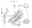
- Fig. 1 is a view schematically illustrating a heating device according to one embodiment of the present invention;
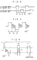
- Fig. 2 is a timing chart for explaining a biasing period of two electromagnets;
- Fig. 3 is a view illustrating a vibration waveform of a reflecting mirror;
- Fig. 4 shows the relationship among the vibration waveform of the reflecting mirror, a region to be heated, and a heating temperature distribution of the heated region;
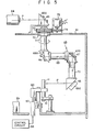
- Fig. 5 is a sectional view schematically illustrating the heating device according to another embodiment of the present invention;
- Fig. 6 is an enlarged sectional view of a support of the heating device of Fig. 5; and
- Fig. 7 is a view illustrating the vibration waveform of the reflecting mirror of the heating device of Fig. 5.
- A heating device which uses a laser beam will be described with reference to the accompanying drawings according to one embodiment of the present invention.
- Fig. 1 shows a process in which a predeter- . mined region of a quartz tube is entirely uniformly softened by the heating device according to the embodiment of the present invention.
- Referring to Fig. 1, the
reference numeral 10 denotes a chuck which supports aquartz tube 11 as an object to be heated, perpendicularly to the plane of thechuck 10. Thequartz tube 11 rotates in the direction indicated by anarrow 12 about the vertical central axis of thequartz tube 11. Aheating device 14 is spaced apart from thequartz tube 11 at a predetermined distance in order to heat aprospective heating region 13 of thequartz tube 11. - The
heating device 14 comprises a laser oscillator or laserbeam radiation device 15, first and second reflectingmirrors 16 and 17 which guide a laser beam P emitted from thelaser oscillator 15 to theregion 13, adrive mechanism 19 which pivotally vibrates the reflecting mirror 17 in the direction indicated byarrow 18, a free vibrationforce biasing mechanism 20 which biases the reflecting mirror 17 to assure free pivotal vibration, and acontroller 21 which controls the operation timing and period of laser beam emission from thelaser oscillator 15 and the operation timing and period of thedrive mechanism 19. - The
drive mechanism 19 is arranged in the manner to be described below. A support member or asupport column 32 extends from astationary member 31. One upper side of thesupport column 32 is flat. Apin 33 is fixed on the flat upper side to extend perpendicularly therefrom. Thepin 33 extends through a through hole which is formed in the central section of a side surface of a reflectingmirror support plate 34. Therefore, thesupport plate 34 is supported by thesupport member 32 so as to be pivotal about thepin 33. At the center of the upper surface of the reflectingmirror support plate 34 is supported the second reflecting mirror 17, the reflecting surface of which faces upward and which is parallel to the reflectingmirror support plate 34. The second reflecting mirror 17 may be pivotally moved with the reflectingmirror support plate 34. A magnetic body comprises a pair ofiron pieces 35a and 35b which are mounted to extend at both end of the reflectingmirror support plate 34 whose center is defined by thepin 33. The upper end of thesupport member 32 extends along the reflectingmirror support plate 34. A pair ofelectromagnets 36a and 36b which are spaced apart at a predetermined distance from theiron pieces 35a and 35b and which oppose theiron pieces 35a and 35b are mounted to the upper end of the reflectingmirror support plate 34. Theelectromagnets 36a and 36b are constituted by iron cores around the peripheries of which are respectively wound coils. When a DC current is supplied to theelectromagnets 36a and 36b, theelectromagnets 36a and 36b are energized to attract theiron pieces 35a and 35b. - The free vibration
force biasing mechanism 20 has arod 37 which extends perpendicularly to the reflectingmirror support plate 34 at the center of the lower surface thereof. A pair ofstationary pins 38a and 38b extend in opposite directions at the lower section of therod 37. Thestationary pins 38a and 38b are inserted in one end each of a pair ofcompression coil springs 39a and 39b which extend in the direction perpendicular to therod 37 and thepin 33, so that thestationary pins 38a and 38b respectively support thecompression coil springs 39a and 39b. A pair ofextended sections 40a and 40b are disposed, to oppose each other, and therod 37 is located at the center between theextended sections 40a and 40b on one side of thesupport member 32. Threaded holes are formed at the extendedsection 40a and 40b and adjust screws 41 a and 41 are screwed in the threaded holes to be coaxial with thestationary pins 38a and 38b. The base ends of theadjust screws 41 a and 41b extend outwardly, while the top ends thereof extend inwardly. Further, the top ends of the screws face thestationary pins 39a and 38b and support the other ends of thecompression coil springs 39a and 39b. Therefore, therod 37 is elastically pressed by thecompression coil springs 39a and 39b from both sides. With an adjustment of theadjust screws 41 a and 41 b, the biasing force or pressing force of thecompression coil springs 39a and 39b may be adjusted, so that the central position as shown in Fig. 1, that is, the distance between the electromagnet 36 and the iron piece 35a, is maintained equal to the distance between theelectromagnet 36b and theiron piece 35b. - The
controller 21 is constituted by a start switch 51; atimer switch 52 which makes thelaser oscillator 15 start the oscillation operation when the start switch 51 is turned on and which stops the oscillation operation when a predetermined period set by a timer elapses; a circuit which intermittently biases one electromagnet 36a during a period in which the start switch 51 is turned and then thelaser oscillator 15 stops oscillating, the biasing period of the electromagnet 36a being arbitrarily determined by atimer switch 53; a circuit which intermittently biases theother electromagnet 36b during a period in which the start switch 51 is turned on and thelaser oscillator 15 stops oscillating, the biasing period of theelectromagnet 36b being arbitrarily determined by atimer switch 54; and a timer switch 56 which determines a period in which one electromagnet 36a is deenergized and theother electromagnet 36b starts operating and a period in which theother electromagnet 36b is deenergized and one electromagnet 36a starts operating. - Referring to Fig. 1,
reference numeral 60 denotes a pincher which flattens the heated part of thequartz tube 11 by clamping it from both sides. - The mode of operation of the heating device with the above arrangement as shown in Fig. 1 will be described with reference to Figs. 2 to 4.
- With an operation of the
adjust screws 41 a and 41 b, the centers of reflectingmirror support plate 34 and the second reflecting mirror 17 are aligned. At the same time, positional adjustment in the vertical direction of thequartz tube 11 is performed by thechuck mechanism 10 so that the laser beam P reflected by the second reflecting mirror 17 is incident at the central area in the axial direction of the prospective softening region or theprospective heating region 13. Further, the distance between thequartz tube 11 and the second reflecting mirror 17 is adjusted in correspondence with the length in the axial direction of theprospective heating region 13 and a desired heating temperature distribution. For example, heating is performed so that a uniform temperature distribution is established throughout a length L in the axial direction of theprospective heating region 13; the distance described above is set so that a half-amplitude D of the laser beam P in theprospective heating region 13 satisfies the condition L:5 2D. When this distance is determined by the condition described above, thetimer switch 52 is set to a predetermined time, while the biasing periods of theelectromagnets 36a and 36b and the nonbiasing periods thereof are set by thetimer switches prospective heating region 13 uniformly, a biasing period T1 of one electromagnet 36a, a biasing period T2 of theother electromagnet 36b, and a nonbiasing period T3 must have a ratio of 1:1:1. - When the preparation as described above is completed, the
quartz tube 11 is rotated by thechuck mechanism 10 in the direction indicated by thearrow 12. At the same time, the start switch 51 is turned on. As a result, thelaser oscillator 15 is driven to emit the laser beam P. The laser beam P which is emitted by thelaser oscillator 15 is reflected through a right angle at the first reflectingmirror 16 and another right angle at the second reflecting mirror 17 and is incident on theprospective heating region 13. While the laser beam P is radiated on theprospective heating region 13, with the operation of the start switch 51, one electromagnet 36a is biased for the period T1, and theother electromagnet 36b is biased for the period T2 after the nonbiasing period T3 elapses. Subsequently, after the nonbiasing period T3, theother electromagnet 36b is biased again for the period T2, and the electromagnet 36a is then biased again for the period T1 after the nonbiasing period T3 elapses. In this manner, the same operation is repeated in which the biasing of theelectromagnets 36a and 36b is performed with the nonbiasing period T3 between. Therefore, theiron pieces 35a and 36b are alternatively attracted to theelectromagnets 36a and 36b, respectively, for a predetermined period. In response to this, the reflectingmirror support plate 34 and the second reflecting mirror 17 pivot about thepin 33. The second reflecting mirror 17 stops at the maximum tilted position for a period in which theiron pieces 35a and 35b are attracted to the corresponding electromagnets, for example, a period of about 1/10 second, as shown in Fig. 3. When this attraction is released, the movement of the second reflecting mirror 17 is damped by the biasing force of the compression springs 39a and 39b when the iron pieces are attracted. The second reflecting mirror 17 stops for the period in which the electromagnet is energized when the laser beam P is radiated on the end portion of theprospective heating region 13. For the nonbiasing period, the movement of the second reflecting mirror 17 is damped when the laser beam P is radiated on portions other than the end portion of theprospective heating region 13. As a result, the temperature drop caused by heat conduction of thequartz tube 11 is prevented in theprospective heating region 13. Therefore, as shown in Fig. 4, the heating temperature distribution in theprospective heating region 13 is kept substantially uniform. Referring to Fig. 4, symbol (a) denotes the vibration amplitude of the reflecting mirror; (b), theprospective heating region 13 of thequartz tube 11; and (c), the temperature distribution of theprospective heating region 13. , - As described above, in the heating device according to the above embodiment of the present invention, the vibration mode of the second reflecting mirror 17 is controlled while maintaining a constant output of the
laser oscillator 15, so that the predetermined region of the object to be heated may be heated with a constant temperature distribution, making the cost of the overall device low. - In the above embodiment, the periods T1, T2 and T3 are substantially the same to accomplish the uniform temperature distribution of the prospective heating region. However, these periods may be adjusted to accomplish various temperature distributions as needed. Alternatively, the temperature distribution may be varied by changing the vibration characteristics such as the damping frequency and the damping constant of the compressing springs since they influence the temperature distribution. The vibration characteristics may be easily changed by changing the pressing force of the compressing springs with the adjust screws or by adding a damper. In the embodiment described above, part of the waveform of the vibration of the reflecting mirror is determined as an accurate rectangular waveform. However, other waveforms in which the amplitude does not change for a predetermined period, such as a trapezoidal waveform, may be used. When a laser oscillator of high output, for example, several hundreds of watts or higher is used, the reflecting mirror is preferably cooled. In this case, cooling means such as a water cooling jacket may be mounted to the reflecting mirror support plate to accomplish this purpose. The device according to the embodiment as described above is used for the softening-pinching of the quartz tube. However, this heating device may also be used for other heating treatments such as a heat treatment of a metal. In the above embodiment, the object to be heated rotates. However, the reflecting mirror may rotate around the object to be heated while the object is kept stationary. Further, in the embodiment, the reflecting mirror is vibrated by a combination of the assembly of the electromagnet and the iron core, and the compression springs. However, the reflecting mirror may be vibrated by another means such as a cam, an example of which will be described with reference to Figs. 5 to 7.
- Referring to Fig. 5,
reference numeral 61 denotes a case in which thequartz tube 11 as the object to be heated is vertically supported by thechuck mechanism 10. The laser beam P is radiated on a predetermined region of the outer surface of thequartz tube 11 by a laserbeam radiation system 63. The laserbeam radiation system 63 has alaser oscillator 64 which is disposed outside thecase 61, and a first reflectingmirror 65 which is disposed above the upper wall of thecase 61, which reflects the laser beam P at right angles, and which is mounted to first support body 67a to guide the laser beam P into thecase 61 vertically, Further, within thecase 61 are mounted together so as to be freely movable: a second reflectingmirror 66 which is mounted to asecond support body 66a so as to guide the laser beam P from the first reflectingmirror 65 horizontally by reflecting the laser beam P at right angles; a third reflectingmirror 67 which is mounted to a third support body 67a so as to guide the laser beam P from the second reflectingmirror 65 vertically and downwardly by reflecting the laser beam P at right angles; and a fourth reflectingmirror 68 which is mounted to a fourth support body 68a so as to guide the laser beam P horizontally to thequartz tube 11 by reflecting the laser beam P at right angles. - The first reflecting
mirror 65 and the second reflectingmirror 66 are located above thequartz tube 11 so that the optical axes thereof are coaxial with the central axis of thequartz tube 11. The first support body 65a is stationary relative to the upper wall of thecase 61. Thesecond support body 66a is rotatably supported from the upper wall of thecase 61 and is mounted to the lower end of a verticalcylindrical body 71, the upper end of which extends through the upper wall. The rotating shaft of thecylindrical body 71 coincides with the optical axis of the first reflectingmirror 65. Alarge gear 73 is mounted to be coaxial with the rotating shaft of thecylindrical body 71, the end of which extends from the upper wall of thebase 61. Asmall gear 74 which is coaxial with the rotating shaft of amotor 75 meshes with thelarge gear 73. The resultant reduction gear train is driven by themotor 75 to rotate in the direction indicated by the arrow, and at the same time the second reflectingmirror 66 above thequartz tube 11 rotates in the direction indicated by the arrow about the central axis of thequartz tube 11 through thecylindrical body 71. - A horizontal
cylindrical body 69 between thesecond support body 66a and the third support body 67a, and a verticalcylindrical body 70 between the third support body 67a and the fourth support body 68a are disposed to support the support bodies at the ends of the horizontal and verticalcylindrical bodies second support body 66a rotates, the fourth support body 68a and simultaneously the fourth reflectingmirror 68 rotate around the periphery of thequartz tube 11 through the horizontalcylindrical body 69, the third support body 67a and the verticalcylindrical body 70. - A processing mechanism such as the
pincher 60 for deformation-processing of the heated portion of thequartz tube 11 is disposed in the vicinity of thechuck mechanism 10. Thepincher 60 is connected to ahydraulic cylinder piston 57 which is controlled by a hydraulic-controller 58. Therefore, when thehydraulic cylinder piston 57 moves upwardly, the heated portion of thequartz tube 11 is formed and pressed by thepincher 60. When the-forming is completed, thepincher 60 descends in accordance with the descending movement of thehydraulic cylinder piston 57. - Referring to Fig. 5,
reference numeral 59 denotes a control unit which controls thelaser oscillator 64, themotor 75, thehydraulic controller 58 and the drive mechanism which is disposed within the fourth support body 68a and which vibrates the fourth reflectingmirror 68 to be described later. - The fourth reflecting
mirror 68 is constituted by a concave mirror as shown in Fig. 6, and focuses . the laser beam P on the heated region. Theconcave mirror 68 is mounted at the central upper surface of a reflectingmirror support plate 80 in whichwater cooling jackets 81 are formed. The reflectingmirror support plate 80 is mounted to the fourth support body 68a so as to be pivotal about ahorizontal pin 82 at the center of the cross section of the reflectingmirror support plate 80. Acompression coil spring 82 is mounted between the fourth support body 68a and the lower surface of the reflectingmirror support plate 80 in the vicinity of one end so that thecompression coil spring 82 pivotally biases the reflectingmirror supporting plate 80 in the direction indicated by the arrow. A drivenelement 83 is mounted to the lower surface of the reflectingmirror support plate 80 in the vicinity of the other end, and engages with acam 84 which is rotatably supported by the fourth support body 68a. When thecam 84 is rotated by amotor 85, the reflectingmirror support plate 80 is free to vibrate through the drivenelement 83. The cam surface of thecam 84 is set to vibrate the reflectingmirror support plate 80 and simultaneously vibrate the fourth reflectingmirror 68 with a vibration waveform as shown in Fig. 7. The fourth reflectingmirror 68 stops at a position when the fourth reflectingmirror 68 pivots a maximum angle in the direction indicated by the arrow for the period T1. For the period T2, the fourth reflectingmirror 68 pivots a maximum angle in a direction opposite to the direction indicated by the arrow. At this position, the fourth reflectingmirror 68 stops for the nonbiasing period T3. During the period T2 in which the fourth reflectingmirror 68 pivots, the fourth reflectingmirror 68 pivots at a constant speed except for a temporary stop in the middle of the rotation. The ratio of periods T1, T2 and T3 is determined to be substantially equal. Even when the period T2 is set to be shorter than the periods T1 and T3, the heated region is entirely heated substantially uniformly, or the central portion may be heated slightly less than the other portions. - In the heating device with the arrangement according to the above embodiment of the present invention, since the fourth reflecting
mirror 68 rotates around thequartz tube 11 with the vibration pattern as shown in Fig. 7, the laser beam P transmitted to the fourth reflectingmirror 68 is radiated on the periphery of thequartz tube 11, by which the entire predetermined region is heated substantially uniformly.
Claims (9)
Applications Claiming Priority (2)
| Application Number | Priority Date | Filing Date | Title |
|---|---|---|---|
| JP185837/80 | 1980-12-26 | ||
| JP55185837A JPS5952037B2 (en) | 1980-12-26 | 1980-12-26 | Laser processing equipment |
Publications (3)
| Publication Number | Publication Date |
|---|---|
| EP0055463A2 EP0055463A2 (en) | 1982-07-07 |
| EP0055463A3 EP0055463A3 (en) | 1982-10-20 |
| EP0055463B1 true EP0055463B1 (en) | 1986-03-19 |
Family
ID=16177739
Family Applications (1)
| Application Number | Title | Priority Date | Filing Date |
|---|---|---|---|
| EP81110698A Expired EP0055463B1 (en) | 1980-12-26 | 1981-12-22 | Heating device |
Country Status (4)
| Country | Link |
|---|---|
| US (1) | US4429210A (en) |
| EP (1) | EP0055463B1 (en) |
| JP (1) | JPS5952037B2 (en) |
| DE (1) | DE3174157D1 (en) |
Families Citing this family (17)
| Publication number | Priority date | Publication date | Assignee | Title |
|---|---|---|---|---|
| FR2577052B1 (en) * | 1985-02-05 | 1988-09-09 | Bertin & Cie | METHOD AND DEVICE FOR MOVING THE POINT OF IMPACT OF A LASER BEAM ON A WORKPIECE |
| FR2583325B1 (en) * | 1985-06-17 | 1989-01-20 | Inst Mash Im | SCANNING DEVICE FOR A TECHNOLOGICAL LASER INSTALLATION |
| CA1284823C (en) * | 1985-10-22 | 1991-06-11 | Kenneth K. York | Systems and methods for creating rounded work surfaces by photoablation |
| SU1430931A1 (en) * | 1985-11-04 | 1988-10-15 | Институт Машиноведения Им.А.А.Благонравова | Scanner for process laser units |
| US4678422A (en) * | 1985-11-12 | 1987-07-07 | York Kenneth K | Systems and methods for precise, accurate formation of products by photoablation |
| FR2622710A1 (en) * | 1987-10-30 | 1989-05-05 | Sciaky Sa | Device for control of the pivoting of a tool, especially of a mirror for reflecting a laser beam |
| CA1325041C (en) * | 1988-08-15 | 1993-12-07 | Michael Peter Gaukroger | Cutting using high energy radiation |
| DE3850256T2 (en) * | 1988-11-18 | 1994-10-13 | Toyoda Machine Works Ltd | Method and device for treating a machined surface of a workpiece. |
| FR2691589B1 (en) * | 1992-05-20 | 1995-05-05 | Seram | Oscillating device for high power laser beams. |
| JP3060813B2 (en) * | 1993-12-28 | 2000-07-10 | トヨタ自動車株式会社 | Laser processing equipment |
| DE4430220C2 (en) * | 1994-08-25 | 1998-01-22 | Fraunhofer Ges Forschung | Method for controlling the laser beam intensity distribution on the surface of components to be processed |
| US6034803A (en) * | 1997-04-30 | 2000-03-07 | K2 T, Inc. | Method and apparatus for directing energy based range detection sensor |
| WO2009150210A2 (en) | 2008-06-11 | 2009-12-17 | Pantec Biosolutions Ag | Apparatus and method for the deflection of electromagnetic radiation, in particular of a laser beam |
| EP2133715A1 (en) * | 2008-06-11 | 2009-12-16 | Pantec Biosolutions AG | Device and method for deflecting an electromagnetic beam, in particular a laser beam |
| RU2487702C2 (en) * | 2009-05-12 | 2013-07-20 | Республиканское Унитарное производственное предприятие "Белмедпрепараты" | Medicine for treating tuberculosis |
| AT513467B1 (en) * | 2012-09-26 | 2014-07-15 | Trumpf Maschinen Austria Gmbh | Method for bending a workpiece |
| RU2618287C2 (en) * | 2015-08-04 | 2017-05-03 | Федеральное государственное бюджетное образовательное учреждение высшего образования "Казанский национальный исследовательский технический университет им. А.Н. Туполева - КАИ" (КНИТУ-КАИ) | Method of laser treatment of article (versions) and device for its implementation (versions) |
Family Cites Families (5)
| Publication number | Priority date | Publication date | Assignee | Title |
|---|---|---|---|---|
| US3225206A (en) | 1962-03-14 | 1965-12-21 | Borg Warner | Photosensitive inspection apparatus for filamentary material |
| CH468083A (en) * | 1968-02-09 | 1969-01-31 | Siemens Ag | Method for the shape-changing processing of a crystalline body made of semiconductor material, in particular a silicon single crystal |
| US4107528A (en) * | 1972-06-13 | 1978-08-15 | Daniel Silverman | Method and apparatus for transferring a pattern on an overlying web by laser burning onto an underlying web |
| US3848104A (en) | 1973-04-09 | 1974-11-12 | Avco Everett Res Lab Inc | Apparatus for heat treating a surface |
| US4063064A (en) * | 1976-02-23 | 1977-12-13 | Coherent Radiation | Apparatus for tracking moving workpiece by a laser beam |
-
1980
- 1980-12-26 JP JP55185837A patent/JPS5952037B2/en not_active Expired
-
1981
- 1981-12-21 US US06/332,829 patent/US4429210A/en not_active Expired - Fee Related
- 1981-12-22 EP EP81110698A patent/EP0055463B1/en not_active Expired
- 1981-12-22 DE DE8181110698T patent/DE3174157D1/en not_active Expired
Also Published As
| Publication number | Publication date |
|---|---|
| EP0055463A3 (en) | 1982-10-20 |
| US4429210A (en) | 1984-01-31 |
| DE3174157D1 (en) | 1986-04-24 |
| JPS5952037B2 (en) | 1984-12-17 |
| EP0055463A2 (en) | 1982-07-07 |
| JPS57109589A (en) | 1982-07-08 |
Similar Documents
| Publication | Publication Date | Title |
|---|---|---|
| EP0055463B1 (en) | Heating device | |
| US6640604B2 (en) | Laser bending method and apparatus for bending a work piece in normal and reverse directions | |
| US5303081A (en) | Laser beam scanner | |
| US8434341B2 (en) | Methods and systems for supporting a workpiece and for heat-treating the workpiece | |
| KR20050084974A (en) | Scribe line forming device and scribe line forming method | |
| JP2022528291A (en) | Machining equipment for laser machining of workpieces and methods for laser machining of workpieces | |
| US3277266A (en) | Apparatus for hard coating metal surfaces | |
| US4856858A (en) | Optical scanner | |
| JP3456424B2 (en) | Laser welding method and laser welding apparatus | |
| JP3821105B2 (en) | Optical means driving device | |
| US5034953A (en) | Laser device capable of making a temperature distribution uniform in a slab-shaped laser medium | |
| KR100650922B1 (en) | Laser welding equipment | |
| JPH04501583A (en) | Equipment for producing amorphous ceramic products or metal alloys | |
| KR100354044B1 (en) | Optic head of laser system for heating treatment | |
| JPH0669928U (en) | Laser beam oscillator device | |
| US6198066B1 (en) | Method and apparatus for radiated beam marking of a golf club part and such part | |
| US4873410A (en) | Parallel gap welder | |
| EP0427441B1 (en) | Objective lens actuator | |
| JP3590946B2 (en) | Multi-degree-of-freedom processing stage equipment | |
| KR20250074440A (en) | Laser processing system | |
| JP3425162B2 (en) | Micro-moving device using impact force caused by thermal deformation of thermal deformation element | |
| EP0688062A2 (en) | Adjustable fresnel zone plate | |
| CN222994825U (en) | Optical and mechanical system | |
| JP2002096188A (en) | Laser beam machine and laser beam machining method | |
| JPH1197781A (en) | Laser light reflecting device and optical device having the same |
Legal Events
| Date | Code | Title | Description |
|---|---|---|---|
| PUAI | Public reference made under article 153(3) epc to a published international application that has entered the european phase |
Free format text: ORIGINAL CODE: 0009012 |
|
| AK | Designated contracting states |
Designated state(s): DE GB NL |
|
| PUAL | Search report despatched |
Free format text: ORIGINAL CODE: 0009013 |
|
| AK | Designated contracting states |
Designated state(s): DE GB NL |
|
| 17P | Request for examination filed |
Effective date: 19830411 |
|
| RAP1 | Party data changed (applicant data changed or rights of an application transferred) |
Owner name: KABUSHIKI KAISHA TOSHIBA |
|
| GRAA | (expected) grant |
Free format text: ORIGINAL CODE: 0009210 |
|
| AK | Designated contracting states |
Kind code of ref document: B1 Designated state(s): DE GB NL |
|
| REF | Corresponds to: |
Ref document number: 3174157 Country of ref document: DE Date of ref document: 19860424 |
|
| PLBE | No opposition filed within time limit |
Free format text: ORIGINAL CODE: 0009261 |
|
| STAA | Information on the status of an ep patent application or granted ep patent |
Free format text: STATUS: NO OPPOSITION FILED WITHIN TIME LIMIT |
|
| 26N | No opposition filed | ||
| PGFP | Annual fee paid to national office [announced via postgrant information from national office to epo] |
Ref country code: NL Payment date: 19871231 Year of fee payment: 7 |
|
| PGFP | Annual fee paid to national office [announced via postgrant information from national office to epo] |
Ref country code: DE Payment date: 19890131 Year of fee payment: 8 |
|
| PG25 | Lapsed in a contracting state [announced via postgrant information from national office to epo] |
Ref country code: GB Effective date: 19891222 |
|
| PG25 | Lapsed in a contracting state [announced via postgrant information from national office to epo] |
Ref country code: NL Effective date: 19900701 |
|
| NLV4 | Nl: lapsed or anulled due to non-payment of the annual fee | ||
| GBPC | Gb: european patent ceased through non-payment of renewal fee | ||
| PG25 | Lapsed in a contracting state [announced via postgrant information from national office to epo] |
Ref country code: DE Effective date: 19900901 |