EP0054968A2 - Dispositif pour le stockage de résidus d'éléments combustibles nucléaires émettant de la chaleur et disposés dans des récipients - Google Patents
Dispositif pour le stockage de résidus d'éléments combustibles nucléaires émettant de la chaleur et disposés dans des récipients Download PDFInfo
- Publication number
- EP0054968A2 EP0054968A2 EP81110712A EP81110712A EP0054968A2 EP 0054968 A2 EP0054968 A2 EP 0054968A2 EP 81110712 A EP81110712 A EP 81110712A EP 81110712 A EP81110712 A EP 81110712A EP 0054968 A2 EP0054968 A2 EP 0054968A2
- Authority
- EP
- European Patent Office
- Prior art keywords
- storage
- pallet
- zone
- rails
- side walls
- Prior art date
- Legal status (The legal status is an assumption and is not a legal conclusion. Google has not performed a legal analysis and makes no representation as to the accuracy of the status listed.)
- Granted
Links
Images
Classifications
-
- G—PHYSICS
- G21—NUCLEAR PHYSICS; NUCLEAR ENGINEERING
- G21F—PROTECTION AGAINST X-RADIATION, GAMMA RADIATION, CORPUSCULAR RADIATION OR PARTICLE BOMBARDMENT; TREATING RADIOACTIVELY CONTAMINATED MATERIAL; DECONTAMINATION ARRANGEMENTS THEREFOR
- G21F9/00—Treating radioactively contaminated material; Decontamination arrangements therefor
- G21F9/28—Treating solids
- G21F9/34—Disposal of solid waste
Definitions
- the invention relates to a device for storing spent, heat-emitting and enclosed nuclear reactor fuel elements, which are arranged horizontally within buildings and cooled by a gas stream. are, the building having a storage and a loading zone.
- Spent fuel assemblies must be kept safe until they are reprocessed.
- a bearing is described in DE-OS 29 06 629, in which fuel elements enclosed in containers are cooled by a gas stream.
- the gas flow is brought in from outside the building and leaves the building after flowing around the receiving positions.
- the openings provided in the walls and in the ceiling can damage the stored fuel elements from outside.
- the recording positions extend in the horizontal direction and are accessible from one side. Since two containers are arranged one behind the other in a receiving position, but the receiving positions are only accessible from one side, the loading and unloading of the containers is cumbersome.
- This device does not require horizontal false ceilings as support elements for the storage rack units.
- the hindrance of the cooling gas flow is kept to a minimum.
- the loading and unloading process can be carried out simply by sliding on the rails and being accessible from the opposite side walls. Due to the stacked rows of pallets, which form a heating register known from boiler construction, the cooling gas requirement is easy to determine.
- the rails are preferably fastened to intermediate walls which extend between the side walls and divide the storage zone into disk-shaped sections.
- This design ensures that the cooling gas flow can flow freely from the bottom to the top.
- the walls are provided with openings to improve gas circulation.
- the pallet trucks are equipped with damping elements at their mutual points of contact.
- the storage zone and the loading zone each have a separate gas circuit in order not to transfer any contamination of the storage zone to the loading zone.
- At least one spindle elevator provided with a lifting platform is arranged on the sides of its side walls facing away from the storage zone, the lifting platform having rails for receiving the pallet trucks and being equipped with a pushing device acting in the direction of the rails for moving the pallet trucks along the rails.
- the pallet trolleys can already be inserted into a storage level from the lifting platform on rails.
- a storage level is designed as a return path for the pallet truck within each disk-shaped storage section.
- a lifting platform is arranged at both ends of this storage floor.
- a pallet truck located on the storage floor is pushed onto the lifting platform located at the opposite end of the floor.
- the device according to the invention is described on the basis of the schematic FIGS. 1-4 and an exemplary embodiment.
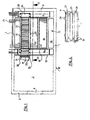
- a building structure which is closed on all sides and consists of walls 1, 2, a ceiling 3 and a base 4 gives a storage zone 5, two loading zones 6, 6a and a preparation zone 7.Only the preparation zone 7 adjacent to the loading zone 5a has a 2 in its outer wall Gate 8, through which fuel elements enclosed in container 9 enter the interior of the building 10 or from this to the outside.
- the storage zone 5 is separated from the loading zones 6, 6a by the side walls 11.
- a partition 12 is arranged between the feed zone 6a and the preparation zone 7.
- Four partition walls 13 extend from one side wall 11 of the storage zone to the other and, apart from openings 14 for better cooling gas circulation, extend from the sole 4 to the ceiling 3 of the building in their vertical extent.
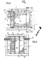
- the loading zones 6, 6a each have a spindle elevator 22, 22a, which along the same side of the side walls 11 facing away from the storage zone is movable both in the vertical direction and in the horizontal direction via guide rails 23.
- Each spindle elevator is provided with a lifting platform 24. It is also equipped with rails 20 which have the same track width as the rails arranged in the sections.
- the pallet truck 21 shown in FIG. 4 on a larger scale consists of a pallet 25 which is provided with wheels 27 via axles 26 and is equipped with damping elements 28 at its possible points of contact with other pallet trucks.
- a pallet truck with three containers 9 is loaded with a crane system 29 located in the preparation zone 7. Spacers 30, which can be designed as damping elements, serve to secure the position of the containers.
- the now loaded pallet truck 21 is lifted by the crane system 29 onto a platform 31 which is also equipped with rails 20 of the track width of the pallet truck.
- the pedestal is connected to the partition 12, which has a recess 32 at the level of the pedestal for the passage of the pallet truck.
- the recess 32 is continued in a bracket 33 which projects into the loading zone to such an extent that the lifting platform 24 can still be moved past it at a short distance during its upward movement.
- the recess and the console are provided with rails that align with those of the platform.
- the sections 15 also serve to store unloaded pallet trucks.
- the first containers 9 loaded with spent fuel elements are delivered, they are therefore fully loaded with empty pallet trolleys on all storage floors 34, except for the lowest one with its inclined rail profile.
- Only one pallet truck is located in the preparation zone 7. It is loaded there with three containers 9 and lifted onto the platform 33. Now the lifting platform 24 of the spindle elevator 22a is brought to the height of the bracket 33 and by moving the spindle elevator 22a across the guide rails 23, the rails 20 of the platform, console and lifting platform are brought into alignment. The pallet truck is not using manipulation devices shown pushed onto the lifting platform.
- the lifting platform is positioned in relation to the storage level to be loaded by vertical and / or horizontal movement of the spindle elevator.
- the lifting platform of the spindle elevator 22 arranged in the loading zone 6 is brought into position at the opposite end of this storage level. After the closures 16 assigned to each storage level have been removed, the openings 17 in the side walls 11 are exposed and the corresponding storage level is accessible from both sides.
- an intermediate piece, not shown is inserted to connect the rails 20 of the storage floor to the rails 20 of the lifting platform 24, an intermediate piece, not shown, is inserted.
- a pushing device arranged on the lifting platform, but also not shown, pushes the pallet trolley 21 loaded with three containers one trolley length into the storage level. As a result, an empty pallet truck 21 is inevitably pushed onto the lifting platform located there at the opposite end of the storage level.
- the spindle elevator 22 now positions the lifting platform to the lower storage level designed as a return path 35.
- the pallet carriage After the pallet carriage has been pushed into this return path by a pushing device (not shown) by one carriage length, it will automatically roll to the other end due to the inclination of the return path.
- the pallet truck will roll onto the lifting platform of the spindle elevator 22a, which is meanwhile positioned there.
- the spindle elevator 22a carries it to the height of the console 33 from where it is brought onto the platform 31.
- the crane 29 brings it to the preparation zone 7 for the loading process. From there, the described loading is repeated until all storage floors are loaded with loaded pallet trucks.
- the process takes place in such a way that an empty pallet trolley is pushed into the corresponding storage level from the loading zone 6a, thereby pushing out a loaded pallet trolley at the other end and in the manner described via the return path 35 is removed.
- the storage zone is used in an optimal way, as it can accommodate both loaded and empty pallet trucks.
- the loading and unloading process is straightforward.
- the stored containers are cooled by a closed gas flow in the natural train, the circulation of which runs in the direction of arrow 36 and is optimized by the openings 14.
- the absorbed heat is given off by the gas flow to a plurality of heat pipe bundles 19 which then forward again outside the building 10, the loading zones 6, 6a and the storage zone 5 point Cooling circuits on, which give their heat to separate heat pipe bundles.
- a further improvement of the cooling is achieved by a separate cooling circuit (arrow direction 37), which dissipates the heat collecting under the ceiling 3.
Landscapes
- Engineering & Computer Science (AREA)
- Environmental & Geological Engineering (AREA)
- Physics & Mathematics (AREA)
- General Engineering & Computer Science (AREA)
- High Energy & Nuclear Physics (AREA)
- Warehouses Or Storage Devices (AREA)
- Monitoring And Testing Of Nuclear Reactors (AREA)
Priority Applications (1)
| Application Number | Priority Date | Filing Date | Title |
|---|---|---|---|
| AT81110712T ATE11973T1 (de) | 1980-12-24 | 1981-12-23 | Einrichtung zur lagerung abgebrannter, waermeabgebender und in behaeltern eingeschlossener kernreaktorbrennelemente. |
Applications Claiming Priority (2)
| Application Number | Priority Date | Filing Date | Title |
|---|---|---|---|
| DE3049141A DE3049141C2 (de) | 1980-12-24 | 1980-12-24 | Gebäude zur strahlenabgeschirmten Lagerung von in Behältern eingeschlossenen radioaktiven Kernreaktor-Brennelementen |
| DE3049141 | 1980-12-24 |
Publications (3)
| Publication Number | Publication Date |
|---|---|
| EP0054968A2 true EP0054968A2 (fr) | 1982-06-30 |
| EP0054968A3 EP0054968A3 (en) | 1982-09-01 |
| EP0054968B1 EP0054968B1 (fr) | 1985-02-20 |
Family
ID=6120361
Family Applications (1)
| Application Number | Title | Priority Date | Filing Date |
|---|---|---|---|
| EP81110712A Expired EP0054968B1 (fr) | 1980-12-24 | 1981-12-23 | Dispositif pour le stockage de résidus d'éléments combustibles nucléaires émettant de la chaleur et disposés dans des récipients |
Country Status (3)
| Country | Link |
|---|---|
| EP (1) | EP0054968B1 (fr) |
| AT (1) | ATE11973T1 (fr) |
| DE (1) | DE3049141C2 (fr) |
Cited By (2)
| Publication number | Priority date | Publication date | Assignee | Title |
|---|---|---|---|---|
| US4889681A (en) * | 1981-10-19 | 1989-12-26 | U.S. Tool & Die, Inc. | Apparatus for reducing floor and seismic loadings in underwater storage areas used in the storing of spent nuclear fuel rods |
| US5152958A (en) * | 1991-01-22 | 1992-10-06 | U.S. Tool & Die, Inc. | Spent nuclear fuel storage bridge |
Families Citing this family (1)
| Publication number | Priority date | Publication date | Assignee | Title |
|---|---|---|---|---|
| DE3916359C2 (de) * | 1989-05-19 | 2002-07-04 | Siemens Ag | Einrichtung zur horizontalen Lagerung eingebüchster Brennelemente |
Family Cites Families (4)
| Publication number | Priority date | Publication date | Assignee | Title |
|---|---|---|---|---|
| US3663817A (en) * | 1969-07-28 | 1972-05-16 | Fmc Corp | Radioactive waste storage system and method |
| DE2837839C2 (de) * | 1978-08-30 | 1984-04-26 | Kraftwerk Union AG, 4330 Mülheim | Einrichtung zur wartungsfreien Lagerung von radioaktivem Material |
| DE2929467C2 (de) * | 1979-07-20 | 1985-04-25 | Kraftwerk Union AG, 4330 Mülheim | Lagergebäude für abgebrannte Kernreaktorbrennelemente |
| FR2484685A1 (fr) * | 1980-06-13 | 1981-12-18 | Commissariat Energie Atomique | Installation de stockage d'assemblages combustibles irradies |
-
1980
- 1980-12-24 DE DE3049141A patent/DE3049141C2/de not_active Expired
-
1981
- 1981-12-23 EP EP81110712A patent/EP0054968B1/fr not_active Expired
- 1981-12-23 AT AT81110712T patent/ATE11973T1/de not_active IP Right Cessation
Cited By (2)
| Publication number | Priority date | Publication date | Assignee | Title |
|---|---|---|---|---|
| US4889681A (en) * | 1981-10-19 | 1989-12-26 | U.S. Tool & Die, Inc. | Apparatus for reducing floor and seismic loadings in underwater storage areas used in the storing of spent nuclear fuel rods |
| US5152958A (en) * | 1991-01-22 | 1992-10-06 | U.S. Tool & Die, Inc. | Spent nuclear fuel storage bridge |
Also Published As
| Publication number | Publication date |
|---|---|
| EP0054968B1 (fr) | 1985-02-20 |
| ATE11973T1 (de) | 1985-03-15 |
| DE3049141A1 (de) | 1982-07-08 |
| EP0054968A3 (en) | 1982-09-01 |
| DE3049141C2 (de) | 1986-10-30 |
Similar Documents
| Publication | Publication Date | Title |
|---|---|---|
| EP0628124B1 (fr) | Dispositif de stockage d'objets dans un bloc d'entreposage | |
| EP0083026B1 (fr) | Stockage à sec pour éléments combustibles irradiés d'un réacteur nucléaire | |
| DE2829325B2 (de) | Hochregal für Paletten | |
| DE69216629T2 (de) | Parkvorrichtung für kraftfahrzeuge | |
| AT408893B (de) | Einrichtung zum raumsparenden abstellen von kraftfahrzeugen | |
| DE4338717A1 (de) | Automatische Park- und Lagereinrichtung für Kraftfahrzeuge | |
| AT410438B (de) | Lagermagazin | |
| DE3613904C2 (fr) | ||
| DE8816927U1 (de) | Lageranlage | |
| EP0054968B1 (fr) | Dispositif pour le stockage de résidus d'éléments combustibles nucléaires émettant de la chaleur et disposés dans des récipients | |
| CH661494A5 (de) | Einrichtung zum ein- und auslagern von paletten. | |
| DE4444925C2 (de) | Parkeinrichtung, insbesondere nach Art eines Hochregallagers | |
| DE2756385C2 (fr) | ||
| DE4306241C2 (de) | Vorrichtung zum Speichern von Gegenständen in einem Lagerblock | |
| EP0154667A1 (fr) | Dispositif de stockage et d'enlèvement de récipients en utilisant un système de stockage | |
| DE9301506U1 (de) | Hochregallager für Container | |
| DE3934967C2 (fr) | ||
| EP0798238A2 (fr) | Système d'entreposage pour palettes pour objets longs | |
| EP0271009B1 (fr) | Système de stockage avec magasin et dispositifs de convoyage | |
| DE4224855C2 (de) | Parksystem zum Ein- und Ausparken von Fahrzeugen | |
| DE19932814B4 (de) | Mehrebenen-Parkanlage für Fahrzeuge | |
| DE2814887C2 (de) | Einrichtung zur Lagerung von länglichen Kernreaktor-Brennelementen in einem wassergefüllten Becken | |
| DE2730812A1 (de) | Wagen zum transportieren von brennelement-transportbehaeltern | |
| DE2215859B2 (de) | Magazinbauteil | |
| EP0367168A1 (fr) | Casier à bouteilles |
Legal Events
| Date | Code | Title | Description |
|---|---|---|---|
| PUAI | Public reference made under article 153(3) epc to a published international application that has entered the european phase |
Free format text: ORIGINAL CODE: 0009012 |
|
| PUAL | Search report despatched |
Free format text: ORIGINAL CODE: 0009013 |
|
| AK | Designated contracting states |
Designated state(s): AT CH FR GB IT LI |
|
| AK | Designated contracting states |
Designated state(s): AT CH FR GB IT LI |
|
| 17P | Request for examination filed |
Effective date: 19830225 |
|
| ITF | It: translation for a ep patent filed | ||
| GRAA | (expected) grant |
Free format text: ORIGINAL CODE: 0009210 |
|
| AK | Designated contracting states |
Designated state(s): AT CH FR GB IT LI |
|
| REF | Corresponds to: |
Ref document number: 11973 Country of ref document: AT Date of ref document: 19850315 Kind code of ref document: T |
|
| ET | Fr: translation filed | ||
| PLBE | No opposition filed within time limit |
Free format text: ORIGINAL CODE: 0009261 |
|
| STAA | Information on the status of an ep patent application or granted ep patent |
Free format text: STATUS: NO OPPOSITION FILED WITHIN TIME LIMIT |
|
| 26N | No opposition filed | ||
| PGFP | Annual fee paid to national office [announced via postgrant information from national office to epo] |
Ref country code: AT Payment date: 19861113 Year of fee payment: 6 |
|
| PG25 | Lapsed in a contracting state [announced via postgrant information from national office to epo] |
Ref country code: GB Effective date: 19881223 Ref country code: AT Effective date: 19881223 |
|
| ITTA | It: last paid annual fee | ||
| GBPC | Gb: european patent ceased through non-payment of renewal fee | ||
| PGFP | Annual fee paid to national office [announced via postgrant information from national office to epo] |
Ref country code: FR Payment date: 19891124 Year of fee payment: 9 |
|
| PG25 | Lapsed in a contracting state [announced via postgrant information from national office to epo] |
Ref country code: LI Effective date: 19891231 Ref country code: CH Effective date: 19891231 |
|
| REG | Reference to a national code |
Ref country code: CH Ref legal event code: PL |
|
| PG25 | Lapsed in a contracting state [announced via postgrant information from national office to epo] |
Ref country code: FR Effective date: 19910830 |
|
| REG | Reference to a national code |
Ref country code: FR Ref legal event code: ST |