EP0054825B1 - Locking device - Google Patents
Locking device Download PDFInfo
- Publication number
- EP0054825B1 EP0054825B1 EP19810110223 EP81110223A EP0054825B1 EP 0054825 B1 EP0054825 B1 EP 0054825B1 EP 19810110223 EP19810110223 EP 19810110223 EP 81110223 A EP81110223 A EP 81110223A EP 0054825 B1 EP0054825 B1 EP 0054825B1
- Authority
- EP
- European Patent Office
- Prior art keywords
- locking
- bolt
- locking device
- housing
- wall
- Prior art date
- Legal status (The legal status is an assumption and is not a legal conclusion. Google has not performed a legal analysis and makes no representation as to the accuracy of the status listed.)
- Expired
Links
Images


Classifications
-
- B—PERFORMING OPERATIONS; TRANSPORTING
- B62—LAND VEHICLES FOR TRAVELLING OTHERWISE THAN ON RAILS
- B62D—MOTOR VEHICLES; TRAILERS
- B62D33/00—Superstructures for load-carrying vehicles
- B62D33/02—Platforms; Open load compartments
- B62D33/023—Sideboard or tailgate structures
- B62D33/027—Sideboard or tailgate structures movable
- B62D33/037—Latching means therefor
Definitions
- the invention relates to a locking device for folding walls, shutters, doors or the like, in particular for foldable side walls of vehicles or vehicle trailers which are at an angle to one another, with a housing displaceable, spring-loaded locking bolt which is used for axial displacement from the closed position into the Free position of a positively engaging lever against the spring action is to be actuated for attachment to a wall element and a cooperating eyelet on another wall element.
- Known locking devices for folding walls, folding shutters, folding doors are, for example, the pivotable angle lever, the angled leg of which fits into an eyelet and can be secured there with a split pin.
- Other devices assume an over-center lock, in which a locking eyelet or a locking claw grips behind a second claw.
- these locking devices have the disadvantage that they have to be closed individually, the often the folding wall having to be held with one hand while the locking device is brought into engagement and locked with the other. This procedure allows a safe locking of foldable drop sides in the created state; it is disadvantageous, however, that locking and unlocking each take both hands. Even if two locking devices for locking or unlocking the folding wall are within reach, both must be released or locked one after the other.
- Both DE-A-2444.021 and DE-U-6 811 961 disclose interlocks of wall elements which are in alignment or in one plane.
- the sleeves with which the bolts interact are to be arranged above the wall, so that on the one hand further construction of the wall is impeded or made impossible, cannot be reached if the tarpaulin is covered and one of the walls is high person standing next to the vehicle can be reached.
- such known locking devices can also be used for locking two wall elements which are at an angle to one another, they are nevertheless provided with the disadvantages mentioned.
- a locking device of the generic type which is characterized by a housing with an angled eyelet arm receptacle and rear guide arranged in the rear housing wall for the locking bolt and a plate dividing the housing into two rooms (the eyelet arm receptacle and the bolt receptacle) , in which the front guide of the locking bolt is arranged, wherein the locking bolt is provided at a distance from the front guide with a pin driver and its spring is arranged between this pin driver and the rear housing wall and also a shell covering the free housing side, which has a pivot axis is connected to the top of the housing and with its angled, the free sides of the housing overlapping sides is connected via the bolt driver with the locking bolt and is formed in its rear region as a grip shell, the locking eye on her An arm is provided with an offset.
- the locking bolt is provided with a collar that rests in the limit position on the rear side of the housing.
- the bolt driver of the locking bolt is designed as a stroke limiter that supports itself in the limit position against the plate.
- the insertion opening of the eyelet arm receptacle for the eyelet arm is advantageously provided with a collar, the collar expediently having a bulge which overlaps the edge of the insertion opening of the eyelet arm receptacle.
- the collar with the bead is advantageously designed as a one-piece molding and is advantageously made of plastic.
- This traction device can be designed as a two-part train.
- a twist grip is advantageously provided, with which the trains of the two-part train are engaged.
- a particular advantage of the subject of Invention is that such a locking device is extremely compact and compact, takes up little space, especially according to the length and height, and that this locking device due to its special design with little construction and thus inexpensive manufacture an excellent encapsulation of the mechanical parts guaranteed. This ensures that these mechanical parts are protected against any environmental influences, be it dirt, rain, ice or mechanical stress.
- the housing in the form of a shell, which is also provided with a front, angled eyelet holder, which is also particularly well protected, and by designing the actuating handle also in the form of a shell, which engages over the inner shell formed by the housing and in particular on the still open ones If this covers, a closed design is achieved for such a locking device, as was previously unknown or possible.
- Figure 1 shows the fixed side wall 11 and the movable side wall 12, which are detachably connected to each other with the locking device according to the invention.
- the eyelet part is screwed to the fixed side wall 11 and the locking part of the locking device is screwed to the movable side wall 12, the eyelet part 3 being fastened to the side plate 11 with its fastening plate 30 using the screws 33.
- the locking part is screwed to the side flaps of the housing 20, which are arranged on the side of the eyelet arm receptacle 28, by means of the screws 27 on the front side with the movable board plate 12, the offset 31 bridges the difference in height and allows proper insertion of the eyelet arine 32 (FIG 2) into the eyelet arm receptacle 28.
- the eyelet arm receptacle 28 of the housing 20 of the locking part 2 of the locking device is approximately at right angles to the housing 20 and thus encompasses the corresponding edge of the movable side wall 12.
- the part of the housing 20 facing away from the eyelet arm receptacle 28 becomes the handle shell here 21.1 trained shell covered.
- This grip shell is pivoted about the axis 24 to the housing 20 and connected to the bolt driver 25 with the locking bolt.
- a pivoting of the grip shell 21.1 about the pivot axis 24 consequently results in a movement of the pin driver 25 along a circular path section about the axis of rotation 24.
- Figure 2 shows the same situation, but in the open state.
- the movable side wall 12 is only slightly angled with respect to the fixed side wall 11 in order to better illustrate the interaction of the locking part 2 and the eyelet part 3 of the locking device.
- the eyelet arm 32 with the eye 32.1, in which the locking bolt engages - not shown in FIG. 2 - is located outside the eyelet arm receptacle 28.
- the handle 21.1 to be pivoted about the axis 24 to unlock it is already in its rest position, the limit position.
- the rear housing part with the rear housing wall 20.1 can be seen almost completely covered by the grip shell.
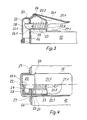
- Figures 3, 4 and 5 each show the locking part 2 of the locking device in a different view. In Figure 3 a section of the bolt part is shown.
- the housing 20 is fastened on the movable side wall 12 with the eyelet arm receptacle 28 which is essentially at right angles thereto. Screw 27.1 and screws 27 (FIGS. 4 and 5) are used for fastening.
- the shell covering the housing is designed as a grip shell 21.1 and the pivot axis 24 is formed by a bolt which has rivets on both sides, for example.
- the locking bolt 22 is arranged, which is guided by the opening in the rear housing wall 20.1 and the cover plate 26 and is held in the limit position by the spring 23.
- the spring cotter pin required to transmit the spring force to the locking bolt is transformed into the bolt driver 25 in the exemplary embodiment.
- the force of the spring 23 is transmitted to the locking bolt 22 via this bolt driver.
- the bolt driver 25 establishes a connection to the pivotable handle shell 21.1 and, when the handle shell 21.1 is pivoted about its pivot axis 24, moves on a circular arc corresponding to the pivot angle about the same axis.
- the locking bolt 22 is moved so that the spring 23 is tensioned. If the grip shell 21.1 is released, the spring force predominates, and the locking bolt 22 - including the grip shell 21.1 connected to it via the bolt driver 25 - is pressed into the limit position by the spring 23.
- This limit position is given in the selected embodiment in that the rear collar 22.2 of the locking bolt 22 lies against the rear housing wall 20.1.
- Figure 4 shows a half section of the bolt part the locking device in the direction perpendicular to Figure 3.
- the three fastening screws namely the two screws 27 next to the eyelet arm receptacle and the screw 27.1 under the handle shell 21.1 can be seen.
- the locking bolt 22 is pressed into its limit position by the spring 23, the collar 22.2 abutting the rear housing side 20.1.
- the spring split pin which is designed as a pin driver 25, is still clearly in front of the wall 26 covering the eyelet arm receptacle 28.
- the insertion opening of the eyelet arm receptacle 28 is provided with a collar 29, which extends outward into a bead 29.1 which overlaps the edge of the insertion opening. This can be seen in FIG. 5 from the opposite viewing direction to FIG.
- the insertion opening for the eyelet arm is limited by the inserted collar 29 so that the eyelet arm has little play.
- the bead 29.1 which extends outwards, protects the lower edge of the eyelet arm receptacle.
- the control bolt 22 can be seen in the depth of the slot exposed by the insertion opening.
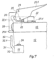
- FIGS. 6 and 7 correspond in their representation to FIG. 3, the eyelet part 3 fastened to the fixed side wall 11 and its interaction with the locking part 2 being shown here.
- Figure 6 shows the state in which the fixed side wall 11 and the movable side wall 12 are locked together.
- the locking bolt 22 grips into the eye 32.1 (FIG. 7) of the eyelet arm 32, which was inserted through the insertion opening of the eyelet arm receptacle when the insertion firstly hits the front edge of the eyelet arm 32 on the sliding bevel 22.1 (FIG. 3) of the locking bolt 22 and presses it via a wedge action against the force of the spring 23 back from the limit position so far that the eyelet arm 32 can slide past the front edge of the locking bolt 22.
- FIG. 8 shows a special exemplary embodiment with the pairwise opposing arrangement of two locking devices with central actuation.
- the two oppositely arranged locking parts of the locking device 2 'and 2 "are located on both sides of the movable side wall 12, which is pivotably attached to the vehicle floor with the hinges (not shown in more detail in FIG. 8).
- a pulling linkage with the two end parts 41.1 and 41.2 connects the two locking bolts which are arranged under the shells 21. Both locking bolts are each held in limit position by a spring, as shown in Figures 5 and 6.
- the parts 41.1 and 41.2 of the rod which can be moved in opposite directions by the turning handle 42, act the locking bolts so that both locking bolts are pulled back against the spring direction when turning the handle 42.
- the locking device proposed according to the invention does not require any additional manual operation if the movable side wall is to be locked: when the flap slams shut, it engages automatically. This is a very important advantage if, for example, live animals are to be transported, which, due to their restlessness, press against the movable side wall and thus cause difficulties when closing.
- the side wall is firmly locked during transport, since no force component can be pushed back under the type of load.
- Additional locks such as insertable split pins or the like are conceivable, but they can generally be dispensed with.
- the movement of the side walls towards one another due to driving over not always well-developed roads and paths could cause the locking device to strike and thus lead to undesirable noise development.
- the collar of the eyelet arm receptacle which surrounds the eyelet arm, prevents lateral movements and thus noises.
- the vibration dampers provided between the foldable side wall and the edges of the fixed side walls absorb movements of the foldable side wall in the folding direction and, due to their elastic restoring forces, give a pretension which ultimately acts as force transmitted from the eye of the eyelet arm to the locking bolt.
- This force lock bolt and eyelet are fixed against each other.
- the pretensioning prevents both the folding side wall from hitting the edges of the fixed side walls and a hitting inside the locking device.
- the simple structure of the locking device allows economical manufacture, and what is particularly important for motor vehicle trailers set up for transporting animals, the locking devices can be fitted in such a way that no protruding parts are necessary on the inside of the side walls. As a result, the risk of injury to the animals - naturally also the risk of damage to non-live transport goods - can be prevented.
- the measures for suppressing undesirable noise development which are possible with the new locking device are not only measures to protect the environment, they are also a wear protection which substantially determines the durability of the locking device and its operational safety.
Description
Die Erfindung betrifft eine Verriegelungsvorrichtung für Klappwände, -läden, -türen o. dergl., insbesondere für klappbare Bordwände von Fahrzeugen oder Fahrzeuganhängern, die im Winkel zueinander stehen, mit einem Gehäuse verschieblichen, federbelasteten Riegelbolzen, der zur axialen Verschiebung von der Schließstellung in die Frei-Stellung von einem formschlüssig angreifenden Hebel gegen die Federwirkung zu betätigen ist, zur Anbringung an einem Wandelement und eine damit zusammenwirkende Öse an einem anderen Wandelement.The invention relates to a locking device for folding walls, shutters, doors or the like, in particular for foldable side walls of vehicles or vehicle trailers which are at an angle to one another, with a housing displaceable, spring-loaded locking bolt which is used for axial displacement from the closed position into the Free position of a positively engaging lever against the spring action is to be actuated for attachment to a wall element and a cooperating eyelet on another wall element.
Bekannte Verriegelungsvorrichtungen für Klappwände, Klappläden, Klapptüren, insbesondere solche, die beim Bau von Kraftfahrzeugen bzw. Kraftfahrzeuganhängern benutzt werden, sind beispielsweise der schwenkbare Winkelhebel, dessen abgewinkelter Schenkel in eine Öse faßt und dort mit einem Splint gesichert werden kann. Andere Vorrichtungen gehen von einem Übertotpunktverschluß aus, bei dem eine Verriegelungsöse oder eine Verriegelungskrälle hinter eine zweite Kralle faßt. Diese Verriegelungsvorrichtungen haben jedoch den Nachteil, daß sie einzeln geschlossen werden müssen, wobei die oftmals die Klappwand mit der einen Hand gehalten werden muß, während mit der anderen die Verschlußvorrichtung in Eingriff gebracht und gesperrt wird. Dieses Vorgehen erlaubt ein sicheres Verriegeln klappbarer Bordwände im angelegten Zustand ; nachteilig ist jedoch, daß das Verriegeln ebenso wie das Entriegeln jeweils beide Hände in Anspruch nimmt. Selbst wenn zwei Verriegelungseinrichtungen zum Verschließen oder Lösen der Klappwand in Reichweite sind, müssen beide nacheinander gelöst oder verriegelt werden.Known locking devices for folding walls, folding shutters, folding doors, in particular those used in the construction of motor vehicles or motor vehicle trailers, are, for example, the pivotable angle lever, the angled leg of which fits into an eyelet and can be secured there with a split pin. Other devices assume an over-center lock, in which a locking eyelet or a locking claw grips behind a second claw. However, these locking devices have the disadvantage that they have to be closed individually, the often the folding wall having to be held with one hand while the locking device is brought into engagement and locked with the other. This procedure allows a safe locking of foldable drop sides in the created state; it is disadvantageous, however, that locking and unlocking each take both hands. Even if two locking devices for locking or unlocking the folding wall are within reach, both must be released or locked one after the other.
Grundsätzlich bestehen zwei Möglichkeiten zwei im Winkle zueinander stehende Wandelemente miteinander zu verriegeln, wobei allgemein bzw. in der Mehrzahl der Fälle davon auszugehen ist, daß es sich bei dem einem Wandelement um eine abklappbare Fahrzeug-Rückwand handelt :
- 1. Der Verriegelungsbolzen steht senkrecht : Dann ist es gleichgültig, ob er an der Rückwand oder an der Seitenwand angeordnet ist.
- 2. Der Verriegelungsbolzen liegt waagerecht : Dann muß er an der beweglichen Wand, also an der Rückwand angeordnet sein.
- 1. The locking bolt is vertical: Then it does not matter whether it is arranged on the rear wall or on the side wall.
- 2. The locking bolt lies horizontally: Then it must be arranged on the movable wall, ie on the rear wall.
Sowohl aus der DE-A-2444.021 als auch der DE-U-6 811 961 sind Verriegelungen von in einer Flucht bzw. in einer Ebene zueinander stehenden Wandelementen bekannt. Bei der dabei verwendeten senkrechten Anordnung der Verriegelungsbolzen sind die Hülsen, mit denen die Bolzen zusammenwirken, über der Wand anzuordnen, so daß einerseits ein weiterer Aufbau der Wand behindert bzw. unmöglich gemacht ist, bei überdeckter Plane nicht erreichbar ist und bei hohen Fahrzeugwänden von einer neben dem Fahrzeug stehenden Person erreichbar sind. Wenngleich derartige bekannte Verriegelungsvorrichtungen auch für die Verriegelung von zwei im Winkel zueinander stehender Wandelemente verwendbar sind, sind sie jedoch mit den benannten Nachteilen versehen.Both DE-A-2444.021 and DE-U-6 811 961 disclose interlocks of wall elements which are in alignment or in one plane. In the case of the vertical arrangement of the locking bolts used, the sleeves with which the bolts interact are to be arranged above the wall, so that on the one hand further construction of the wall is impeded or made impossible, cannot be reached if the tarpaulin is covered and one of the walls is high person standing next to the vehicle can be reached. Although such known locking devices can also be used for locking two wall elements which are at an angle to one another, they are nevertheless provided with the disadvantages mentioned.
Hier setzt die Erfindung ein, ihr liegt die Aufgabe zugrunde eine Verriegelungseinrichtung anzugeben, die beim Schließen der Klappwände selbsttätig einrastet, einhändig zu lösen ist, wirtschaftlich herstellbar ist und die darüber hinaus betriebssicher eingesetzt werden kann. Ihr liegt weiter die Aufgabe zugrunde, bei paarweiser und gegenständiger Anordnung der erfindungsgemäßen Verriegelungsvorrichtung eine Zentralbetätigung dafür vorzuschlagen. Diese Aufgabe wird nach der Erfindung durch eine Verriegelungsvorrichtung der gattungsgemäßen Art gelöst, die gekennzeichnet ist durch ein Gehäuse mit abgewinkelter Ösenarmaufnahme und in der rückwärtigen Gehäusewand angeordnete hinterer Führung für den Riegelbolzen sowie eine das Gehäuse in zwei Räume (die Ösenarmaufnahme und die Bolzenaufnahme) unterteilende Platte, in der die vordere Führung des Riegelbolzens angeordnet ist, wobei der Riegelbolzen im Abstand von der vorderen Führung mit einem Bolzenmitnehmer versehen ist und seine Feder zwischen diesem Bolzenmitnehmer und der rückwärtigen Gehäusewand angeordnet ist und weiterhin eine die freie Gehäuseseite abdeckende Schale, die über eine Schwenkachse mit der Oberseite des Gehäuses verbunden ist und mit ihren abgewinkelten, die freien Seiten des Gehäuses übergreifenden Seiten über den Bolzenmitnehmer mit dem Riegelbolzen verbunden ist und in ihrem rückwärtigen Bereich als Griffschale ausgebildet ist, wobei die Verschlußöse an ihrem Ösenarm mit einer Abkröpfung versehen ist.This is where the invention comes in; it is based on the object of specifying a locking device which engages automatically when the folding walls are closed, can be released with one hand, is economical to produce and can also be used in a reliable manner. It is also the object of proposing a central actuation for it in pairs and opposing arrangement of the locking device according to the invention. This object is achieved according to the invention by a locking device of the generic type, which is characterized by a housing with an angled eyelet arm receptacle and rear guide arranged in the rear housing wall for the locking bolt and a plate dividing the housing into two rooms (the eyelet arm receptacle and the bolt receptacle) , in which the front guide of the locking bolt is arranged, wherein the locking bolt is provided at a distance from the front guide with a pin driver and its spring is arranged between this pin driver and the rear housing wall and also a shell covering the free housing side, which has a pivot axis is connected to the top of the housing and with its angled, the free sides of the housing overlapping sides is connected via the bolt driver with the locking bolt and is formed in its rear region as a grip shell, the locking eye on her An arm is provided with an offset.
Der Riegelbolzen ist mit einem in Grenzlage an der rückwärtigen Gehäuseseite anliegenden Bund versehen. Der Bolzenmitnehmer des Riegelbolzens ist als sich in Grenzlage gegen die Platte aufstützender Hubbegrenzer ausgebildet. Die Einführöffnung der Ösenarmaufnahme für den Ösenarm ist vorteilhaft mit einem Kragen versehen, wobei der Kragen zweckmäßig eine die Kante der Einführöffnung der Ösenarmaufnahme übergreifende Wulst aufweist. Vorteilhaft ist der Kragen mit der Wulst als einstückiges Formstück ausgebildet und besteht zweckmäßig aus Kunststoff.The locking bolt is provided with a collar that rests in the limit position on the rear side of the housing. The bolt driver of the locking bolt is designed as a stroke limiter that supports itself in the limit position against the plate. The insertion opening of the eyelet arm receptacle for the eyelet arm is advantageously provided with a collar, the collar expediently having a bulge which overlaps the edge of the insertion opening of the eyelet arm receptacle. The collar with the bead is advantageously designed as a one-piece molding and is advantageously made of plastic.
Bei paarweise gegenständiger Anordnung der Verriegelungsvorrichtungen auf einer Klappwand ist eine deren Riegelbolzen verbindene Zugeinrichtung vorgesehen. Diese Zugeinrichtung kann als zweiteiliger Zug ausgebildet sein. Vorteilhaft ist ein Drehgriff vorgesehen, mit dem die Züge des zweiteiligen Zuges in Eingriff sind.When the locking devices are arranged in pairs opposite one another on a folding wall, a pulling device connecting their locking bolts is provided. This traction device can be designed as a two-part train. A twist grip is advantageously provided, with which the trains of the two-part train are engaged.
Ein besonderer Vorteil des Gegenstandes der Erfindung besteht darin, daß eine derartige Verriegelungsvorrichtung äußerst gedrängt und kompakt aufgebaut ist, nur geringen Raum in Anspruch nimmt und zwar insbesondere nach der Länge und nach der Höhe und daß diese Verriegelungsvorrichtung aufgrund ihrer besonderen Bauart bei geringem Bauaufwand und damit preisgünstige Herstellung eine hervorragende Abkapselung der mechanischen Teile gewährleistet. Damit ist ein Schutz dieser mechanischen Teile gegen jegliche Einflüsse der Umwelt, sei es Schmutz, Regen, Eis oder seien es auch mechanische Beanspruchungen, sichergestellt.A particular advantage of the subject of Invention is that such a locking device is extremely compact and compact, takes up little space, especially according to the length and height, and that this locking device due to its special design with little construction and thus inexpensive manufacture an excellent encapsulation of the mechanical parts guaranteed. This ensures that these mechanical parts are protected against any environmental influences, be it dirt, rain, ice or mechanical stress.
Durch die Ausbildung des Gehäuses in Schalenform, das noch dazu mit einer vorderen, abgewinkelten Ösenaufnahme die damit ebenfalls besonders gut geschützt ist versehen ist und durch Ausbildung des Betätigungsgriffes ebenfalls in Schalenform, der die innere durch das Gehäuse gebildete Schale übergreift und insbesondere an den noch offenen Stellen dieses abdeckt, ist eine geschlossene Bauart für eine derartige Verriegelungsvorrichtung erreicht, wie das bislang noch nicht bekannt oder ermöglicht war.By designing the housing in the form of a shell, which is also provided with a front, angled eyelet holder, which is also particularly well protected, and by designing the actuating handle also in the form of a shell, which engages over the inner shell formed by the housing and in particular on the still open ones If this covers, a closed design is achieved for such a locking device, as was previously unknown or possible.
Das Wesen der Erfindung wird im folgenden anhand eines Ausführungsbeispieles mit Bezug auf die Figuren 1 bis 8 näher erläutert. Im einzelnen zeigen :
- Figur 1 eine perspektivische Ansicht der geschlossenen Verriegelungsvorrichtung ;
Figur 2 eine perspektivische Ansicht der geöffneten Verriegelungsvorrichtung ;Figur 3 Verriegelungsvorrichtung, horizontal geschnitten ;- Figur 4 Verriegelungsvorrichtung, seitliche Ansicht, halbseitig geschnitten ;
- Figur 5 Ösenarmaufnahme, Einführungsöffnung für den Ösenarm mit Kragen und Wulst ;
- Figur 6 Verriegelungsvorrichtung geschlossen, halb geschnitten;
- Figur 7 Verriegelungsvorrichtung geöffnet, halb geschnitten ;
- Figur 8 abklappbare Bordwand mit paarweiser gegenständiger Anordnung der Verriegelungsvorrichtung und zentraler Entriegelung.
- Figure 1 is a perspective view of the closed locking device;
- Figure 2 is a perspective view of the opened locking device;
- Figure 3 locking device, cut horizontally;
- Figure 4 locking device, side view, cut on one side;
- Figure 5 eyelet arm holder, insertion opening for the eyelet arm with collar and bead;
- Figure 6 locking device closed, half cut;
- Figure 7 locking device opened, half cut;
- Figure 8 foldable drop side with paired opposing arrangement of the locking device and central unlocking.
Im einzelnen zeigt Figur 1 die feste Bordwand 11 und die bewegbare Bordwand 12, die mit der neuerungsgemäßen Verriegelungsvorrichtung lösbar miteinander verbunden sind. Dazu sind an der festen Bordwand 11 der Ösenteil und an der bewegbaren Bordwand 12 der Riegelteil der Verriegelungsvorrichtung verschraubt, wobei der Ösenteil 3 mit seiner Befestigungsplatte 30 mit Hilfe der Schrauben 33 an der Bordplatte 11 befestigt ist. Der Riegelteil ist mit den seitlichen Lappen des Gehäuses 20, die auf der Seite der Ösenarmaufnahme 28 angeordnet sind, mit Hilfe der Schrauben 27 stirnseitig mit der bewegbaren Bordplatte 12 verschraubt, die Abkröpfung 31 überbrückt die Höhendifferenz und erlaubt ein ordnungsgemäßes Einführen des Ösenarins 32 (Figur 2) in die Ösenarmaufnahme 28. Die Ösenarmaufnahme 28 des Gehäuses 20 des Riegelteiles 2 der Verriegelungseinrichtung steht etwa rechtwinklig zum Gehäuse 20 und umgreift somit die korrespondierende Kante der bewegbaren Bordwand 12. Der der Ösenarmaufnahme 28 abgewandte Teil des Gehäuses 20 wird von der hier als Griffschale 21.1 ausgebildeten Schale überdeckt. Diese Griffschale ist um die Achse 24 schwenkbar an das Gehäuse 20 angelenkt und mit dem Bolzenmitnehmer 25 mit dem Riegelbolzen verbunden. Ein Schwenken der Griffschale 21.1 um die Schwenkachse 24 hat demzufolge eine Bewegung des Bolzenmitnehmers 25 längs eines Kreisbahnabschnittes um die Drehachse 24 zur Folge. Die Figur 2 zeigt die gleiche Situation, jedoch in geöffnetem Zustand. Die bewegbare Bordwand 12 ist gegenüber der festen Bordwand 11 nur leicht abgewinkelt, um das Zusammenwirken des Riegelteiles 2 und des Ösenteiles 3 der Verriegelungseinrichtung besser zu verdeutlichen. Der Ösenarm 32 mit dem Auge 32.1, in das der - in Figur 2 nicht dargestellte - Riegelbolzen eingreift, befindet sich außerhalb der Ösenarmaufnahme 28. Die zum Entriegeln um die Achse 24 zu schwenkende Griffschale 21.1 ist bereits wieder in ihrer Ruhestellung, der Grenzlage. Von der Griffschale nahezu verdeckt ist das rückwärtige Gehäuseteil mit der rückwärtigen Gehäusewand 20.1 zu erkennen. Die Figuren 3, 4 und 5 zeigen den Verriegelungsteil 2 der Verriegelungsvorrichtung jeweils in anderer Ansicht. In Figur 3 ist ein Schnitt des Riegelteiles dargestellt. Auf der bewegbaren Bordwand 12 ist das Gehäuse 20 mit der im wesentlichen rechtwinklig dazu stehenden Ösenarmaufnahme 28 befestigt. Zur Befestigung dienen die Schraube 27.1 sowie die Schrauben 27 (Figuren 4 und 5). Die das Gehäuse abdeckende Schale ist als Griffschale 21.1 ausgebildet und die Schwenkachse 24 wird durch einen Bolzen gebildet, der beispielsweise beidseitig Vernietungen aufweist. Im Inneren des Gehäuses 20 ist der Riegelbolzen 22 angeordnet, der von der Öffnung in der rückwärtigen Gehäusewand 20.1 und der Abdeckplatte 26 geführt und von der Feder 23 in Grenzlage gehalter wird. Der zur Übertragung der Federkraft auf den Riegelbolzen notwendige Federsplint ist in dem Ausführungsbeispiel zum Bolzenmitnehmer 25 umgebildet. Über diesen Bolzenmitnehmer wird einmal die Kraft der Feder 23 auf den Riegelbolzen 22 übertragen. Zum anderen stellt der Bolzenmitnehmer 25 eine Verbindung zur schwenkbaren Griffschale 21.1 her und bewegt sich, wenn die Griffschale 21.1 um ihre Schwenkachse 24 geschwenkt wird, auf einem dem Schwenkwinkel entsprechenden Kreisbogen um die gleiche Achse. Dabei wird der Riegelbolzen 22 so bewegt, daß die Feder 23 gespannt wird. Wird die Griffschale 21.1 freigegeben, überwiegt die Federkraft, und der Riegelbolzen 22 - einschließlich der mit ihm über den Bolzenmitnehmer 25 verbundenen Griffschale 21.1 - wird von der Feder 23 in Grenzlage gedrückt. Diese Grenzlage ist in dem gewählten Ausführungsbeispiel dadurch gegeben, daß der hintere Bund 22.2 des Riegelbolzens 22 sich gegen die rückwärtige Gehäusewand 20.1 legt. Die Figur 4 zeigt einen Halbschnitt des Riegelteils der Verriegelungsvorrichtung in zu Figur 3 rechtwinkliger Blickrichtung. In dieser Darstellung sind die drei Befestigungsschrauben, nämlich die beiden Schrauben 27 neben der Ösenarmaufnahme und die Schraube 27.1 unter der Griffschale 21.1 zu erkennen. Der Riegelbolzen 22 wird von der Feder 23 in seine Grenzlage gedrückt, wobei der Bund 22.2 an der rückwärtigen Gehäuseseite 20.1 anliegt. In dieser Grenzlage liegt der als Bolzenmitnehmer 25 ausgebildete Federsplint noch deutlich vor der die Ösenarmaufnahme 28 abdeckenden Wand 26. Die Einführöffnung der Ösenarmaufnahme 28 ist mit einem Kragen 29 versehen, der sich nach außen in eine die Kante der Einführöffnung übergreifende Wulst 29.1 fortsetzt. Dies ist in Figur 5 aus zu Figur 4 entgegengesetzter Blickrichtung zu erkennen. Die Einführöffnung für den Ösenarm ist durch den eingelegten Kragen 29 so begrenzt, daß der Ösenarm kein großes Spiel hat. Die nach außen übergreifende Wulst 29.1 schützt die untere Kante der Ösenarmaufnahme. In der Tiefe des von der Einführöffnung freigegebenen Schlitzes ist der Regelbolzen 22 erkennbar.In detail, Figure 1 shows the
Die Figuren 6 und 7 entsprechen in ihrer Darstellung der Figur 3, wobei hier der an der festen Bordwand 11 befestigte Ösenteil 3 und sein Zusammenwirken mit dem Riegelteil 2 dargestellt ist. Figur 6 zeigt den Zustand, in dem die feste Bordwand 11 und die bewegbare Bordwand 12 miteinander verriegelt sind. Der Riegelbolzen 22 faßt dabei in das Auge 32.1 (Figur 7) des Ösenarms 32, der durch die Einführöffnung der Ösenarmaufnahme eingeführt wurde beim Einführen stößt zunächst die vordere Kante des Ösenarmes 32 auf die Aufgleitschräge 22.1 (Figur 3) des Riegelbolzens 22, und drückt diesen über eine Keilwirkung gegen die Kraft der Feder 23 aus der Grenzlage so weit zurück, daß der Ösenarm 32 an der vorderen Kante des Riegelbolzens 22 vorbeigleiten kann. Wegen der durch die Einführöffnung 26.1 in der Abdeckplatte 26 im Zusammenwirken mit der Führungsöffnung für den Riegelbolzen 22 in der rückwärtigen Gehäusewand 20,1 gegebenen guten Führung kann der Riegelbolzen bei weiterem Einführen des Ösenarmes 32 in das Auge 32.1 einfallen. Da in Gegenrichtung keine Schräge zur Verfügung steht, gibt es auch keine Keilwirkung. Eine entgegensetzt wirkende, auf ein Öffnen der bewegbaren Bordwand gerichtete Kraft bleibt somit ohne Wirkung : wichtig dabei ist, daß der Riege bolzen selbst gegen Verdrehen gesichert ist, was durch die Bolzenmitnahme 25 gewährleistet ist. Diese Kraft ist im wesentlichen die elastische Rückstellkraft des Schwingungsdämpfers 34, der die beim Aneinanderschlagen der Bordwände entstehenden lästigen Geräusche unterbinden soll. Die Hubbegrenzung in dem hier dargestellten Fall wird im Gegensatz zur Darstellung in den Figuren 3 und 4 nicht über einen Bund 22.2 (Figur 3 und 4) am Riegelbolzen 22 erreicht, sondern durch das Anlegen der Kontur der Griffschale 21.1 an die obere Kontur 20.2 (Figur 3) des Gehäuses 20, wodurch eine weitere Begrenzung des Hubes des Riegelbolzens und somit seine Grenzlage gegeben ist. In Figur 7 ist die Griffschale 21.1 ausgeschwenkt. Der Bolzenmitnehmer 25 hat den Riegelbolzen 22 gegen die Federkraft zurückgezogen ; die Feder 23 ist gespannt. Bei der axialen in Richtung auf die rückwärtige Gehäuseseite gerichteten Bewegung des Riegelbolzens 22 gleitet er aus dem Auge 32.1 des Ösenarmes 32 und gibt diesen Ösenarm frei. Somit kann die bewegbare Bordwand 12 abgeklappt werden, der Ösenarm 32 verläßt die Ösenarmaufnahme 28 und die die Schwingungen unterdrückenden Schwingungsdämpfer 34 gewinnen ihre entspannte Form zurück.FIGS. 6 and 7 correspond in their representation to FIG. 3, the
Schließlich zeigt die Figur 8 ein besonderes Ausführungsbeispiel mit der paarweisen gegenständigen Anordnung zweier Verriegelungsvorrichtungen mit zentraler Betätigung. Auf beiden Seiten der bewegbaren Bordwand 12, die mit den - in der Figur 8 nicht näher bezeichneten - Scharnieren am Fahrzeugboden schwenkbar befestigt ist, befinden sich die beiden gegenständig angeordneten Riegelteile der Verriegelungsvorrichtung 2' und 2". Ein Zuggestänge mit den beiden Endteilen 41.1 und 41.2 verbindet beide Riegelbolzen miteinander, die unter den Schalen 21 angeordnet sind. Beide Riegelbolzen werden - wie in den Figuren 5 und 6 dargestellt - mit jeweils einer Feder in Grenzlage gehalten. Die durch den Drehgriff 42 gegensinnig bewegbaren Teile 41.1 und 41.2 des Zugestänges wirken auf die Riegelbolzen so, daß beim Drehen des Griffes 42 beide Riegelbolzen gegen die Federrichtung zurückgezogen werden. Dabei gleiten die Spitzen der Riegelbolzen aus den Augen der beiden Ösenarme, die Verriegelung ist somit aufgehoben und die bewegbare Klappwand kann um die Scharniere geschwenkt werden. Beim Schließen läuft der Vorgang automatisch ab : Die bewegbare Klappwand wird gegen die festen Wände 11 geschwenkt, die Ösenarme 32 mit den Augen 32.1 gleiten in die Ösenarmaufnahmen 28 der Riegelteile 2' und 2" auf der bewegbaren Klappwand 12. Die vorderen Enden beider Ösenarme stoßen auf die Aufgleitschrägen 22.1 beider Riegelbolzen 22, infolge der auftretenden Keilwirkung werden beiden Riegelbolzen 22 gegen die Wirkung der Federn zurückgedrückt bis die Augen in die Position gekommen sind, daß beide Riegelbolzen in ihre Grenzlage schnellen. Damit sind beide Verriegelungsvorrichtungen eingerastet und die Klappwand 12 ist verriegelt.Finally, FIG. 8 shows a special exemplary embodiment with the pairwise opposing arrangement of two locking devices with central actuation. The two oppositely arranged locking parts of the
Die nach der Erfindung vorgeschlagene Verriegelungsvorrichtung bedarf keiner zusätzlichen Handbetätigung wenn die bewegbare Bordwand verriegelt werden soll: beim Zuschlagen der Klappe erfolgt ein selbsttätiges Einrasten. Dies ist ein sehr wesentlicher Vorteil, wenn beispielsweise lebende Tiere transportiert werden sollen, die, bedingt durch ihre Unruhe, gegen die bewegbare Bordwand drücken und so Schwierigkeiten beim Schließen entstehen lassen. Während des Transportes ist die Bordwand fest verriegelt, da bei der Art der Belastung keine den Riegel zurückschiebende Kraftkomponente auftreten kann. Zusätzliche Sperren, etwa einführbare Splinte oder dergleichen sind zwar denkbar, auf sie kann jedoch im Regelfall verzichtet werden. Die durch das Fahren über auch nicht immer gut ausgebaute Straßen und Wege bedingte Bewegung der Bordwände gegeneinander könnte zu einem Schlagen der Verriegelungsvorrichtung, und damit zu einer unerwünschten Geräuschentwicklung führen. Der den Ösenarm umfassende Kragen der Ösenarmaufnahme verhindert seitliche Bewegungen und somit auch dadurch bedingte Geräusche. Die zwischen der klappbaren Bordwand und den Kanten der festen Bordwände vorgesehenen Schwingungsdämpfer fangen Bewegungen der klappbaren Bordwand in Klapprichtung auf und geben aufgrund ihrer elastischen Rückstellkräfte eine Vorspannung, die als Kraft letztendlich vom Auge des Ösenarms übetragen auf den Riegelbolzen wirkt. Durch diese Kraft sind Riegelbolzen und Ösenarm gegeneinander fixiert. Auch hier wird durch die Vorspannung ein « Schlagen sowohl der klappbaren Bordwand gegen die Kanten der feststehenden Bordwände, als auch ein « Schlagen innerhalb der Verriegelungsvorrichtung unterbunden. Der einfache Aufbau der Verriegelungsvorrichtung gestattet ein wirtschaftliches Herstellen, wobei, was besonders für zum Transport von Tieren eingerichtete Kraftfahrzeuganhänger bedeutsam ist, die Verriegelungsvorrichtungen so angebracht werden können, daß auf der Innenseite der Bordwände keinerlei vorstehenden Teile notwendig sind. Dadurch kann die Verletzungsgefahr der Tiere - naturgemäß auch die Beschädigungsgefahr für nicht lebende Transportgüter - unterbunden werden. Die bei der neuerungsgemäßen Verriegelungsvorrichtung möglichen Maßnahmen zur Unterdrückung unerwünschter Geräuschentwicklung ist nicht nur eine dem Schutze der Umwelt dienende Maßnahme, sie ist darüberhinaus ein Verschleißschutz der die Haltbarkeit der Verriegelungsvorrichtung und ihre Betriebssicherheit wesentlich mit bestimmt.The locking device proposed according to the invention does not require any additional manual operation if the movable side wall is to be locked: when the flap slams shut, it engages automatically. This is a very important advantage if, for example, live animals are to be transported, which, due to their restlessness, press against the movable side wall and thus cause difficulties when closing. The side wall is firmly locked during transport, since no force component can be pushed back under the type of load. To Additional locks, such as insertable split pins or the like are conceivable, but they can generally be dispensed with. The movement of the side walls towards one another due to driving over not always well-developed roads and paths could cause the locking device to strike and thus lead to undesirable noise development. The collar of the eyelet arm receptacle, which surrounds the eyelet arm, prevents lateral movements and thus noises. The vibration dampers provided between the foldable side wall and the edges of the fixed side walls absorb movements of the foldable side wall in the folding direction and, due to their elastic restoring forces, give a pretension which ultimately acts as force transmitted from the eye of the eyelet arm to the locking bolt. This force lock bolt and eyelet are fixed against each other. Here, too, the pretensioning prevents both the folding side wall from hitting the edges of the fixed side walls and a hitting inside the locking device. The simple structure of the locking device allows economical manufacture, and what is particularly important for motor vehicle trailers set up for transporting animals, the locking devices can be fitted in such a way that no protruding parts are necessary on the inside of the side walls. As a result, the risk of injury to the animals - naturally also the risk of damage to non-live transport goods - can be prevented. The measures for suppressing undesirable noise development which are possible with the new locking device are not only measures to protect the environment, they are also a wear protection which substantially determines the durability of the locking device and its operational safety.
Claims (10)
Applications Claiming Priority (2)
| Application Number | Priority Date | Filing Date | Title |
|---|---|---|---|
| DE19808033182 DE8033182U1 (en) | 1980-12-13 | 1980-12-13 | LOCKING DEVICE |
| DE8033182U | 1980-12-13 |
Publications (2)
| Publication Number | Publication Date |
|---|---|
| EP0054825A1 EP0054825A1 (en) | 1982-06-30 |
| EP0054825B1 true EP0054825B1 (en) | 1986-07-09 |
Family
ID=6721379
Family Applications (1)
| Application Number | Title | Priority Date | Filing Date |
|---|---|---|---|
| EP19810110223 Expired EP0054825B1 (en) | 1980-12-13 | 1981-12-08 | Locking device |
Country Status (3)
| Country | Link |
|---|---|
| EP (1) | EP0054825B1 (en) |
| DE (1) | DE8033182U1 (en) |
| DK (1) | DK155210C (en) |
Cited By (1)
| Publication number | Priority date | Publication date | Assignee | Title |
|---|---|---|---|---|
| CN105383356A (en) * | 2015-11-16 | 2016-03-09 | 三一汽车制造有限公司 | Rotary locking device and dumper provided with same |
Families Citing this family (7)
| Publication number | Priority date | Publication date | Assignee | Title |
|---|---|---|---|---|
| DE8033182U1 (en) * | 1980-12-13 | 1981-05-21 | Westfalia-Werke Franz Knöbel & Söhne KG, 4840 Rheda-Wiedenbrück | LOCKING DEVICE |
| ATE23304T1 (en) * | 1983-08-25 | 1986-11-15 | Hesterberg & Soehne Gmbh & Co | LOCKING DEVICE FOR SIDE PANELS OF COMMERCIAL VEHICLES. |
| NZ208163A (en) * | 1984-09-15 | 1988-08-30 | Barry Herbert Gwynne | Gate lock: tongue held in magnetically keyed lock |
| ZA941659B (en) * | 1993-03-11 | 1994-10-12 | Pretorius Izak J | Locking assembly for closures having laterally movable styles and closures embodying same |
| SE506373C2 (en) * | 1996-04-29 | 1997-12-08 | Rosen Goran | Handle for locking or locking. for maneuvering folding flat clamps |
| EP2952417B1 (en) * | 2014-06-05 | 2017-08-02 | Club Car, LLC | Full width tailgate release handle |
| US11648880B1 (en) * | 2017-12-05 | 2023-05-16 | Jondavid George Roise | Barbecue grill with docking plate |
Family Cites Families (8)
| Publication number | Priority date | Publication date | Assignee | Title |
|---|---|---|---|---|
| BE567768A (en) * | ||||
| US1431758A (en) * | 1920-06-22 | 1922-10-10 | Brodie J Richardson | Hand-bag lock |
| CH115664A (en) * | 1925-02-25 | 1926-07-01 | Bilstein August Fa | Cremone bolt. |
| FR1261587A (en) * | 1960-06-23 | 1961-05-19 | Semi-automatic gear drive with flexible cable for windows or other applications | |
| DE6811961U (en) * | 1968-12-18 | 1969-04-30 | Ackermann Fahrzeugbau | SIDE PANEL CLOSURE FOR PLATFORM SUPPORTS OF TRUCKS AND TRAILERS |
| SE379701B (en) * | 1973-09-27 | 1975-10-20 | G Rosen | |
| FR2427449A1 (en) * | 1978-06-02 | 1979-12-28 | Renault | Bolt fixing for utility vehicle coachwork - has pivoting locking lever held by stops one of which is spring loaded |
| DE8033182U1 (en) * | 1980-12-13 | 1981-05-21 | Westfalia-Werke Franz Knöbel & Söhne KG, 4840 Rheda-Wiedenbrück | LOCKING DEVICE |
-
1980
- 1980-12-13 DE DE19808033182 patent/DE8033182U1/en not_active Expired
-
1981
- 1981-12-08 EP EP19810110223 patent/EP0054825B1/en not_active Expired
- 1981-12-10 DK DK546681A patent/DK155210C/en not_active IP Right Cessation
Cited By (2)
| Publication number | Priority date | Publication date | Assignee | Title |
|---|---|---|---|---|
| CN105383356A (en) * | 2015-11-16 | 2016-03-09 | 三一汽车制造有限公司 | Rotary locking device and dumper provided with same |
| CN105383356B (en) * | 2015-11-16 | 2018-01-19 | 三一汽车制造有限公司 | Rotating locking apparatus and the dumper for being equiped with the rotating locking apparatus |
Also Published As
| Publication number | Publication date |
|---|---|
| DE8033182U1 (en) | 1981-05-21 |
| DK546681A (en) | 1982-06-14 |
| EP0054825A1 (en) | 1982-06-30 |
| DK155210B (en) | 1989-03-06 |
| DK155210C (en) | 1989-07-10 |
Similar Documents
| Publication | Publication Date | Title |
|---|---|---|
| DE7539577U (en) | GAS SPRING WITH MECHANICAL LOCKING | |
| DE3235891A1 (en) | CHILDLESS DOOR LOCK | |
| DE3336952C2 (en) | Lock for glove compartment flaps in motor vehicles | |
| DE3825594C2 (en) | ||
| DE3135401C2 (en) | Locking device for a door with a one-piece or multi-piece door leaf | |
| DE102010050800A1 (en) | Locking device for e.g. ashtray of motor car, has inertia-controlled locking bolt transferred under influence of external acceleration forces in pivot direction of box or cover in position in which movement of curve latch is blocked | |
| EP0054825B1 (en) | Locking device | |
| DE3611094A1 (en) | STORAGE COMPARTMENT | |
| DE4319295A1 (en) | Vehicle locking arrangement accommodating misalignment of key - uses shaft with tapered paddle blades engaging grooves inside lock assembly | |
| DE102009057325A1 (en) | Sliding door for a vehicle | |
| EP3287579B1 (en) | Closure device for a door | |
| EP0668188B1 (en) | Lid locking arrangement for the covering of compartments in cars | |
| DE202018105217U1 (en) | Drive carriage for a gate and gate operator | |
| DE102018105116A1 (en) | Furniture and method for opening and closing a pivotable flap | |
| DE2806491C2 (en) | Locking arrangement for locking a vehicle door | |
| WO2010115544A1 (en) | Lever closure having front drive of the stay bars thereof | |
| DE4308675A1 (en) | Wide-angle motor-vehicle door hinge | |
| DE60210913T2 (en) | Key with retractable key shank | |
| DE3817220C1 (en) | Bolt lock | |
| EP0090956A1 (en) | Mounting for a window, a door or the like | |
| DE19501509C1 (en) | Springloaded bolts for windows, doors etc. | |
| DE102005023831A1 (en) | Automotive hood locking mechanism has lock fittings located either side of the hood mid-line astride energy-absorbent zone | |
| DE19922847A1 (en) | Closure device for opening in part of motor vehicle has flap installed to slide on inner side of vehicle's part and by spring action from inner side closes off opening | |
| DE19524190C1 (en) | Seat cushion for hinged rear seat in vehicle | |
| DE102004039622A1 (en) | Pull cord actuation for motor vehicle devices has rest surface that interacts with support element to define axis about which grip element can be pivoted from non-access position to access position |
Legal Events
| Date | Code | Title | Description |
|---|---|---|---|
| PUAI | Public reference made under article 153(3) epc to a published international application that has entered the european phase |
Free format text: ORIGINAL CODE: 0009012 |
|
| AK | Designated contracting states |
Designated state(s): BE FR NL |
|
| 17P | Request for examination filed |
Effective date: 19820716 |
|
| GRAA | (expected) grant |
Free format text: ORIGINAL CODE: 0009210 |
|
| AK | Designated contracting states |
Kind code of ref document: B1 Designated state(s): BE FR NL |
|
| ET | Fr: translation filed | ||
| PLBE | No opposition filed within time limit |
Free format text: ORIGINAL CODE: 0009261 |
|
| STAA | Information on the status of an ep patent application or granted ep patent |
Free format text: STATUS: NO OPPOSITION FILED WITHIN TIME LIMIT |
|
| 26N | No opposition filed | ||
| PGFP | Annual fee paid to national office [announced via postgrant information from national office to epo] |
Ref country code: FR Payment date: 19931228 Year of fee payment: 13 |
|
| PGFP | Annual fee paid to national office [announced via postgrant information from national office to epo] |
Ref country code: NL Payment date: 19931231 Year of fee payment: 13 |
|
| PGFP | Annual fee paid to national office [announced via postgrant information from national office to epo] |
Ref country code: BE Payment date: 19940127 Year of fee payment: 13 |
|
| PG25 | Lapsed in a contracting state [announced via postgrant information from national office to epo] |
Ref country code: BE Effective date: 19941231 |
|
| BERE | Be: lapsed |
Owner name: WESTFALIA-WERKE FRANZ KNOBEL & SOHNE K.G. Effective date: 19941231 |
|
| PG25 | Lapsed in a contracting state [announced via postgrant information from national office to epo] |
Ref country code: NL Effective date: 19950701 |
|
| PG25 | Lapsed in a contracting state [announced via postgrant information from national office to epo] |
Ref country code: FR Effective date: 19950831 |
|
| NLV4 | Nl: lapsed or anulled due to non-payment of the annual fee |
Effective date: 19950701 |
|
| REG | Reference to a national code |
Ref country code: FR Ref legal event code: ST |