EP0054694B1 - Für einen Tintenstrahldrucker mit einem entlang der Druckzeile hin und her bewegbaren Druckwagen bestimmter Druckkopf - Google Patents
Für einen Tintenstrahldrucker mit einem entlang der Druckzeile hin und her bewegbaren Druckwagen bestimmter Druckkopf Download PDFInfo
- Publication number
- EP0054694B1 EP0054694B1 EP81108977A EP81108977A EP0054694B1 EP 0054694 B1 EP0054694 B1 EP 0054694B1 EP 81108977 A EP81108977 A EP 81108977A EP 81108977 A EP81108977 A EP 81108977A EP 0054694 B1 EP0054694 B1 EP 0054694B1
- Authority
- EP
- European Patent Office
- Prior art keywords
- print head
- bladder
- ink
- housing part
- receiving portion
- Prior art date
- Legal status (The legal status is an assumption and is not a legal conclusion. Google has not performed a legal analysis and makes no representation as to the accuracy of the status listed.)
- Expired
Links
- 238000007747 plating Methods 0.000 claims description 2
- 239000012080 ambient air Substances 0.000 claims 1
- 239000000976 ink Substances 0.000 description 41
- 239000004020 conductor Substances 0.000 description 10
- 239000003086 colorant Substances 0.000 description 5
- 239000000463 material Substances 0.000 description 3
- 239000004033 plastic Substances 0.000 description 3
- 238000004140 cleaning Methods 0.000 description 2
- 239000007788 liquid Substances 0.000 description 2
- 239000004677 Nylon Substances 0.000 description 1
- 239000011324 bead Substances 0.000 description 1
- 230000005540 biological transmission Effects 0.000 description 1
- 238000011109 contamination Methods 0.000 description 1
- 230000008602 contraction Effects 0.000 description 1
- 238000010586 diagram Methods 0.000 description 1
- 239000000945 filler Substances 0.000 description 1
- 239000012530 fluid Substances 0.000 description 1
- 239000000314 lubricant Substances 0.000 description 1
- 238000004519 manufacturing process Methods 0.000 description 1
- 239000012528 membrane Substances 0.000 description 1
- 239000000203 mixture Substances 0.000 description 1
- 229920001778 nylon Polymers 0.000 description 1
Images

Classifications
-
- B—PERFORMING OPERATIONS; TRANSPORTING
- B41—PRINTING; LINING MACHINES; TYPEWRITERS; STAMPS
- B41J—TYPEWRITERS; SELECTIVE PRINTING MECHANISMS, i.e. MECHANISMS PRINTING OTHERWISE THAN FROM A FORME; CORRECTION OF TYPOGRAPHICAL ERRORS
- B41J2/00—Typewriters or selective printing mechanisms characterised by the printing or marking process for which they are designed
- B41J2/005—Typewriters or selective printing mechanisms characterised by the printing or marking process for which they are designed characterised by bringing liquid or particles selectively into contact with a printing material
- B41J2/01—Ink jet
- B41J2/17—Ink jet characterised by ink handling
- B41J2/175—Ink supply systems ; Circuit parts therefor
- B41J2/17503—Ink cartridges
- B41J2/1752—Mounting within the printer
-
- B—PERFORMING OPERATIONS; TRANSPORTING
- B41—PRINTING; LINING MACHINES; TYPEWRITERS; STAMPS
- B41J—TYPEWRITERS; SELECTIVE PRINTING MECHANISMS, i.e. MECHANISMS PRINTING OTHERWISE THAN FROM A FORME; CORRECTION OF TYPOGRAPHICAL ERRORS
- B41J2/00—Typewriters or selective printing mechanisms characterised by the printing or marking process for which they are designed
- B41J2/005—Typewriters or selective printing mechanisms characterised by the printing or marking process for which they are designed characterised by bringing liquid or particles selectively into contact with a printing material
- B41J2/01—Ink jet
- B41J2/17—Ink jet characterised by ink handling
- B41J2/175—Ink supply systems ; Circuit parts therefor
- B41J2/17503—Ink cartridges
- B41J2/17513—Inner structure
-
- G—PHYSICS
- G01—MEASURING; TESTING
- G01D—MEASURING NOT SPECIALLY ADAPTED FOR A SPECIFIC VARIABLE; ARRANGEMENTS FOR MEASURING TWO OR MORE VARIABLES NOT COVERED IN A SINGLE OTHER SUBCLASS; TARIFF METERING APPARATUS; MEASURING OR TESTING NOT OTHERWISE PROVIDED FOR
- G01D15/00—Component parts of recorders for measuring arrangements not specially adapted for a specific variable
- G01D15/16—Recording elements transferring recording material, e.g. ink, to the recording surface
- G01D15/18—Nozzles emitting recording material
Definitions
- the invention relates to an inkjet printer with a print head which can be moved back and forth along the print line and whose ink reservoir is connected to at least one piezoelectric pump chamber which can be operated by means of filters.
- Ink jet printers which only produce droplets when they are required for recording (drop-on-demand principle) usually have a print head which has a plurality of nozzles and moves along a print line of the paper to be printed and with a refillable one Ink reservoir is equipped.
- a print head which has a plurality of nozzles and moves along a print line of the paper to be printed and with a refillable one Ink reservoir is equipped.
- Such a printer is described in U.S. Patent 4,095,237. In this printer, both the print head and the ink reservoir are attached to the reciprocable print carriage.
- Refilling ink is often inconvenient. Care must be taken to ensure that no air enters the supply lines to the nozzles, which would render the latter ineffective, and that the ink should not overflow or leak out.
- the refill containers for the ink are often complex in nature such that they have an ink eraser and a pierceable opening through which the ink can be fed to the printhead.
- a drop-on-demand printer also requires occasional cleaning, which requires removing the nozzle and pump assembly or using a cleaning fluid for the ink. The nozzle can also become so dirty that it has to be replaced. This requires the entire print head to be replaced.
- the nozzle size and thus the drop size of the marking liquid it is not possible to change the nozzle size and thus the drop size of the marking liquid. It is often desirable to change the print quality by changing the number of dots per unit length or the density of the printing elements. Another limitation is the color. If one or more additional colors are to be used, the nozzle structure and the ink supply means for the particular color are usually to be doubled. This makes the marking device much more complex and complex.
- the invention solves the problem of creating an easily replaceable printhead which contains at least one drop generator with filter and ink reservoir, which is replaceable as a closed unit after the ink has been used up, i.e. is a disposable printhead.
- the bladder used as an ink reservoir in the invention is known from US-A-4183 031. In the printer according to this patent specification, however, the bladder is not attached to the printing carriage.
- the advantages achieved by the invention are essentially that the distance from the ink supply to the nozzle is as short as possible and that any conduction from a stationary ink supply point to the reciprocating carriage carrying the printhead is avoided.
- the printheads filled with ink are easy to transport and the manufacturing quality can be checked thoroughly during assembly.
- the printhead is easily adjustable to accommodate a variety of drop generators and ink reservoirs, each containing different colors of ink.
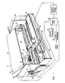
- the inkjet printer 10 (FIG. 1) has the reciprocable print head carriage 11 which receives the disposable print head 12.
- the frame of the ink jet printer consists of a pair of boards 13, 14 which are held apart by a pair of rods 15.
- the print head carriage 11 is guided by means of the guide rod 16 projecting through the opening 17 and is connected with its nut 19 to the threaded spindle 18.
- the rod 20 serves to support and guide the print head carriage 11 at its other end.
- the motor 21 shown in broken lines is partially encapsulated in the cylinder 22, in the wall of which there are openings 23. These openings are arranged between annular beads on which the paper to be labeled rests.
- the radial disks 24 of the cylinder 22 are connected to the output shaft 25 of the engine. The right end of this shaft is mounted in a bearing arranged in the board 14 and not shown.
- a portion of the circuit board 14 is cut out in alignment with the end of the cylinder 22 to provide an opening communicating with the cylinder interior.
- a fan is attached to the motor 26, which serves to evacuate the interior of the cylinder, thereby pulling the paper 27 to be printed onto the outer surface of the cylinder.
- the timing disk 35 is sensed by the transmitter 36 to produce a series of output pulses which serve as timing signals for the operation of the drop generator in the disposable print head 12, as described below.
- the motor 21 rotates
- the threaded spindle 18 also rotates. Since the latter is in operative connection with the nut 19, the print head carriage 11 sweeps over the moving paper 27 to be printed on at a speed which is determined by the pitch of the threaded spindle 18 and the transmission ratio the rollers 30, 32.
- the lever 39 is arranged below the print head carriage 11 in order to disengage the nut 19, which acts as an openable lock, from the threaded spindle 18 and to allow the print head carriage 11 to move freely along the guide rods 16, 20.
- the plate 40 with the edge guides 41 is provided.
- the paper is removable by stopping the motor 21 or by means of the air hole 42 on the vacuum pump 26, which serves to reduce the negative pressure inside the cylinder.
- the roller pairs 30, 32 and 31, 33 give different gear ratios to change the print density on the paper by changing the speed at which the print head carriage 11 crosses the paper on the cylinder.
- Control signals for the ejection of droplets from the disposable print head 12 are supplied via conductors in the flat cable 44 from the character generator 45 and the print line buffer 46 via the control logic 47.
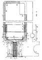
- the disposable print head 12 is shown in more detail in FIG. 2 and has the housing parts 50 and 51, which together form a unitary cartridge, which acts as a bottle.
- the housing is preferably made of a plastic.
- the housing part 50 has the neck 52 with the inner flange 53 and the outer flange 54 in order to store the disposable print head in the receiving device 55 of the print head carriage 11 in its longitudinal direction in a determined manner.
- the tube 57 is inserted from a piezoelectric material which, when excited, acts as a drop generator to eject droplets of ink.
- the tube has an inner conductive plating 58 that extends continuously to the rear edge to connect to the band 59 on the outer surface of the tube.
- the nozzle plate 60 having a nozzle opening 61 is fixed to the left end of the tube 57 to provide an opening for ejecting the ink droplets.
- the outer surface of the tube 57 is also almost completely covered with an electrically conductive material 62, but is insulated from the band 59.
- the tube is supported in the housing on a pair of electrically conductive compliant rings 63, 64 which are spaced apart by the non-conductive plastic tube 65.
- the interior of the housing opening 56 has a pair of electrically conductive bands 67, 68 which are connected to corresponding rings 63, 64.
- the bands 67, 68 on the surface of the opening 56 are also provided with conductors 69, connected '70 which bridge the wall of the neck 52 and communicate with outer conductive Ringbähdern 71, 72 on the neck 52 in connection. These tapes are in contact with similar semicircular tapes 73, 74 on the inner surface of the cradle 55.
- the semicircular tapes 73, 74 are connected to conductors within the flat cable 44 (FIG. 1). Signals from the conductors in the flat cable 44 are thus capable of selectively energizing the piezoelectric tube 57 to cause sufficient contraction for the purpose of ejecting ink droplets from the nozzle opening 61 against the paper to be printed.
- the ink in the disposable printhead 12 is in the bladder 80 in the housing portion 51.
- a suitable bladder material for aqueous ink is that commonly used for finger covers or the like.
- the ring 82 is pressed into the interior of the housing part 51 to hold the bladder 80 in place and the open end of the bladder is retracted over the reduced diameter 81 of the housing part 51 along its outside.
- the housing part 50 is connected to the housing part 51, as shown, and separates the edge of the bladder between the reduced diameter part 81 and the outer edge 83.
- a lubricant which is insoluble in the ink helps in the aforementioned combination of the two housing parts and seals at the same time from.
- the filter 84 In order to avoid contamination of the nozzle opening 61, the ink coming from the bubble is cleaned in the filter 84, which is held in position by the ring 85.
- a disc of filter material can form a finely perforated membrane.
- the bolt 86 which is inserted into the housing, serves to cooperate with a recess 67 in the print head carriage.
- the disposable print head is carried at the rear end of the print head carriage 11 by the concave receiving bearing 88, which is similar to the receiving device 55 at the front of the print head carriage 11.
- the air hole 89 is provided which connects the inside of the disposable print head 12 to the outside air pressure. Ejecting ink creates a slight negative pressure inside the bubble, causing it to collapse.
- the disposable print head is held in the receiving devices of the print head carriage 11 and electrical signals are supplied via the conductors in the flat cable 44.
- This causes the squeeze tube to contract, resulting in the generation of successive ink droplets that are ejected against the paper to be printed.
- the vacuum cylinder carrying the paper to be printed 27 rotates, the printhead crosses the paper to form characters by successive rows of optionally created droplets.
- This one-way pressure head results in an inexpensive, containing moiety drop generator, filters and ink supply can be the wor wegge- after the consumption of the ink f s. This concept enables the exchange of nozzles of different sizes and inks of different colors and compositions.
- the disposable print head can be modified by adding nozzles to enable faster printing or a different dot density. It may also be desirable to provide additional nozzles in a single, disposable printhead and to feed each nozzle with different color ink for optional color printing. 3 allows printing with two different colors. However, the nozzle and tube assembly within the neck of the disposable printhead can be used with a single bubble or color of ink, rather than the two bubbles shown. The reference numerals of the elements of the second nozzle have been provided with the suffix "a".
- the disposable print head 100 (Fig. 3) contains two piezoelectric tubes 57 and 57a, which have a similar structure and elastic rings 63, 63a, 64 and 64a.
- a base electrode 70a is provided which is connected to the ring-shaped conductor 72, like the conductor 70.
- individual control circuits require special rings 71 and 71a and conductors 66 and 66a.
- Each drop generator 56 and 56a is connected to its ink supply by a channel 103 or 104, respectively.
- Each of these channels also connects the chamber 105 in which the filter 106 is held by the locking ring 107.
- Ink is supplied through the filters from the bubbles 108 connected to the chamber 109.
- Each of the bubbles is held in place by squeezing the open end of the bubble into the recess 110 and then pinching the edge of the bubble using the elastic ring 111.
- the air hole 112 allows the bubbles to collapse after the ink is used up.
- Each bladder chamber 108 and 109 cooperates with a special filling opening 113, which are closed by plugs 114 after filling.
- a plurality of nozzles can be arranged horizontally or in different planes.
- the disposable print head 12 and the holding device 55 are shown in more detail in FIG. 4.
- the receptacle 55 has a substantially semicircular shape to match the neck 52 of the disposable printhead so that reliable electrical contacts are maintained between cooperating ring conductor tapes 71 and semicircular tapes 73.
- the radii of the receiving device and ribbons 73 are slightly smaller than those of the ribbons 71, which results in a tight fit after the disposable print head has been inserted.
- the cradle legs 55a extend a little beyond the end points of a horizontal through the center of the neck.
- the cradle portion or the entire print carriage 11 is preferably molded from a plastic, such as nylon or the like, which has a certain amount of flexibility so that it can be spread when the disposable print head is inserted.
- a plastic such as nylon or the like
- the slot 55b can be cut laterally into the receptacle to allow easier deflection of the legs.
- Vertical slots 55c are also provided to form separate support fingers for one end of each semicircular band 73. This arrangement allows the bands 73 to be individually deflected to accommodate changes in the dimensions of the neck and ring bands 71.
Landscapes
- Physics & Mathematics (AREA)
- General Physics & Mathematics (AREA)
- Ink Jet (AREA)
- Particle Formation And Scattering Control In Inkjet Printers (AREA)
Applications Claiming Priority (2)
| Application Number | Priority Date | Filing Date | Title |
|---|---|---|---|
| US218145 | 1980-12-19 | ||
| US06/218,145 US4329698A (en) | 1980-12-19 | 1980-12-19 | Disposable cartridge for ink drop printer |
Publications (3)
| Publication Number | Publication Date |
|---|---|
| EP0054694A2 EP0054694A2 (de) | 1982-06-30 |
| EP0054694A3 EP0054694A3 (en) | 1983-08-03 |
| EP0054694B1 true EP0054694B1 (de) | 1986-05-28 |
Family
ID=22813939
Family Applications (1)
| Application Number | Title | Priority Date | Filing Date |
|---|---|---|---|
| EP81108977A Expired EP0054694B1 (de) | 1980-12-19 | 1981-10-27 | Für einen Tintenstrahldrucker mit einem entlang der Druckzeile hin und her bewegbaren Druckwagen bestimmter Druckkopf |
Country Status (4)
| Country | Link |
|---|---|
| US (1) | US4329698A (enExample) |
| EP (1) | EP0054694B1 (enExample) |
| JP (2) | JPS57110459A (enExample) |
| DE (1) | DE3174728D1 (enExample) |
Families Citing this family (75)
| Publication number | Priority date | Publication date | Assignee | Title |
|---|---|---|---|---|
| IT1145242B (it) * | 1981-12-23 | 1986-11-05 | Olivetti & Co Spa | Testina di stampa a getto d inchiostro e relativa stampante seriale |
| JPS58138656A (ja) * | 1982-02-12 | 1983-08-17 | Canon Inc | 記録装置 |
| JPS58140886A (ja) * | 1982-02-17 | 1983-08-20 | Canon Inc | 記録装置 |
| JPS58194550A (ja) * | 1982-05-10 | 1983-11-12 | Canon Inc | インクカセット |
| JPS58194549A (ja) * | 1982-05-10 | 1983-11-12 | Canon Inc | インクジェット装置 |
| US5216452A (en) * | 1982-05-10 | 1993-06-01 | Canon Kabushiki Kaisha | Ink storing device |
| US4412233A (en) * | 1982-06-07 | 1983-10-25 | Ncr Corporation | Ink evaporation prevention means for ink jet print head |
| US4500895A (en) * | 1983-05-02 | 1985-02-19 | Hewlett-Packard Company | Disposable ink jet head |
| US5328279A (en) | 1984-05-22 | 1994-07-12 | Seiko Epson Corporation | Dot matrix printer head |
| DE3342894A1 (de) * | 1983-11-26 | 1985-06-05 | Olympia Werke Ag, 2940 Wilhelmshaven | Kassette fuer einen schreibkopf einer tintenschreibvorrichtung in einer schreibmaschine |
| JPH0679853B2 (ja) * | 1983-12-09 | 1994-10-12 | キヤノン株式会社 | 液体噴射装置 |
| IT1160247B (it) * | 1983-12-27 | 1987-03-04 | Olivetti & Co Spa | Testina di stampa seriale a getto d'inchiostro elettricamente conduttivo |
| JPH0626886B2 (ja) * | 1984-01-30 | 1994-04-13 | キヤノン株式会社 | 液体噴射記録装置 |
| JPS60204347A (ja) * | 1984-03-30 | 1985-10-15 | Canon Inc | インクジエツト記録ヘツドの保存方法 |
| US4635080A (en) * | 1984-03-30 | 1987-01-06 | Canon Kabushiki Kaisha | Liquid injection recording apparatus |
| US4630078A (en) * | 1984-03-30 | 1986-12-16 | Canon Kabushiki Kaisha | Liquid recording head |
| JPH064324B2 (ja) * | 1984-06-11 | 1994-01-19 | キヤノン株式会社 | 液体噴射記録ヘツド |
| JPS6135955A (ja) * | 1984-07-30 | 1986-02-20 | Canon Inc | 液体噴射記録ヘツド |
| IT1179109B (it) * | 1984-09-10 | 1987-09-16 | Olivetti & Co Spa | Testina di stampa seriale a getto d'inchiostro |
| JPH069920B2 (ja) * | 1985-02-28 | 1994-02-09 | キヤノン株式会社 | インクジエツト記録装置 |
| US5025271A (en) * | 1986-07-01 | 1991-06-18 | Hewlett-Packard Company | Thin film resistor type thermal ink pen using a form storage ink supply |
| US4803500A (en) * | 1986-07-04 | 1989-02-07 | Siemens Aktiengesellschaft | Ink printer means comprising interchangeable ink heads |
| US4734717A (en) * | 1986-12-22 | 1988-03-29 | Eastman Kodak Company | Insertable, multi-array print/cartridge |
| US4755836A (en) * | 1987-05-05 | 1988-07-05 | Hewlett-Packard Company | Printhead cartridge and carriage assembly |
| JP2785031B2 (ja) * | 1988-03-02 | 1998-08-13 | キヤノン株式会社 | シリアルプリンタ |
| US4929969A (en) * | 1989-08-25 | 1990-05-29 | Eastman Kodak Company | Ink supply construction and printing method for drop-on-demand ink jet printing |
| CA2025560C (en) * | 1989-09-18 | 1995-07-18 | Seiichiro Karita | Ink jet recording head and ink jet recording apparatus having same |
| US5121132A (en) * | 1989-09-29 | 1992-06-09 | Hewlett-Packard Company | Ink delivery system for printers |
| US5461405A (en) * | 1989-10-30 | 1995-10-24 | Eastman Kodak Company | Ink jet printer device with exchangeable printheads |
| EP0560562B1 (en) * | 1992-03-09 | 1999-07-07 | Canon Kabushiki Kaisha | Multi recording system using monochrome printer |
| US5475403A (en) * | 1992-11-25 | 1995-12-12 | Personal Electronic Products, Inc. | Electronic checking with printing |
| DE69418767T2 (de) * | 1993-04-30 | 1999-10-07 | Hewlett-Packard Co., Palo Alto | Gemeinsame Farbkassettenplattform für verschiedene Druckköpfe |
| US5477255A (en) * | 1993-09-07 | 1995-12-19 | Hewlett Packard Corporation | Ink cartridge system with improved volumetric capacity and method for using the same |
| US5537136A (en) * | 1993-12-07 | 1996-07-16 | Lexmark International, Inc. | Ink jet cartridge including filter inserts |
| US6196669B1 (en) | 1994-10-31 | 2001-03-06 | Hewlett-Packard Company | High durability pressure control bladder for use in an ink delivery system |
| US5680164A (en) * | 1994-11-29 | 1997-10-21 | Hewlett-Packard Company | Refill method and apparatus for ink cartridge units |
| US5642144A (en) * | 1994-11-29 | 1997-06-24 | Hewlett-Packard Company | Rechargeable pen for printer |
| AU7502996A (en) * | 1995-11-08 | 1997-05-29 | American Ink Jet Corporation | Refilling ink jet cartridges |
| US5847734A (en) * | 1995-12-04 | 1998-12-08 | Pawlowski, Jr.; Norman E. | Air purge system for an ink-jet printer |
| US5815182A (en) * | 1995-12-04 | 1998-09-29 | Hewlett-Packard Company | Fluid interconnect for ink-jet pen |
| US5900895A (en) * | 1995-12-04 | 1999-05-04 | Hewlett-Packard Company | Method for refilling an ink supply for an ink-jet printer |
| US5732751A (en) * | 1995-12-04 | 1998-03-31 | Hewlett-Packard Company | Filling ink supply containers |
| US5771053A (en) * | 1995-12-04 | 1998-06-23 | Hewlett-Packard Company | Assembly for controlling ink release from a container |
| US5700315A (en) * | 1996-02-29 | 1997-12-23 | Hewlett-Packard Company | Anti-outgassing ink composition and method for using the same |
| US6071368A (en) * | 1997-01-24 | 2000-06-06 | Hewlett-Packard Co. | Method and apparatus for applying a stable printed image onto a fabric substrate |
| US6090749A (en) * | 1997-03-31 | 2000-07-18 | Hewlett-Packard Company | Method for applying clear, vivid, and water-fast printed images to a susbtrate |
| US6045215A (en) * | 1997-08-28 | 2000-04-04 | Hewlett-Packard Company | High durability ink cartridge printhead and method for making the same |
| US6062679A (en) * | 1997-08-28 | 2000-05-16 | Hewlett-Packard Company | Printhead for an inkjet cartridge and method for producing the same |
| US6155675A (en) * | 1997-08-28 | 2000-12-05 | Hewlett-Packard Company | Printhead structure and method for producing the same |
| US6155676A (en) * | 1997-10-16 | 2000-12-05 | Hewlett-Packard Company | High-durability rhodium-containing ink cartridge printhead and method for making the same |
| US6179413B1 (en) | 1997-10-31 | 2001-01-30 | Hewlett-Packard Company | High durability polymide-containing printhead system and method for making the same |
| US6012807A (en) * | 1998-03-06 | 2000-01-11 | Hewlett-Packard Company | Ink containment unit for use in an ink delivery system |
| US6082854A (en) * | 1998-03-16 | 2000-07-04 | Hewlett-Packard Company | Modular ink-jet hard copy apparatus and methodology |
| JP4321738B2 (ja) | 1998-06-24 | 2009-08-26 | チェン アンド チェン エルエルシー | 液体試料試験システム |
| US7799521B2 (en) * | 1998-06-24 | 2010-09-21 | Chen & Chen, Llc | Thermal cycling |
| US6780617B2 (en) | 2000-12-29 | 2004-08-24 | Chen & Chen, Llc | Sample processing device and method |
| US6149719A (en) | 1998-10-28 | 2000-11-21 | Hewlett-Packard Company | Light sensitive invisible ink compositions and methods for using the same |
| US6241349B1 (en) | 1999-01-28 | 2001-06-05 | Hewlett-Packard Company | High-durability ink containment unit for use in an ink delivery system |
| US6347861B1 (en) | 1999-03-02 | 2002-02-19 | Hewlett-Packard Company | Fluid ejection device having mechanical intercoupling structure embedded within chamber layer |
| US6290331B1 (en) | 1999-09-09 | 2001-09-18 | Hewlett-Packard Company | High efficiency orifice plate structure and printhead using the same |
| US6130688A (en) * | 1999-09-09 | 2000-10-10 | Hewlett-Packard Company | High efficiency orifice plate structure and printhead using the same |
| US6599593B1 (en) | 2000-09-14 | 2003-07-29 | Hewlett-Packard Development Company, L.P. | High efficiency print media products and methods for producing the same |
| US6528148B2 (en) | 2001-02-06 | 2003-03-04 | Hewlett-Packard Company | Print media products for generating high quality visual images and methods for producing the same |
| JP4513085B2 (ja) | 2001-09-11 | 2010-07-28 | アイキューム インク | 試料の容器 |
| US6871942B2 (en) * | 2002-04-15 | 2005-03-29 | Timothy R. Emery | Bonding structure and method of making |
| US6689433B2 (en) | 2002-05-06 | 2004-02-10 | Hewlett-Packard Development Company, L.P. | Print media products for generating high quality images and methods for making the same |
| WO2004080597A2 (en) | 2003-02-05 | 2004-09-23 | Iquum, Inc. | Sample processing tubule |
| US7448734B2 (en) * | 2004-01-21 | 2008-11-11 | Silverbrook Research Pty Ltd | Inkjet printer cartridge with pagewidth printhead |
| US7095892B2 (en) * | 2005-01-26 | 2006-08-22 | Motorola, Inc. | Object-of-interest image capture |
| WO2019209374A1 (en) | 2018-04-24 | 2019-10-31 | Hewlett-Packard Development Company, L.P. | Sequenced droplet ejection to deliver fluids |
| US11925932B2 (en) | 2018-04-24 | 2024-03-12 | Hewlett-Packard Development Company, L.P. | Microfluidic devices |
| WO2020018075A1 (en) * | 2018-07-17 | 2020-01-23 | Hewlett-Packard Development Company, L.P. | Droplet ejectors to mix fluids |
| US11547993B2 (en) | 2018-07-17 | 2023-01-10 | Hewlett-Packard Development Company, L.P. | Droplet ejectors with target media |
| US11325380B2 (en) | 2018-07-17 | 2022-05-10 | Hewlett-Packard Development Company, L.P. | Droplet ejectors to provide fluids to droplet ejectors |
| US11274778B2 (en) * | 2018-12-12 | 2022-03-15 | International Business Machines Corporation | Couplings with engagement monitor |
Family Cites Families (14)
| Publication number | Priority date | Publication date | Assignee | Title |
|---|---|---|---|---|
| BE787962A (fr) * | 1971-08-24 | 1973-02-26 | Siemens Ag | Dispositif enregistreur pour imprimeuse a jet d'encre |
| US3787884A (en) * | 1973-01-08 | 1974-01-22 | Ibm | Ink jet printer |
| US3823409A (en) * | 1973-01-30 | 1974-07-09 | Rca Corp | Rotatable paraboloidal reservoir useful in an ink jet printer |
| DE2543452C3 (de) * | 1975-09-29 | 1980-06-12 | Siemens Ag, 1000 Berlin Und 8000 Muenchen | Entlüftungsvorrichtung für Tintenversorgungssysteme von Tintenstrahlschreibeinrichtungen |
| US4183031A (en) * | 1976-06-07 | 1980-01-08 | Silonics, Inc. | Ink supply system |
| JPS5932313B2 (ja) * | 1976-06-07 | 1984-08-08 | コニカ株式会社 | インクジエツト記録装置のインク通路洗浄方法 |
| US4032928A (en) * | 1976-08-12 | 1977-06-28 | Recognition Equipment Incorporated | Wideband ink jet modulator |
| JPS5542875A (en) * | 1978-09-21 | 1980-03-26 | Canon Inc | Recording head cartridge |
| JPS55101472A (en) * | 1979-01-31 | 1980-08-02 | Canon Inc | Liquid jet recording device |
| JPS55126461A (en) * | 1979-03-26 | 1980-09-30 | Canon Inc | Cartridge-type recording head |
| JPS55150372A (en) * | 1979-05-11 | 1980-11-22 | Seiko Epson Corp | Printer |
| JPS55150376A (en) * | 1979-05-14 | 1980-11-22 | Canon Inc | Liquid ejection recording head |
| JPS55156072A (en) * | 1979-05-23 | 1980-12-04 | Ricoh Co Ltd | Multinozzle head in ink jet recording device |
| JPS55161667A (en) * | 1979-06-05 | 1980-12-16 | Seiko Epson Corp | Ink jet recorder |
-
1980
- 1980-12-19 US US06/218,145 patent/US4329698A/en not_active Expired - Fee Related
-
1981
- 1981-10-01 JP JP56154910A patent/JPS57110459A/ja active Granted
- 1981-10-27 DE DE8181108977T patent/DE3174728D1/de not_active Expired
- 1981-10-27 EP EP81108977A patent/EP0054694B1/de not_active Expired
- 1981-11-20 JP JP56185625A patent/JPS57188368A/ja active Granted
Also Published As
| Publication number | Publication date |
|---|---|
| JPH0260513B2 (enExample) | 1990-12-17 |
| JPS6367475B2 (enExample) | 1988-12-26 |
| EP0054694A3 (en) | 1983-08-03 |
| EP0054694A2 (de) | 1982-06-30 |
| JPS57110459A (en) | 1982-07-09 |
| US4329698A (en) | 1982-05-11 |
| DE3174728D1 (en) | 1986-07-03 |
| JPS57188368A (en) | 1982-11-19 |
Similar Documents
| Publication | Publication Date | Title |
|---|---|---|
| EP0054694B1 (de) | Für einen Tintenstrahldrucker mit einem entlang der Druckzeile hin und her bewegbaren Druckwagen bestimmter Druckkopf | |
| DE3316970C2 (enExample) | ||
| DE3316474C2 (enExample) | ||
| DE69013419T2 (de) | Thermischer Tintenstrahl-Druckkopf. | |
| DE3645079C2 (enExample) | ||
| DE3780550T2 (de) | Tintenversorgungssysteme. | |
| DE69311285T2 (de) | Haltevorrichtung für Kassetten an einem Tintenstrahldrucker und Vorrichtung zum Aufrechterhalten des Tintenniveaus in den Kassetten | |
| DE60301603T2 (de) | Wartungsverfahren für einen Tintenstrahldruckkopf | |
| DE60300337T2 (de) | Tintenbehälter, Aufzeichnungskopf und Aufzeichnungsgerät mit einem solchen Behälter | |
| DE69309413T2 (de) | Tintennachfüllvorrichtung, Aufzeichnungsgerät mit dieser und Tintennachfüllverfahren | |
| DE19534577C2 (de) | Tintenpatrone und Tintenstrahl-Aufzeichnungsgerät | |
| DE69026036T2 (de) | Farbstrahlaufzeichnungsvorrichtung | |
| DE69503102T2 (de) | Venturi-Entladungssystem zur Beherrschung des Tintenstrahl-Aerosols | |
| EP0137313B1 (de) | Vorrichtung für Tintenschreibeinrichtungen zum Beschreiben eines Aufzeichnungsträgers | |
| DE69213535T2 (de) | Antriebsvorrichtung und Verfahren für einen Vielfarben-Tintenstrahlschreiber | |
| DE60301047T2 (de) | Schutzkappenanordnung mit eingebautem Wischer | |
| DE69113740T2 (de) | Tintenstrahldruckgerät. | |
| DE69502980T2 (de) | Abdeckverfahren für Farbstrahlaufzeichnungsvorrichtung | |
| DE3401071A1 (de) | Vorrichtung zum nachfuellen von tintenbehaeltern in tintenschreibeinrichtungen | |
| DE69512578T2 (de) | Tintenstahlaufzeichnungsgerät, Reinigungsverfahren und Informationsverarbeitungssystem dafür | |
| DE69935395T2 (de) | Selbstreinigender tintenstrahldrucker mit strömungsrichtungsumkehrung und verfahren zum zusammenbauen des druckers | |
| DE3039165A1 (de) | Tintenstrahlschreiber | |
| DE2925812A1 (de) | Tintendruckeinrichtung zum mehrfarbigen bedrucken eines aufzeichnungstraegers | |
| DE69319319T2 (de) | Verfahren und Gerät zur Entfernung von Abfallfarbe in einer Dichtstation | |
| DE60101876T2 (de) | Kopfreinigungsvorrichtung, Kopfreinigungsverfahren und Tintenstrahlaufzeichnungsgerät |
Legal Events
| Date | Code | Title | Description |
|---|---|---|---|
| PUAI | Public reference made under article 153(3) epc to a published international application that has entered the european phase |
Free format text: ORIGINAL CODE: 0009012 |
|
| 17P | Request for examination filed |
Effective date: 19811027 |
|
| AK | Designated contracting states |
Designated state(s): DE FR GB IT |
|
| PUAL | Search report despatched |
Free format text: ORIGINAL CODE: 0009013 |
|
| AK | Designated contracting states |
Designated state(s): DE FR GB IT |
|
| GRAA | (expected) grant |
Free format text: ORIGINAL CODE: 0009210 |
|
| AK | Designated contracting states |
Kind code of ref document: B1 Designated state(s): DE FR GB IT |
|
| ITF | It: translation for a ep patent filed | ||
| REF | Corresponds to: |
Ref document number: 3174728 Country of ref document: DE Date of ref document: 19860703 |
|
| ET | Fr: translation filed | ||
| R20 | Corrections of a patent specification |
Effective date: 19860716 |
|
| PLBE | No opposition filed within time limit |
Free format text: ORIGINAL CODE: 0009261 |
|
| STAA | Information on the status of an ep patent application or granted ep patent |
Free format text: STATUS: NO OPPOSITION FILED WITHIN TIME LIMIT |
|
| 26N | No opposition filed | ||
| PG25 | Lapsed in a contracting state [announced via postgrant information from national office to epo] |
Ref country code: GB Effective date: 19891027 |
|
| GBPC | Gb: european patent ceased through non-payment of renewal fee | ||
| PG25 | Lapsed in a contracting state [announced via postgrant information from national office to epo] |
Ref country code: FR Effective date: 19900629 |
|
| PG25 | Lapsed in a contracting state [announced via postgrant information from national office to epo] |
Ref country code: DE Effective date: 19900703 |
|
| REG | Reference to a national code |
Ref country code: FR Ref legal event code: ST |