EP0053677A1 - Analyseur de gaz par infrarouge non dispersif - Google Patents
Analyseur de gaz par infrarouge non dispersif Download PDFInfo
- Publication number
- EP0053677A1 EP0053677A1 EP81108432A EP81108432A EP0053677A1 EP 0053677 A1 EP0053677 A1 EP 0053677A1 EP 81108432 A EP81108432 A EP 81108432A EP 81108432 A EP81108432 A EP 81108432A EP 0053677 A1 EP0053677 A1 EP 0053677A1
- Authority
- EP
- European Patent Office
- Prior art keywords
- radiation
- beam paths
- gas
- absorption
- receiving chambers
- Prior art date
- Legal status (The legal status is an assumption and is not a legal conclusion. Google has not performed a legal analysis and makes no representation as to the accuracy of the status listed.)
- Granted
Links
- 230000005855 radiation Effects 0.000 claims abstract description 23
- 238000010521 absorption reaction Methods 0.000 claims abstract description 14
- 230000001419 dependent effect Effects 0.000 claims abstract description 3
- 239000000203 mixture Substances 0.000 claims description 3
- 238000001914 filtration Methods 0.000 abstract description 2
- 238000005259 measurement Methods 0.000 description 7
- 230000003287 optical effect Effects 0.000 description 4
- 230000002093 peripheral effect Effects 0.000 description 2
- 230000010363 phase shift Effects 0.000 description 2
- 230000000694 effects Effects 0.000 description 1
- 238000010438 heat treatment Methods 0.000 description 1
- 238000004519 manufacturing process Methods 0.000 description 1
- 108090000623 proteins and genes Proteins 0.000 description 1
- 230000035945 sensitivity Effects 0.000 description 1
Images
Classifications
-
- G—PHYSICS
- G01—MEASURING; TESTING
- G01N—INVESTIGATING OR ANALYSING MATERIALS BY DETERMINING THEIR CHEMICAL OR PHYSICAL PROPERTIES
- G01N21/00—Investigating or analysing materials by the use of optical means, i.e. using sub-millimetre waves, infrared, visible or ultraviolet light
- G01N21/17—Systems in which incident light is modified in accordance with the properties of the material investigated
- G01N21/25—Colour; Spectral properties, i.e. comparison of effect of material on the light at two or more different wavelengths or wavelength bands
- G01N21/31—Investigating relative effect of material at wavelengths characteristic of specific elements or molecules, e.g. atomic absorption spectrometry
- G01N21/35—Investigating relative effect of material at wavelengths characteristic of specific elements or molecules, e.g. atomic absorption spectrometry using infrared light
- G01N21/37—Investigating relative effect of material at wavelengths characteristic of specific elements or molecules, e.g. atomic absorption spectrometry using infrared light using pneumatic detection
Definitions
- the invention relates to a non-dispersive infrared (NDIR) gas analyzer for measuring at least one component of a sample gas consisting of a gas mixture, with two parallel beam paths, through which periodically interrupted infrared radiation passes, with a sample gas flowing through it in both beam paths Measuring cuvette, with means for zero point adjustment by changing the radiation energies in the beam paths, with one receiver chamber containing the measuring component or a gas corresponding to its absorption in each beam path, with means for selectively influencing the radiation entering the receiver chambers and with means for converting the absorption-dependent differential pressure between the receiver chambers into an electrical signal.
- NDIR non-dispersive infrared
- the means for selectively influencing the radiation entering the receiver chambers generally consist of an optical gas filter, i.e. a gas enclosed in a radiation-permeable chamber, its Main absorption band corresponds to that of the measuring component in the sample gas.
- This so-called selectivation filter is arranged in one of the beam paths in front of the receiver chamber.
- the concentration of the gas filling in the optical gas filter is chosen so high that part of the energy, especially in the center of an absorption band, is absorbed before entering the receiver chamber.
- a disadvantage of optical with the use gas filter is the relatively large developmental and expenditure on equipment in the production and provision de: in length and filling different gas filter for measuring components in question.
- Another disadvantage of known devices is the phase shift in the asymmetry of the gas volumes in the two beam paths when the measurement signals are formed.
- a solution to the problem is that the rear end faces in Stra direction of the same dimensions gene receiving chambers are designed as radiation-permeable windows and that behind one of the windows part of the radiation emitted in corresponding receiver chamber reflecting means are arranged.
- the optical gas filter can be omitted.
- the reflected portion which amplifies the influence of the band edge radiation, can be set so that between the Em; trap chambers a usable difference signal auftri which speaks ent the proportion of the measuring component in the sample gas ent.
- the gas volumes in both beam paths, especially in the receiver chambers, can be strictly symmetrical in each Fa with regard to their absorption lengths, so that a phase shift and the resulting interference signal does not occur.
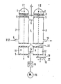
- the design principle of a two-beam NDIR gas analyzer is shown in the figure and described below.
- the radiation emanating from two infrared radiation sources 1 and 2 is bundled and, periodically interrupted by the peripheral aperture 3, enters two parallel beam paths I and II.
- a measuring cell 4 which consists of two parallel hollow cylinders 7 and 8, which are provided with radiation-permeable windows 5 on their end faces and are connected to one another in terms of flow, has a gas inlet 9 into the hollow cylinder 7 and a gas outlet 10 from the hollow cylinder 8 .
- a sample gas consisting of the gas components X, Y, Z flows through the measuring cell 4.
- the measuring cuvette 4 is followed in each beam path by a receiver chamber 11, 12 with the same dimensions, which is provided with radiation-permeable windows 5 on its front and rear end faces. If, for example, the proportion of component X in the sample gas, that is to say the measurement component, is to be determined, the receiver chambers are filled with a gas or gas mixture which contains the measurement component or has their IR absorption bands.
- the two same receiver chambers 11 and 12 are connected via a line 13 which contains a flow sensor 14 which operates according to the principle of a thermal anemometer and which, as a measurement sensor of a transmitter 15, emits an electrical signal for the display 16.
- a flat plate 19 provided with a reflecting layer 18, e.g. B. a mirror, relative to the central axis of the beam path II axially and / or radially displaceable or tiltable about an axis lying in a plane parallel to the exit window 5 of the receiver chamber 12.
- An adjustable screen can also be provided between the exit window and the fixed mirror.
- a non-IR-absorbing gas is passed through the measuring cell 4 to set the zero point.
- modulated radiation is absorbed into the receiver chambers 11 and 12 filled with a gas corresponding to the measuring component X, the band center radiation of the main absorption band being more strongly absorbed than the band edge radiation which the receiver chambers receive from the rear Leaves window 5 again.
- Part of the band edge radiation emerging from the receiver chamber 12 wants to be radiated back again with the aid of the reflecting means 17, so that both band center and band edge radiation are absorbed in the receiver chamber 12 in the beam path II, and band center radiation is mainly absorbed in the receiver chamber 11 in the beam path I, which results in different Heating, pressure rise and a compensation flow corresponding to the differential pressure. leads over line 13.
- a certain value for the band edge sensitivity can be set by adjusting the reflecting means 17 and thus changing the reflected portion of the band edge radiation and so reduce cross-sensitivity.
Landscapes
- Physics & Mathematics (AREA)
- Spectroscopy & Molecular Physics (AREA)
- Health & Medical Sciences (AREA)
- Life Sciences & Earth Sciences (AREA)
- Chemical & Material Sciences (AREA)
- Analytical Chemistry (AREA)
- Biochemistry (AREA)
- General Health & Medical Sciences (AREA)
- General Physics & Mathematics (AREA)
- Immunology (AREA)
- Pathology (AREA)
- Investigating Or Analysing Materials By Optical Means (AREA)
Applications Claiming Priority (2)
| Application Number | Priority Date | Filing Date | Title |
|---|---|---|---|
| DE3046234 | 1980-12-08 | ||
| DE19803046234 DE3046234A1 (de) | 1980-12-08 | 1980-12-08 | Nichtdispersiver infrarot-gasanalysator |
Publications (2)
| Publication Number | Publication Date |
|---|---|
| EP0053677A1 true EP0053677A1 (fr) | 1982-06-16 |
| EP0053677B1 EP0053677B1 (fr) | 1987-01-07 |
Family
ID=6118628
Family Applications (1)
| Application Number | Title | Priority Date | Filing Date |
|---|---|---|---|
| EP81108432A Expired EP0053677B1 (fr) | 1980-12-08 | 1981-10-16 | Analyseur de gaz par infrarouge non dispersif |
Country Status (2)
| Country | Link |
|---|---|
| EP (1) | EP0053677B1 (fr) |
| DE (2) | DE3046234A1 (fr) |
Cited By (2)
| Publication number | Priority date | Publication date | Assignee | Title |
|---|---|---|---|---|
| US7268882B2 (en) * | 2004-02-18 | 2007-09-11 | Tyco Electronics Raychem Gmbh | Gas sensor arrangement in an integrated construction |
| DE102012216210A1 (de) | 2012-09-12 | 2014-01-30 | Siemens Aktiengesellschaft | Nichtdispersiver Infrarot-Gasanalysator nach dem Zweistrahlverfahren |
Families Citing this family (2)
| Publication number | Priority date | Publication date | Assignee | Title |
|---|---|---|---|---|
| DE3321360A1 (de) * | 1983-06-14 | 1984-12-20 | Hartmann & Braun Ag, 6000 Frankfurt | Nichtdispersiver infrarot-gasanalysator |
| DE3842399C2 (de) * | 1988-12-16 | 1997-07-31 | Fisher Rosemount Gmbh & Co Ges | Mikroströmungsfühler für Gase |
Citations (1)
| Publication number | Priority date | Publication date | Assignee | Title |
|---|---|---|---|---|
| DE2639210A1 (de) * | 1976-08-31 | 1978-03-02 | Siemens Ag | Einrichtung zur nullpunkt-einstellung bei nichtdispersiven infrarot-gasanalysatoren mit doppelschicht-empfaengerkammern |
Family Cites Families (2)
| Publication number | Priority date | Publication date | Assignee | Title |
|---|---|---|---|---|
| DE2333664C3 (de) * | 1973-07-02 | 1979-11-29 | H. Maihak Ag, 2000 Hamburg | Nichtdispersives Infrarot-Gasanalysengerät |
| DE2405317C2 (de) * | 1974-02-05 | 1982-09-16 | Hartmann & Braun Ag, 6000 Frankfurt | Nichtdispersiver Zweistrahl-Ultrarotabsorptionsgasanalysator |
-
1980
- 1980-12-08 DE DE19803046234 patent/DE3046234A1/de not_active Withdrawn
-
1981
- 1981-10-16 EP EP81108432A patent/EP0053677B1/fr not_active Expired
- 1981-10-16 DE DE8181108432T patent/DE3175813D1/de not_active Expired
Patent Citations (1)
| Publication number | Priority date | Publication date | Assignee | Title |
|---|---|---|---|---|
| DE2639210A1 (de) * | 1976-08-31 | 1978-03-02 | Siemens Ag | Einrichtung zur nullpunkt-einstellung bei nichtdispersiven infrarot-gasanalysatoren mit doppelschicht-empfaengerkammern |
Cited By (2)
| Publication number | Priority date | Publication date | Assignee | Title |
|---|---|---|---|---|
| US7268882B2 (en) * | 2004-02-18 | 2007-09-11 | Tyco Electronics Raychem Gmbh | Gas sensor arrangement in an integrated construction |
| DE102012216210A1 (de) | 2012-09-12 | 2014-01-30 | Siemens Aktiengesellschaft | Nichtdispersiver Infrarot-Gasanalysator nach dem Zweistrahlverfahren |
Also Published As
| Publication number | Publication date |
|---|---|
| DE3175813D1 (de) | 1987-02-12 |
| EP0053677B1 (fr) | 1987-01-07 |
| DE3046234A1 (de) | 1982-07-15 |
Similar Documents
| Publication | Publication Date | Title |
|---|---|---|
| EP0427037B1 (fr) | Analyseur de gaz, non dispersif à rayons infrarouges pour mesurer de façon simultanée la concentration de plusieurs composants d'un échantillon de gaz | |
| DE3811475C2 (fr) | ||
| DE102009025147B3 (de) | Verfahren zum Betrieb eines Spektrometers zur Gasanalyse, sowie Spektrometer selbst | |
| WO2006002740A1 (fr) | Analyseur de gaz a infrarouge non dispersif | |
| DE3139917C2 (fr) | ||
| DE2511771A1 (de) | Beschreibung einer anordnung zum bestimmen des blutalkoholgehaltes ueber die messung der alkoholkonzentration in alveolarer atemluft | |
| DE10351160B3 (de) | Durchfluß-Meßküvette und Transmissionsspektrometer zur Untersuchung biologischer Flüssigkeiten | |
| EP1847827A1 (fr) | Analyseur de gaz à infrarouge non dispersif | |
| DE2359637C2 (de) | Nichtdispersives Ultrarot-Gasanalysengerät | |
| EP0053677A1 (fr) | Analyseur de gaz par infrarouge non dispersif | |
| DE102011108941B4 (de) | Optische Gasanalysatoreinrichtung mit Mitteln zum Verbessern der Selektivität bei Gasgemischanalysen | |
| DE2521453C2 (fr) | ||
| EP0087077A2 (fr) | Dispositif pour la mesure optique de gaz | |
| DE19521362A1 (de) | Messzelle für einen Wasserdampfsensor | |
| WO2017067657A1 (fr) | Dispositif de mesure infrarouge | |
| CH683129A5 (de) | Gasanalysator. | |
| DE2331890C3 (de) | Fourierspektrometer | |
| DE8032658U1 (de) | Nichtdispersiver Infrarot-Gasanalysator | |
| EP1640708A1 (fr) | Analyseur de gaz à deux faisceaux | |
| EP0394870B1 (fr) | Analyseur de gaz à infrarouges non-dispersif | |
| DE3544015A1 (de) | Gasanalysevorrichtung | |
| EP0022246A1 (fr) | Analyseur de gaz à infrarouge non dispersif | |
| DE4116431A1 (de) | Optische messeinrichtung und verfahren zum betreiben der optischen messeinrichtung | |
| DE102011109000B4 (de) | Optische Gasanalysatoreinrichtung mit Mitteln zumVerbessern des Dynamikbereichs der Messung | |
| DE10144808A1 (de) | Vorrichtung zur Analyse einer Gasprobe |
Legal Events
| Date | Code | Title | Description |
|---|---|---|---|
| PUAI | Public reference made under article 153(3) epc to a published international application that has entered the european phase |
Free format text: ORIGINAL CODE: 0009012 |
|
| AK | Designated contracting states |
Designated state(s): DE FR GB NL |
|
| 17P | Request for examination filed |
Effective date: 19830112 |
|
| GRAA | (expected) grant |
Free format text: ORIGINAL CODE: 0009210 |
|
| AK | Designated contracting states |
Kind code of ref document: B1 Designated state(s): DE FR GB NL |
|
| REF | Corresponds to: |
Ref document number: 3175813 Country of ref document: DE Date of ref document: 19870212 |
|
| ET | Fr: translation filed | ||
| PLBE | No opposition filed within time limit |
Free format text: ORIGINAL CODE: 0009261 |
|
| STAA | Information on the status of an ep patent application or granted ep patent |
Free format text: STATUS: NO OPPOSITION FILED WITHIN TIME LIMIT |
|
| 26N | No opposition filed | ||
| PGFP | Annual fee paid to national office [announced via postgrant information from national office to epo] |
Ref country code: GB Payment date: 19910913 Year of fee payment: 11 |
|
| PGFP | Annual fee paid to national office [announced via postgrant information from national office to epo] |
Ref country code: FR Payment date: 19911022 Year of fee payment: 11 |
|
| PGFP | Annual fee paid to national office [announced via postgrant information from national office to epo] |
Ref country code: NL Payment date: 19911031 Year of fee payment: 11 |
|
| PGFP | Annual fee paid to national office [announced via postgrant information from national office to epo] |
Ref country code: DE Payment date: 19911217 Year of fee payment: 11 |
|
| PG25 | Lapsed in a contracting state [announced via postgrant information from national office to epo] |
Ref country code: GB Effective date: 19921016 |
|
| PG25 | Lapsed in a contracting state [announced via postgrant information from national office to epo] |
Ref country code: NL Effective date: 19930501 |
|
| GBPC | Gb: european patent ceased through non-payment of renewal fee |
Effective date: 19921016 |
|
| NLV4 | Nl: lapsed or anulled due to non-payment of the annual fee | ||
| PG25 | Lapsed in a contracting state [announced via postgrant information from national office to epo] |
Ref country code: FR Effective date: 19930630 |
|
| PG25 | Lapsed in a contracting state [announced via postgrant information from national office to epo] |
Ref country code: DE Effective date: 19930701 |
|
| REG | Reference to a national code |
Ref country code: FR Ref legal event code: ST |