EP0052507B1 - Perceuse à percussion - Google Patents
Perceuse à percussion Download PDFInfo
- Publication number
- EP0052507B1 EP0052507B1 EP81305422A EP81305422A EP0052507B1 EP 0052507 B1 EP0052507 B1 EP 0052507B1 EP 81305422 A EP81305422 A EP 81305422A EP 81305422 A EP81305422 A EP 81305422A EP 0052507 B1 EP0052507 B1 EP 0052507B1
- Authority
- EP
- European Patent Office
- Prior art keywords
- ram
- drill
- percussive
- bit
- piston
- Prior art date
- Legal status (The legal status is an assumption and is not a legal conclusion. Google has not performed a legal analysis and makes no representation as to the accuracy of the status listed.)
- Expired
Links
Images

Classifications
-
- B—PERFORMING OPERATIONS; TRANSPORTING
- B25—HAND TOOLS; PORTABLE POWER-DRIVEN TOOLS; MANIPULATORS
- B25D—PERCUSSIVE TOOLS
- B25D16/00—Portable percussive machines with superimposed rotation, the rotational movement of the output shaft of a motor being modified to generate axial impacts on the tool bit
-
- B—PERFORMING OPERATIONS; TRANSPORTING
- B25—HAND TOOLS; PORTABLE POWER-DRIVEN TOOLS; MANIPULATORS
- B25D—PERCUSSIVE TOOLS
- B25D11/00—Portable percussive tools with electromotor or other motor drive
- B25D11/005—Arrangements for adjusting the stroke of the impulse member or for stopping the impact action when the tool is lifted from the working surface
-
- B—PERFORMING OPERATIONS; TRANSPORTING
- B25—HAND TOOLS; PORTABLE POWER-DRIVEN TOOLS; MANIPULATORS
- B25D—PERCUSSIVE TOOLS
- B25D17/00—Details of, or accessories for, portable power-driven percussive tools
- B25D17/06—Hammer pistons; Anvils ; Guide-sleeves for pistons
-
- B—PERFORMING OPERATIONS; TRANSPORTING
- B25—HAND TOOLS; PORTABLE POWER-DRIVEN TOOLS; MANIPULATORS
- B25D—PERCUSSIVE TOOLS
- B25D2211/00—Details of portable percussive tools with electromotor or other motor drive
- B25D2211/003—Crossed drill and motor spindles
-
- B—PERFORMING OPERATIONS; TRANSPORTING
- B25—HAND TOOLS; PORTABLE POWER-DRIVEN TOOLS; MANIPULATORS
- B25D—PERCUSSIVE TOOLS
- B25D2211/00—Details of portable percussive tools with electromotor or other motor drive
- B25D2211/06—Means for driving the impulse member
- B25D2211/068—Crank-actuated impulse-driving mechanisms
-
- B—PERFORMING OPERATIONS; TRANSPORTING
- B25—HAND TOOLS; PORTABLE POWER-DRIVEN TOOLS; MANIPULATORS
- B25D—PERCUSSIVE TOOLS
- B25D2250/00—General details of portable percussive tools; Components used in portable percussive tools
- B25D2250/191—Ram catchers for stopping the ram when entering idling mode
Definitions
- This invention relates to percussive drills and has particular, but not exclusive, reference to hand-held rotary percussive drills fitted with a control enabling the user to de-couple the percussive drive when required to enable the drill to be used in a rotary mode, and an example of a drill of this type can be found in our copending European Patent Application No. 81101793.9 (EP-A-0048482) published on 31.05.82.
- hammer blows are imparted to a drill bit or other tool either directly or indirectly by a ram reciprocated by a hollow piston through an air cushion formed between the ram and the piston in which the ram is mounted.
- a ram reciprocated by a hollow piston through an air cushion formed between the ram and the piston in which the ram is mounted.
- a percussive drill comprises a bit holder, a percussive drive including a ram slidably mounted in a hollow piston, drive means for reciprocating the ram in the piston via an air cushion, the forward travel of the ram during percussive action of the drill being limited by a drill bit or an intermediate member interposed between the drill bit and the ram, and means for holding the ram in a position further forward than said limited travel when percussive action is not desired, wherein the holding means includes a resilient annular hollow-section member which is entered by the ram as it moves to said position further forward, the ram forming a seal therewith, and which also acts as an energy absorbing buffer for absorbing the energy of an impact by the ram.
- the hollow-section member may of of "U" shaped cross-section with the limbs of the "U" directed forwards.
- the hollow-section member inhibits flow of air out of and into a substantially closed chamber defined in part by the ram and whose volume changes upon movement of the ram.
- the hollow-section member absorbs the impact of the ram and therefore reduces the noise and vibration due to reciprocation of the ram.
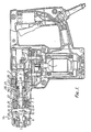
- the rotary percussive drill has a bit holder in the form of a tubular sleeve 1, one end of which has teeth 2 which engage a bevel gear 3 through which rotation about its longitudinal axis is imparted to the sleeve 1.
- the bevel gear 3 is driven by an electric motor 4 of infinitely variable speed.
- the motor 4 also provides a percussive drive through the medium of a pneumatically actuated ram 5 reciprocable in a hollow piston 6. As will be described more fully later the motor 4 reciprocates the piston 6 which, in the hammer mode, reciprocates the ram 5, the nose 18 of the ram striking a beat piece 7.
- the beat piece 7 is movable along the bore of the sleeve 1 and is located between the ram 5 and a bit (not shown).
- the bit is held in the sleeve 1 by releasable locking balls 8 and is rotatable by the sleeve 1 via driving elements one of which is indicated at 9.
- the beat piece 7 has two diametrically opposed axial recesses 10 located between the nose 11 of the beat piece and an end portion 11 a which is of reduced diameter as compared with the remainder of the beat piece and which is located in a smaller diameter bore 12 of the sleeve 1.
- the recesses 10 accommodate locking elements in the form of balls 13 that locate permanently in the recesses and engage the surface of an annular holder 14 maintained in contact with the face 15 of a mode change control member 16 of generally tubular form by a helical spring 17.
- the beat piece 7 is, in use, cyclically impacted by the nose 18 of the ram 5 as the latter is reciprocated in the hollow piston 6 and those impacts are transferred by the beat piece 7 to the bit.
- the sleeve is rotated about its longitudinal axis by the drive transmitted to gear 3 and this rotation is transferred to the bit by the driving elements 9.
- the hollow piston 6 is driven by a crank 20 rotated via gearing by the motor 4.
- the piston 6 has a stepped bore, the inner portion 21 of the bore being narrower than the outer portion 22 and the rear end of the ram 5 has a seal 23 which seals against the inner portion 21 of the bore but not against the outer portion 22.
- a closed chamber is defined behind the ram 5. This closed chamber provides an air cushion by which the ram 5 is reciprocated when the piston 6 is reciprocated.
- the mode change control member 15 is rotated so moving the balls 13 to the left as seen in the drawing and along the slots 1A and the recess 10.
- the balls 13 contact the lefthand (as seen in the drawing) end of the recess and continued rotation of the member 15 moves the beat piece 7 to the left (as seen in the drawing) by an amount sufficient to provide clearance between the end 11 and the nose 18 of the ram 5 when the latter is at the end of its impacting stroke.
- the beat piece 7 is not impacted by the nose of the ram and the bit is subject only to rotary movement.
- Figure 2A shows the ram in its most forward position when the tool is in the percussive mode. If the tool is now put in the non-percussive mode, the ram is able to advance through the position shown in Figure 2B to the position shown in Figure 2C in which the ram is at its most forward position. As the ram passes the position shown in Figure 2B, the nose of the ram enters the sleeve and a reduced diameter forward portion 24 of the ram enters an annular seal 25 of "U" shaped cross-section, with a shoulder 26 abutting the rear end of the seal 25.
- the seal 25 is fixed to a guide tube 29 in which the piston is mounted.
- the rear end of the ram enters the outer portion 22 of the bore.
- a port (not shown) is provided in the piston 6 at a location such that with the ram in the position shown in Figure 2C, the port is to the rear of the ram and the air cushion is vented.
- the member 15 is rotated in the reverse direction so allowing the balls 13 to return, under the action of spring 17, to the position shown in the drawing and, when the user presses the bit against a work piece, the beat piece is returned to its active position shown in Figure 1 and presses the ram 5 back into the position shown in Figure 1 whereupon the hammer action re-starts.
- the cam face may be so contoured that a 90° or 180° rotation of the member 15 is needed to complete the required axial movement of the balls 13 along the slots 1A.
- the contour of the cam face may, alternatively, be such that further rotation of the member 15 in the same direction allows the balls 13 to be returned to their original positions.
- control member 15 may be adapted to be moved axially and not rotated to effect the change between the hammer and non-hammer modes.
- the bit is subjected to percussive action of the beat piece only when the bit is pressed by the user against a work piece.
- Such pressure results in a small inward movement of the bit into the sleeve and of the beat piece towards the ram.
Claims (8)
Priority Applications (1)
| Application Number | Priority Date | Filing Date | Title |
|---|---|---|---|
| AT81305422T ATE11750T1 (de) | 1980-11-18 | 1981-11-17 | Schlagbohrgeraet. |
Applications Claiming Priority (2)
| Application Number | Priority Date | Filing Date | Title |
|---|---|---|---|
| GB8036916 | 1980-11-18 | ||
| GB8036916 | 1980-11-18 |
Publications (2)
| Publication Number | Publication Date |
|---|---|
| EP0052507A1 EP0052507A1 (fr) | 1982-05-26 |
| EP0052507B1 true EP0052507B1 (fr) | 1985-02-13 |
Family
ID=10517377
Family Applications (1)
| Application Number | Title | Priority Date | Filing Date |
|---|---|---|---|
| EP81305422A Expired EP0052507B1 (fr) | 1980-11-18 | 1981-11-17 | Perceuse à percussion |
Country Status (4)
| Country | Link |
|---|---|
| US (1) | US4442906A (fr) |
| EP (1) | EP0052507B1 (fr) |
| AT (1) | ATE11750T1 (fr) |
| DE (1) | DE3168959D1 (fr) |
Families Citing this family (52)
| Publication number | Priority date | Publication date | Assignee | Title |
|---|---|---|---|---|
| DE3429140A1 (de) * | 1984-08-08 | 1986-02-20 | Black & Decker Inc., Newark, Del. | Bohrhammer mit einem pneumatischen schlagwerk |
| DE3439475C2 (de) * | 1984-10-27 | 1996-02-01 | Bosch Gmbh Robert | Winkelvorsatz für schlagend und rotierend arbeitende Werkzeugmaschinen |
| DE3633675A1 (de) * | 1986-10-03 | 1988-04-14 | Hilti Ag | Bohrhammer mit schlagwerk |
| AT387505B (de) * | 1987-07-09 | 1989-02-10 | Woeber Irmfried | Haltevorrichtung fuer schriftgut, papierwaren od.dgl. |
| DE4239294A1 (de) * | 1992-11-23 | 1994-05-26 | Black & Decker Inc | Bohrhammer mit pneumatischem Schlagwerk |
| JP3424870B2 (ja) * | 1995-02-28 | 2003-07-07 | 株式会社マキタ | 打撃工具の空打ち防止装置 |
| JP3459493B2 (ja) * | 1995-05-25 | 2003-10-20 | 株式会社マキタ | 打撃工具 |
| DE19714287A1 (de) * | 1997-04-07 | 1998-10-08 | Hilti Ag | Bohr- und/oder Meisselgerät |
| DE19714288A1 (de) * | 1997-04-07 | 1998-10-08 | Hilti Ag | Bohr- und/oder Meisselgerät |
| DE19728729C2 (de) * | 1997-07-04 | 2000-11-09 | Wacker Werke Kg | Luftfeder-Schlagwerk mit Luftausgleich |
| DE19828426C2 (de) * | 1998-06-25 | 2003-04-03 | Wacker Werke Kg | Antriebskolben mit geringer Wandstärke für ein Luftfederschlagwerk |
| AU751720B2 (en) | 1998-09-18 | 2002-08-22 | Stanley Fastening Systems, L.P. | Multi-stroke fastening device |
| JP3794178B2 (ja) * | 1998-10-23 | 2006-07-05 | 日立工機株式会社 | 打撃工具 |
| GB9902789D0 (en) * | 1999-02-09 | 1999-03-31 | Black & Decker Inc | Rotary hammer |
| GB9902793D0 (en) | 1999-02-09 | 1999-03-31 | Black & Decker Inc | Rotary hammer |
| GB9909987D0 (en) * | 1999-04-30 | 1999-06-30 | Black & Decker Inc | Rotary hammer |
| DE19929183B4 (de) * | 1999-06-25 | 2004-07-29 | Wacker Construction Equipment Ag | Luftfederschlagwerk mit Hohl-Schlagkolben mit Leerlauföffnung |
| DE10019071A1 (de) * | 2000-04-18 | 2001-10-25 | Hilti Ag | Elekrohandwerkzeuggerät mit Leerschlagabschaltung |
| CA2311509C (fr) | 2000-06-14 | 2008-11-25 | Technologies Of Sterilization With Ozone Ts03 Inc. | Methode de controle de l'etat de sterilisation et indicateur connexe |
| DE10111748A1 (de) * | 2001-03-12 | 2002-09-19 | Hilti Ag | Schaltwerk für ein kombiniertes Handwerkzeuggerät |
| DE10294312T5 (de) * | 2001-09-17 | 2004-09-02 | Milwaukee Electric Tool Corp., Brookfield | Rotationshammer |
| JP3680941B2 (ja) * | 2002-01-18 | 2005-08-10 | マックス株式会社 | コンクリートドリル |
| EP1932627A3 (fr) * | 2003-03-21 | 2014-08-13 | Black & Decker, Inc. | Appareil de réduction de vibration pour outil électrique et outil électrique incorporant un tel appareil |
| ATE464983T1 (de) * | 2003-08-06 | 2010-05-15 | Hitachi Koki Kk | Schlagbohrer |
| JP4179159B2 (ja) * | 2003-12-18 | 2008-11-12 | 日立工機株式会社 | 打撃工具 |
| DE102004012433A1 (de) * | 2004-03-13 | 2005-09-29 | Robert Bosch Gmbh | Handwerkzeugmaschine |
| EP1674214B1 (fr) * | 2004-12-23 | 2008-05-28 | BLACK & DECKER INC. | Boitier pour outil à main motorisé |
| EP1674213B1 (fr) * | 2004-12-23 | 2008-10-01 | BLACK & DECKER INC. | Outil motorisé avec un dispositif de refroidissement |
| EP1674206A1 (fr) * | 2004-12-23 | 2006-06-28 | BLACK & DECKER INC. | Mécanisme de percussion d'un marteau à percussion à moteur |
| EP1674743B1 (fr) * | 2004-12-23 | 2014-01-22 | Black & Decker Inc. | Mécanisme d'entraînement pour outil motorisé |
| EP1674211A1 (fr) * | 2004-12-23 | 2006-06-28 | BLACK & DECKER INC. | Carter pour un outil motorisé |
| EP1872912B1 (fr) * | 2006-07-01 | 2014-03-19 | Black & Decker Inc. | Marteau perforateur avec une structure de support d'enclume |
| DE102006000395A1 (de) * | 2006-08-07 | 2008-02-14 | Hilti Ag | Handwerkzeugmaschine mit pneumatischem Schlagwerk |
| DE102006061627A1 (de) * | 2006-12-27 | 2008-07-10 | Robert Bosch Gmbh | Schlagwerk einer Elektrohandwerkzeugmaschine |
| GB0713432D0 (en) * | 2007-07-11 | 2007-08-22 | Black & Decker Inc | Rotary hammer-chain drive |
| DE102010029918A1 (de) * | 2010-06-10 | 2011-12-15 | Hilti Aktiengesellschaft | Werkzeugmaschine |
| DE102010029917A1 (de) * | 2010-06-10 | 2011-12-15 | Hilti Aktiengesellschaft | Werkzeugmaschine |
| TW201206656A (en) * | 2010-08-06 | 2012-02-16 | Top Gearbox Industry Co Ltd | Device incapable of generating vibration while reversely rotated |
| EP3517064B1 (fr) * | 2010-12-29 | 2023-09-06 | DePuy Synthes Products, Inc. | Outil entraîné par moteur électrique pour impact orthopédique |
| US8695726B2 (en) | 2010-12-29 | 2014-04-15 | Medical Enterprises LLC | Electric motor driven tool for orthopedic impacting |
| US8393409B2 (en) * | 2010-12-29 | 2013-03-12 | Ortho Technologies, Llc | Electric motor driven tool for orthopedic impacting |
| US8936105B2 (en) * | 2010-12-29 | 2015-01-20 | Medical Enterprises LLC | Electric motor driven tool for orthopedic impacting |
| DE102011014068A1 (de) * | 2011-03-16 | 2012-09-20 | Andreas Stihl Ag & Co. Kg | Handgeführtes Arbeitsgerät |
| JP5653843B2 (ja) * | 2011-06-02 | 2015-01-14 | 株式会社マキタ | 動力工具 |
| US10149711B2 (en) | 2012-03-30 | 2018-12-11 | Depuy Mitek, Llc | Surgical impact tool |
| US9630307B2 (en) * | 2012-08-22 | 2017-04-25 | Milwaukee Electric Tool Corporation | Rotary hammer |
| US9981372B2 (en) * | 2012-12-31 | 2018-05-29 | Robert Bosch Tool Corporation | Reciprocating tool with fluid driven counterweight |
| EP2921265A1 (fr) * | 2014-03-18 | 2015-09-23 | HILTI Aktiengesellschaft | Machine-outil portative |
| GB201812437D0 (en) * | 2018-07-31 | 2018-09-12 | Black & Decker Inc | Hammer drill |
| EP3822037A1 (fr) * | 2019-11-15 | 2021-05-19 | Hilti Aktiengesellschaft | Agencement de mécanisme de percussion |
| CN112296947A (zh) * | 2020-02-27 | 2021-02-02 | 杨新军 | 一种滑块撞击式冲击电钻 |
| US11642769B2 (en) * | 2021-02-22 | 2023-05-09 | Makita Corporation | Power tool having a hammer mechanism |
Citations (1)
| Publication number | Priority date | Publication date | Assignee | Title |
|---|---|---|---|---|
| EP0048482A1 (fr) * | 1980-09-22 | 1982-03-31 | Black & Decker Inc. | Perceuse rotative à percussion |
Family Cites Families (17)
| Publication number | Priority date | Publication date | Assignee | Title |
|---|---|---|---|---|
| GB547814A (en) * | 1941-07-14 | 1942-09-11 | Hardypick Ltd | Improvements in and relating to power hammers |
| GB810464A (en) * | 1954-11-12 | 1959-03-18 | Arno Jochums | Improvements in or relating to pneumatic tools |
| DE1283769B (de) * | 1963-05-15 | 1968-11-21 | Impex Essen Vertrieb | Schlaghammer |
| GB1195505A (en) * | 1967-07-31 | 1970-06-17 | Hilti Ag | Hammer Drill |
| CH532454A (fr) * | 1971-03-16 | 1973-01-15 | Etem Ets De Tech Mod | Outil pneumatique à percussion et rotation |
| US3921729A (en) * | 1971-11-25 | 1975-11-25 | Hilti Ag | Electropneumatic hammer |
| DE2229388C3 (de) * | 1972-06-16 | 1981-01-22 | Robert Bosch Gmbh, 7000 Stuttgart | Von Hand zu führender Bohrhammer |
| DE2242944B2 (de) * | 1972-08-31 | 1981-04-23 | Robert Bosch Gmbh, 7000 Stuttgart | Bohrhammer |
| DE2252951B2 (de) * | 1972-10-28 | 1981-09-10 | Robert Bosch Gmbh, 7000 Stuttgart | Bohrhammer |
| US3837409A (en) * | 1973-02-26 | 1974-09-24 | Skil Corp | Rotary hammer power tool |
| DE2516406C3 (de) * | 1975-04-15 | 1981-11-19 | Robert Bosch Gmbh, 7000 Stuttgart | Bohrhammer |
| FR2330507A1 (fr) * | 1975-11-04 | 1977-06-03 | Montabert Roger | Machine de percussion |
| DE2618596C2 (de) * | 1976-04-28 | 1984-05-17 | Robert Bosch Gmbh, 7000 Stuttgart | Werkzeughalter |
| DE2728961C2 (de) * | 1977-06-27 | 1991-08-08 | Hilti Ag, Schaan | Bohrhammer mit arretierbarem Werkzeughalter |
| DE2756993A1 (de) * | 1977-12-21 | 1979-07-05 | Duss Maschf | Elektropneumatischer hammer mit fangring fuer den schlagkolben |
| DE2820128A1 (de) * | 1978-05-09 | 1979-11-22 | Bosch Gmbh Robert | Handwerkzeugmaschine |
| US4290492A (en) * | 1979-01-31 | 1981-09-22 | Black & Decker Inc. | Idling and air replenishing system for a reciprocating hammer mechanism |
-
1981
- 1981-11-17 EP EP81305422A patent/EP0052507B1/fr not_active Expired
- 1981-11-17 AT AT81305422T patent/ATE11750T1/de not_active IP Right Cessation
- 1981-11-17 DE DE8181305422T patent/DE3168959D1/de not_active Expired
- 1981-11-17 US US06/322,389 patent/US4442906A/en not_active Expired - Lifetime
Patent Citations (1)
| Publication number | Priority date | Publication date | Assignee | Title |
|---|---|---|---|---|
| EP0048482A1 (fr) * | 1980-09-22 | 1982-03-31 | Black & Decker Inc. | Perceuse rotative à percussion |
Also Published As
| Publication number | Publication date |
|---|---|
| ATE11750T1 (de) | 1985-02-15 |
| DE3168959D1 (en) | 1985-03-28 |
| US4442906A (en) | 1984-04-17 |
| EP0052507A1 (fr) | 1982-05-26 |
Similar Documents
| Publication | Publication Date | Title |
|---|---|---|
| EP0052507B1 (fr) | Perceuse à percussion | |
| US4236588A (en) | Hammer drill with a lockable tool holder | |
| JP4195228B2 (ja) | ハンマー | |
| JP3292972B2 (ja) | 打撃工具 | |
| US4567951A (en) | Hammer drill | |
| US8240394B2 (en) | Hammer with vibration reduction mechanism | |
| US4657088A (en) | Rotary hammer driving mechanism | |
| CA1128384A (fr) | Mecanisme de mise en panne et d'apport d'air pour mecanisme de marteau piqueur | |
| US7818880B2 (en) | Ram for powered hammer | |
| US3114423A (en) | Rotary-hammer device | |
| US4310055A (en) | Percussion hammer with a one piece striker | |
| GB2102718A (en) | Improvements in or relating to rotary percussive drills | |
| US4718500A (en) | Reversible percussion device for percussion tool | |
| US4669553A (en) | Percussion tool | |
| GB2084917A (en) | Improvements in or relating to percussive tools | |
| GB2085795A (en) | A hammer drill | |
| US3167135A (en) | Anvil impact tool | |
| EP0048482B1 (fr) | Perceuse rotative à percussion | |
| GB2114495A (en) | Impact tool | |
| EP0012438B1 (fr) | Outils à percussion | |
| GB2099748A (en) | A hammer drill | |
| RU2244621C1 (ru) | Ударная машина | |
| KR200153172Y1 (ko) | 전기햄머드릴 | |
| JPH0417343Y2 (fr) | ||
| JPH0417344Y2 (fr) |
Legal Events
| Date | Code | Title | Description |
|---|---|---|---|
| PUAI | Public reference made under article 153(3) epc to a published international application that has entered the european phase |
Free format text: ORIGINAL CODE: 0009012 |
|
| AK | Designated contracting states |
Designated state(s): AT BE CH DE FR GB IT LU NL SE |
|
| 17P | Request for examination filed |
Effective date: 19820917 |
|
| ITF | It: translation for a ep patent filed |
Owner name: BARZANO' E ZANARDO MILANO S.P.A. |
|
| GRAA | (expected) grant |
Free format text: ORIGINAL CODE: 0009210 |
|
| AK | Designated contracting states |
Designated state(s): AT BE CH DE FR GB IT LI LU NL SE |
|
| PG25 | Lapsed in a contracting state [announced via postgrant information from national office to epo] |
Ref country code: SE Effective date: 19850213 Ref country code: LI Effective date: 19850213 Ref country code: CH Effective date: 19850213 Ref country code: AT Effective date: 19850213 |
|
| REF | Corresponds to: |
Ref document number: 11750 Country of ref document: AT Date of ref document: 19850215 Kind code of ref document: T |
|
| REF | Corresponds to: |
Ref document number: 3168959 Country of ref document: DE Date of ref document: 19850328 |
|
| ET | Fr: translation filed | ||
| REG | Reference to a national code |
Ref country code: CH Ref legal event code: PL |
|
| PG25 | Lapsed in a contracting state [announced via postgrant information from national office to epo] |
Ref country code: LU Free format text: LAPSE BECAUSE OF NON-PAYMENT OF DUE FEES Effective date: 19851130 |
|
| PLBE | No opposition filed within time limit |
Free format text: ORIGINAL CODE: 0009261 |
|
| STAA | Information on the status of an ep patent application or granted ep patent |
Free format text: STATUS: NO OPPOSITION FILED WITHIN TIME LIMIT |
|
| 26N | No opposition filed | ||
| PGFP | Annual fee paid to national office [announced via postgrant information from national office to epo] |
Ref country code: LU Payment date: 19891031 Year of fee payment: 9 |
|
| PGFP | Annual fee paid to national office [announced via postgrant information from national office to epo] |
Ref country code: NL Payment date: 19891130 Year of fee payment: 9 |
|
| PGFP | Annual fee paid to national office [announced via postgrant information from national office to epo] |
Ref country code: BE Payment date: 19891212 Year of fee payment: 9 |
|
| PG25 | Lapsed in a contracting state [announced via postgrant information from national office to epo] |
Ref country code: BE Effective date: 19901130 |
|
| BERE | Be: lapsed |
Owner name: BLACK & DECKER INC. Effective date: 19901130 |
|
| PG25 | Lapsed in a contracting state [announced via postgrant information from national office to epo] |
Ref country code: NL Effective date: 19910601 |
|
| NLV4 | Nl: lapsed or anulled due to non-payment of the annual fee | ||
| ITTA | It: last paid annual fee | ||
| PGFP | Annual fee paid to national office [announced via postgrant information from national office to epo] |
Ref country code: FR Payment date: 20001101 Year of fee payment: 20 |
|
| PGFP | Annual fee paid to national office [announced via postgrant information from national office to epo] |
Ref country code: DE Payment date: 20001102 Year of fee payment: 20 |
|
| PGFP | Annual fee paid to national office [announced via postgrant information from national office to epo] |
Ref country code: GB Payment date: 20001103 Year of fee payment: 20 |
|
| PG25 | Lapsed in a contracting state [announced via postgrant information from national office to epo] |
Ref country code: GB Free format text: LAPSE BECAUSE OF EXPIRATION OF PROTECTION Effective date: 20011116 |
|
| REG | Reference to a national code |
Ref country code: GB Ref legal event code: PE20 Effective date: 20011116 |