EP1674206A1 - Mécanisme de percussion d'un marteau à percussion à moteur - Google Patents
Mécanisme de percussion d'un marteau à percussion à moteur Download PDFInfo
- Publication number
- EP1674206A1 EP1674206A1 EP05022982A EP05022982A EP1674206A1 EP 1674206 A1 EP1674206 A1 EP 1674206A1 EP 05022982 A EP05022982 A EP 05022982A EP 05022982 A EP05022982 A EP 05022982A EP 1674206 A1 EP1674206 A1 EP 1674206A1
- Authority
- EP
- European Patent Office
- Prior art keywords
- hollow piston
- tool
- guide rods
- crank
- housing
- Prior art date
- Legal status (The legal status is an assumption and is not a legal conclusion. Google has not performed a legal analysis and makes no representation as to the accuracy of the status listed.)
- Withdrawn
Links
Images


Classifications
-
- B—PERFORMING OPERATIONS; TRANSPORTING
- B25—HAND TOOLS; PORTABLE POWER-DRIVEN TOOLS; MANIPULATORS
- B25D—PERCUSSIVE TOOLS
- B25D11/00—Portable percussive tools with electromotor or other motor drive
- B25D11/06—Means for driving the impulse member
- B25D11/12—Means for driving the impulse member comprising a crank mechanism
- B25D11/125—Means for driving the impulse member comprising a crank mechanism with a fluid cushion between the crank drive and the striking body
-
- B—PERFORMING OPERATIONS; TRANSPORTING
- B25—HAND TOOLS; PORTABLE POWER-DRIVEN TOOLS; MANIPULATORS
- B25D—PERCUSSIVE TOOLS
- B25D16/00—Portable percussive machines with superimposed rotation, the rotational movement of the output shaft of a motor being modified to generate axial impacts on the tool bit
-
- B—PERFORMING OPERATIONS; TRANSPORTING
- B25—HAND TOOLS; PORTABLE POWER-DRIVEN TOOLS; MANIPULATORS
- B25D—PERCUSSIVE TOOLS
- B25D17/00—Details of, or accessories for, portable power-driven percussive tools
- B25D17/06—Hammer pistons; Anvils ; Guide-sleeves for pistons
-
- B—PERFORMING OPERATIONS; TRANSPORTING
- B25—HAND TOOLS; PORTABLE POWER-DRIVEN TOOLS; MANIPULATORS
- B25D—PERCUSSIVE TOOLS
- B25D2211/00—Details of portable percussive tools with electromotor or other motor drive
- B25D2211/003—Crossed drill and motor spindles
-
- B—PERFORMING OPERATIONS; TRANSPORTING
- B25—HAND TOOLS; PORTABLE POWER-DRIVEN TOOLS; MANIPULATORS
- B25D—PERCUSSIVE TOOLS
- B25D2217/00—Details of, or accessories for, portable power-driven percussive tools
- B25D2217/0011—Details of anvils, guide-sleeves or pistons
- B25D2217/0019—Guide-sleeves
-
- B—PERFORMING OPERATIONS; TRANSPORTING
- B25—HAND TOOLS; PORTABLE POWER-DRIVEN TOOLS; MANIPULATORS
- B25D—PERCUSSIVE TOOLS
- B25D2250/00—General details of portable percussive tools; Components used in portable percussive tools
- B25D2250/231—Sleeve details
- B25D2250/235—Sleeve couplings
-
- B—PERFORMING OPERATIONS; TRANSPORTING
- B25—HAND TOOLS; PORTABLE POWER-DRIVEN TOOLS; MANIPULATORS
- B25D—PERCUSSIVE TOOLS
- B25D2250/00—General details of portable percussive tools; Components used in portable percussive tools
- B25D2250/331—Use of bearings
Definitions
- the present invention relates to a hammer mechanism for a power tool, and to a power tool incorporating such a mechanism.
- the invention relates particularly, but not exclusively to a hammer mechanism for a hammer drill having a hammer mode, a rotary mode, and a combined hammer and rotary mode, and to a power tool incorporating such a mechanism.
- Hammer drills are power tools, which can generally operate in one of three modes of operation.
- a hammer drill will have a tool bit, which can be operated in a hammering mode, a drilling mode and a combined hammering and drilling mode.
- European patent application EP0775556 describes a drive mechanism for such a hammer drill.
- This mechanism comprises a hollow piston in which a ram member is slidably disposed.
- the hollow piston is slidably mounted on a pair of guide rods and connected at the rear of the hollow piston to a wobble plate such that the hollow piston can be reciprocated back and forth along the guide rods by means of the wobble plate when a motor of the drill is actuated.
- the reciprocation of the hollow piston causes the ram member to move with the piston and cause compression of the air in the piston, which in turn causes the ram to impart impacts on an end of the tool bit, thus causing the hammering action of the power tool.
- the tool bit is also mounted in a spindle which is caused to rotate by the electric motor of the tool for the drilling mode.
- EP0775556 suffers from the drawback that as the reciprocation of the hollow piston is driven by a wobble plate mounted at the rear of the hollow piston, the mechanism for causing this reciprocation is relatively large in the direction of reciprocating motion, and it is difficult to make the mechanism of compact construction in that direction.
- DE19856638 discloses a hammer drill in which a piston is reciprocally driven by means of a wobble plate connected to a side of the piston, in order to impart impacts to a drill bit.
- this arrangement can be made more compactly than the arrangement of EP0775556 in the direction of reciprocating motion of the piston, the provision of a wobble plate on one side of the piston prevents the drill from being made compact in a direction transverse to the direction of reciprocating motion.
- Preferred embodiments of the present invention seek to overcome the above disadvantages of the prior art.
- a hammer mechanism for a power tool having a housing and a motor disposed in the housing and having an output shaft for actuating a tool bit of the tool, the hammer mechanism comprising:-
- the guide rods provide the advantage of enabling the mechanism to be of lightweight and strong construction, while the engagement of the drive member with the side of the hollow member enables the mechanism to be of compact construction in the direction of reciprocating movement.
- At least one said hollow piston is slidably mounted on two guide rods having longitudinal axes substantially parallel to each other.
- At least one said drive member may engage at least one said hollow piston at a point between the respective guide rods.
- At least one said drive member engages at least one hollow piston on an underside of the hollow piston.
- this provides the advantage of reducing the length and width of the hammer mechanism. It is ergonomically preferable to decrease the length and width of the tool rather than the height of the tool, to enable easier handling of the tool.
- the mechanism may further comprise at least one crank member adapted to engage a side of said hollow piston and to rotate about an axis to cause reciprocating movement of said hollow piston.
- This provides the advantage of enabling the mechanism to be of more compact construction than a mechanism incorporating one or more wobble plates.
- the mechanism may further comprise at least one crank plate adapted to be rotated by means of said output shaft, and a respective crank pin eccentrically mounted on at least one said crank plate and pivotally connected to a respective said crank member such that rotation of the crank plate causes reciprocation of a said hollow piston along a plurality of said guide rods.
- the mechanism may further comprise rotation means for rotating a tool bit of the tool by means of said motor.
- the rotation means may comprise a drive shaft extending transversely to an axis of rotation of the tool bit.
- a power tool comprising a housing, a motor disposed in the housing and having an output shaft for actuating a tool bit of the tool, and a hammer mechanism as defined above.
- the power tool is a hammer drill.
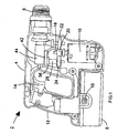
- a hammer drill shown generally by 2 comprises a housing 4 formed from two clam shell halves of durable plastics material, as will be understood by persons skilled in the art. Extending from a forward end of housing 4 is a chuck 6 or similar device for gripping a tool bit. A rechargeable battery pack 8 is removably attached to the bottom of the housing, and can be removed from the housing 4 by depressing clips 10 to release the battery pack for recharging.
- the housing 4 comprises a handle portion 12 having a trigger 14 for activation of the hammer drill by means of an electric motor 16 disposed in the housing.
- An output shaft 18 extends from the electric motor 16, the output shaft 18 having a pinion 20 formed thereon.
- the pinion 20 has a plurality of gear teeth formed on its outer surface (not shown).
- pinion 20 of output shaft 18 intermeshes with a first gear 22 and a second gear 24.
- gears 22 and 24 will also rotate.
- a first drive shaft 26 is fixed to gear 22 such that first drive shaft 26 rotates with first gear 22
- second drive shaft 28 is fixed to second gear 24 such that second drive shaft 28 rotates with second gear 24.
- first bevel gear 32 is mounted at the upper end of first drive shaft 26 such that first bevel gear 32 rotates with drive shaft 26.
- a second bevel gear 34 is mounted to a spindle 36 for receiving a drill bit (not shown), the spindle 36 being rotatably mounted in the housing about axis 37.
- the bevel gears 32, 34 mesh with each other such that rotation of first bevel gear 32 causes second bevel gear 34 to rotate about axis 37. This provides the drilling action.
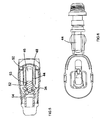
- crank pin 40 drives crank arm 42, and due to the pivotal connection between crank arm 42 and the underside of hollow piston 44, the hollow piston is caused to reciprocate back and forth along guide rods 48, 50.
- a ram member 52 is slidably disposed in the bore 46 of hollow piston 44, and an o-ring 53 ( Figure 5) is arranged between the ram member 52 and the internal surface of the piston 44.
- the ram member 52 forms a seal with the interior of the hollow piston 44 such that on reciprocation of hollow piston 44 the ram member 52 oscillates relative to the piston 44 under an air spring affect.
- the ram member comprises a forward end 54 which passes into spindle 36. As the ram member 52 oscillates, the forward end 54 of ram member 52 strikes the rear portion of a tool bit (not shown) to provide a hammer action of the drill.
- a mode change mechanism allows the user to select one of the hammer mode, the rotary mode, or the combined hammer and rotary mode.
- the hammer mode is selected by disengagement of the gear 22 from the pinion 20.
- the rotary mode is selected by disengagement of the gear 24 from the pinion 20.
- the combined hammer and rotary mode is selected when both of the gears 22 or 24 remain engaged with the pinion 20.
- hollow piston 44 slidably mounted to guide rods 48, 50, together with crank pin 40 engaging the underside of the hollow piston 44 enables the drill to be of considerably more compact construction than the prior art.
Landscapes
- Engineering & Computer Science (AREA)
- Mechanical Engineering (AREA)
- Percussive Tools And Related Accessories (AREA)
Applications Claiming Priority (2)
| Application Number | Priority Date | Filing Date | Title |
|---|---|---|---|
| GB0428215A GB0428215D0 (en) | 2004-12-23 | 2004-12-23 | Piston Drive Mechanism |
| GB0516506A GB2421465A (en) | 2004-12-23 | 2005-08-11 | Hammer mechanism for a power tool |
Publications (1)
| Publication Number | Publication Date |
|---|---|
| EP1674206A1 true EP1674206A1 (fr) | 2006-06-28 |
Family
ID=36046957
Family Applications (1)
| Application Number | Title | Priority Date | Filing Date |
|---|---|---|---|
| EP05022982A Withdrawn EP1674206A1 (fr) | 2004-12-23 | 2005-10-21 | Mécanisme de percussion d'un marteau à percussion à moteur |
Country Status (4)
| Country | Link |
|---|---|
| US (1) | US20060137889A1 (fr) |
| EP (1) | EP1674206A1 (fr) |
| JP (1) | JP2006175584A (fr) |
| AU (1) | AU2005229727A1 (fr) |
Cited By (3)
| Publication number | Priority date | Publication date | Assignee | Title |
|---|---|---|---|---|
| EP1949992A1 (fr) * | 2007-01-25 | 2008-07-30 | Metabowerke GmbH | Marteau perforateur électrique ou perceuse électrique à percussion |
| EP2937185A1 (fr) * | 2014-04-22 | 2015-10-28 | HILTI Aktiengesellschaft | Machine-outil portative |
| WO2017108420A1 (fr) * | 2015-12-22 | 2017-06-29 | Robert Bosch Gmbh | Machine-outil portative et procédé de fabrication d'une machine-outil portative |
Families Citing this family (8)
| Publication number | Priority date | Publication date | Assignee | Title |
|---|---|---|---|---|
| US9016395B2 (en) * | 2010-11-16 | 2015-04-28 | Milwaukee Electric Tool Corporation | Impact tool |
| US20150174744A1 (en) * | 2010-11-16 | 2015-06-25 | Techtronic Industries Co. Ltd. | Impact tool |
| US9630307B2 (en) | 2012-08-22 | 2017-04-25 | Milwaukee Electric Tool Corporation | Rotary hammer |
| DE102013210391A1 (de) * | 2013-06-05 | 2014-12-11 | Robert Bosch Gmbh | Elektrowerkzeug |
| GB201421576D0 (en) | 2014-12-04 | 2015-01-21 | Black & Decker Inc | Drill |
| GB201421577D0 (en) * | 2014-12-04 | 2015-01-21 | Black & Decker Inc | Drill |
| USD921072S1 (en) * | 2017-11-22 | 2021-06-01 | Kjell Andersson | Core drill attachment |
| EP3782766A1 (fr) * | 2019-08-19 | 2021-02-24 | Hilti Aktiengesellschaft | Machine-outil manuelle |
Citations (6)
| Publication number | Priority date | Publication date | Assignee | Title |
|---|---|---|---|---|
| GB969007A (en) * | 1960-03-30 | 1964-09-09 | Skil Corp | Rotary hammer device |
| US3191694A (en) * | 1962-03-05 | 1965-06-29 | John Lynn & Co Ltd | Percussive tools |
| GB2038986A (en) * | 1978-12-13 | 1980-07-30 | Black & Decker Inc | Converting rotary motion to reciprocatory motion |
| US4370916A (en) * | 1979-10-04 | 1983-02-01 | Mitin Leonid A | Percussive device |
| EP0560512A1 (fr) * | 1992-03-07 | 1993-09-15 | Black & Decker Inc. | Perceuse à percussion |
| EP0775556A1 (fr) * | 1995-11-27 | 1997-05-28 | Black & Decker Inc. | Mécanisme de marteau |
Family Cites Families (30)
| Publication number | Priority date | Publication date | Assignee | Title |
|---|---|---|---|---|
| US1740701A (en) * | 1921-10-17 | 1929-12-24 | Sullivan Machinery Co | Drilling mechanism |
| GB1030136A (en) * | 1963-10-23 | 1966-05-18 | Kango Electric Hammers Ltd | Improvements relating to power-operated percussive tools |
| US3583619A (en) * | 1968-10-31 | 1971-06-08 | Donald O Shepherd | Yarn accumulator |
| DE1938660C3 (de) * | 1969-07-30 | 1975-05-15 | Metabowerke Kg, Closs, Rauch & Schnizler, 7440 Nuertingen | Schlagbohrhammer |
| DE1964083C3 (de) * | 1969-12-22 | 1983-01-27 | Robert Bosch Gmbh, 7000 Stuttgart | Gesteinsbohrmaschine |
| US3921729A (en) * | 1971-11-25 | 1975-11-25 | Hilti Ag | Electropneumatic hammer |
| US3834469A (en) * | 1972-11-14 | 1974-09-10 | Wacker Werke Kg | Internal combustion operated hammer |
| US4014392A (en) * | 1973-03-01 | 1977-03-29 | Ross Frederick W | Stabilized piston-cylinder impact device |
| DE2449191C2 (de) * | 1974-10-16 | 1988-03-24 | Robert Bosch Gmbh, 7000 Stuttgart | Hammer |
| NL7504371A (nl) * | 1975-04-11 | 1976-10-13 | Kooten Bv V | Heihamer. |
| US4340120A (en) * | 1978-03-20 | 1982-07-20 | Hawk Industries, Inc. | Annular casing hammer |
| US4436163A (en) * | 1978-12-13 | 1984-03-13 | Black & Decker Inc. | Arrangement for converting rotary motion to reciprocatory motion |
| US4285550A (en) * | 1979-10-15 | 1981-08-25 | Blackburn Robert V | Weight transfer roller apparatus |
| US4382637A (en) * | 1979-10-15 | 1983-05-10 | Blackburn Robert V | Weight transfer roller apparatus |
| SE433907B (sv) * | 1980-05-30 | 1984-06-25 | Duni Bila Ab | Formanpassande dyna |
| US4442906A (en) * | 1980-11-18 | 1984-04-17 | Black & Decker Inc. | Percussive drills |
| DE3304916A1 (de) * | 1983-02-12 | 1984-08-16 | Robert Bosch Gmbh, 7000 Stuttgart | Bohrhammer |
| DE3590888T1 (fr) * | 1985-12-23 | 1988-03-10 | ||
| JPS62264879A (ja) * | 1986-05-14 | 1987-11-17 | 芝浦メカトロニクス株式会社 | 衝撃工具 |
| US4823127A (en) * | 1987-04-20 | 1989-04-18 | Hazeltine Corporation | Automatic, real-time fault monitor verifying network in a microwave landing system |
| GB9124016D0 (en) * | 1991-11-12 | 1992-01-02 | Johnson Electric Sa | An angularly biassed self-aligning bearing |
| US5320177A (en) * | 1992-03-30 | 1994-06-14 | Makita Corporation | Power driven hammer drill |
| DE4239294A1 (de) * | 1992-11-23 | 1994-05-26 | Black & Decker Inc | Bohrhammer mit pneumatischem Schlagwerk |
| JP3062436B2 (ja) * | 1996-07-09 | 2000-07-10 | 株式会社ユニクラ | 斜板式圧縮機 |
| DE19717712A1 (de) * | 1997-04-18 | 1998-10-22 | Black & Decker Inc | Bohrhammer |
| US6257767B1 (en) * | 1999-08-27 | 2001-07-10 | Emerson Electric Co. | Reduced cost bearing retainer |
| US6648511B2 (en) * | 2000-07-10 | 2003-11-18 | Fasco Industries, Inc. | Electric motor bearing system and journal |
| GB0109747D0 (en) * | 2001-04-20 | 2001-06-13 | Black & Decker Inc | Hammer |
| DE10121088A1 (de) * | 2001-04-28 | 2002-11-07 | Bosch Gmbh Robert | Bohr- und/oder Meißelhammer |
| GB0213464D0 (en) * | 2002-06-12 | 2002-07-24 | Black & Decker Inc | Hammer |
-
2005
- 2005-10-21 EP EP05022982A patent/EP1674206A1/fr not_active Withdrawn
- 2005-11-04 AU AU2005229727A patent/AU2005229727A1/en not_active Abandoned
- 2005-11-11 JP JP2005327276A patent/JP2006175584A/ja active Pending
- 2005-12-21 US US11/314,523 patent/US20060137889A1/en not_active Abandoned
Patent Citations (6)
| Publication number | Priority date | Publication date | Assignee | Title |
|---|---|---|---|---|
| GB969007A (en) * | 1960-03-30 | 1964-09-09 | Skil Corp | Rotary hammer device |
| US3191694A (en) * | 1962-03-05 | 1965-06-29 | John Lynn & Co Ltd | Percussive tools |
| GB2038986A (en) * | 1978-12-13 | 1980-07-30 | Black & Decker Inc | Converting rotary motion to reciprocatory motion |
| US4370916A (en) * | 1979-10-04 | 1983-02-01 | Mitin Leonid A | Percussive device |
| EP0560512A1 (fr) * | 1992-03-07 | 1993-09-15 | Black & Decker Inc. | Perceuse à percussion |
| EP0775556A1 (fr) * | 1995-11-27 | 1997-05-28 | Black & Decker Inc. | Mécanisme de marteau |
Cited By (3)
| Publication number | Priority date | Publication date | Assignee | Title |
|---|---|---|---|---|
| EP1949992A1 (fr) * | 2007-01-25 | 2008-07-30 | Metabowerke GmbH | Marteau perforateur électrique ou perceuse électrique à percussion |
| EP2937185A1 (fr) * | 2014-04-22 | 2015-10-28 | HILTI Aktiengesellschaft | Machine-outil portative |
| WO2017108420A1 (fr) * | 2015-12-22 | 2017-06-29 | Robert Bosch Gmbh | Machine-outil portative et procédé de fabrication d'une machine-outil portative |
Also Published As
| Publication number | Publication date |
|---|---|
| JP2006175584A (ja) | 2006-07-06 |
| AU2005229727A1 (en) | 2006-07-13 |
| US20060137889A1 (en) | 2006-06-29 |
Similar Documents
| Publication | Publication Date | Title |
|---|---|---|
| EP1674206A1 (fr) | Mécanisme de percussion d'un marteau à percussion à moteur | |
| EP2138278B1 (fr) | Poignée pour un outil électrique | |
| JP4874978B2 (ja) | ハンマドリル用のロック式トリガボタン | |
| EP1690642B1 (fr) | Machine portative à percussion | |
| JP4828926B2 (ja) | ハンマードリル | |
| RU2551736C2 (ru) | Приводной инструмент с питанием от аккумуляторной батареи | |
| CN100515687C (zh) | 动力工具 | |
| EP1477280A3 (fr) | Perceuse à percussion | |
| EP1690646A1 (fr) | Machine portative à percussion | |
| EP1690640A1 (fr) | Machine portative à percussion | |
| RU2455144C2 (ru) | Электрическая ручная машина для сверления в ударно-вращательном режиме или долбления | |
| JP2010005751A (ja) | 手持式作業工具 | |
| US7398835B2 (en) | Rotary hammer having both a reciprocating hammer mechanism and a ratcheting hammer mechanism | |
| US11571796B2 (en) | Rotary hammer | |
| US20100270045A1 (en) | Handheld power tool | |
| GB2421465A (en) | Hammer mechanism for a power tool | |
| EP4319944A1 (fr) | Outil électrique à percussion | |
| EP2883659A1 (fr) | Mécanisme d'entraînement de marteau | |
| EP3568265B1 (fr) | Outil oscillant à multiples angles d'oscillation | |
| WO2012144568A1 (fr) | Outil à percussion | |
| KR101059687B1 (ko) | 해머와 드릴 기능을 가지는 전동공구 | |
| EP4257293A1 (fr) | Perforateur rotatif | |
| CN113183098B (zh) | 冲击钻 | |
| JP7412135B2 (ja) | 打撃工具 | |
| CN215545159U (zh) | 锂电冲击钻 |
Legal Events
| Date | Code | Title | Description |
|---|---|---|---|
| PUAI | Public reference made under article 153(3) epc to a published international application that has entered the european phase |
Free format text: ORIGINAL CODE: 0009012 |
|
| AK | Designated contracting states |
Kind code of ref document: A1 Designated state(s): AT BE BG CH CY CZ DE DK EE ES FI FR GB GR HU IE IS IT LI LT LU LV MC NL PL PT RO SE SI SK TR |
|
| AX | Request for extension of the european patent |
Extension state: AL BA HR MK YU |
|
| 17P | Request for examination filed |
Effective date: 20060707 |
|
| 17Q | First examination report despatched |
Effective date: 20060823 |
|
| AKX | Designation fees paid |
Designated state(s): AT BE BG CH CY CZ DE DK EE ES FI FR GB GR HU IE IS IT LI LT LU LV MC NL PL PT RO SE SI SK TR |
|
| STAA | Information on the status of an ep patent application or granted ep patent |
Free format text: STATUS: THE APPLICATION IS DEEMED TO BE WITHDRAWN |
|
| 18D | Application deemed to be withdrawn |
Effective date: 20090915 |