EP0052223B1 - Kühlvorrichtung für ein Formwerkzeug - Google Patents
Kühlvorrichtung für ein Formwerkzeug Download PDFInfo
- Publication number
- EP0052223B1 EP0052223B1 EP81108062A EP81108062A EP0052223B1 EP 0052223 B1 EP0052223 B1 EP 0052223B1 EP 81108062 A EP81108062 A EP 81108062A EP 81108062 A EP81108062 A EP 81108062A EP 0052223 B1 EP0052223 B1 EP 0052223B1
- Authority
- EP
- European Patent Office
- Prior art keywords
- pivot
- pivot spindle
- conduit
- fluid
- cooling arrangement
- Prior art date
- Legal status (The legal status is an assumption and is not a legal conclusion. Google has not performed a legal analysis and makes no representation as to the accuracy of the status listed.)
- Expired
Links
Images


Classifications
-
- C—CHEMISTRY; METALLURGY
- C03—GLASS; MINERAL OR SLAG WOOL
- C03B—MANUFACTURE, SHAPING, OR SUPPLEMENTARY PROCESSES
- C03B9/00—Blowing glass; Production of hollow glass articles
- C03B9/30—Details of blowing glass; Use of materials for the moulds
- C03B9/38—Means for cooling, heating, or insulating glass-blowing machines or for cooling the glass moulded by the machine
- C03B9/3875—Details thereof relating to the side-wall, body or main part of the moulds
-
- C—CHEMISTRY; METALLURGY
- C03—GLASS; MINERAL OR SLAG WOOL
- C03B—MANUFACTURE, SHAPING, OR SUPPLEMENTARY PROCESSES
- C03B9/00—Blowing glass; Production of hollow glass articles
- C03B9/30—Details of blowing glass; Use of materials for the moulds
- C03B9/34—Glass-blowing moulds not otherwise provided for
- C03B9/353—Mould holders ; Mould opening and closing mechanisms
- C03B9/3532—Mechanisms for holders of half moulds moving by rotation about a common vertical axis
-
- C—CHEMISTRY; METALLURGY
- C03—GLASS; MINERAL OR SLAG WOOL
- C03B—MANUFACTURE, SHAPING, OR SUPPLEMENTARY PROCESSES
- C03B9/00—Blowing glass; Production of hollow glass articles
- C03B9/30—Details of blowing glass; Use of materials for the moulds
- C03B9/38—Means for cooling, heating, or insulating glass-blowing machines or for cooling the glass moulded by the machine
- C03B9/3808—Selection or characteristics of the cooling, heating or insulating medium, e.g. gas composition, moisture content, cryogenic state
Definitions
- the invention relates to a cooling device for a mold, which can be cooled by a pressure fluid, in particular air, of a machine for processing thermoplastic materials, in particular molten glass, with at least one spatially fixed feed channel for the fluid and with each feed channel with a fluid distribution device for that relative to the
- the feed channel which is pivotable about a first pivot axis, connects the connecting tool, which is pivotable relative to the feed channel and relative to the fluid distribution device.
- the connecting channel is designed as a telescopic tube, the two free ends of which are each connected to a part of a hollow sphere that is open on both sides.
- the hollow ball parts are each pivotally mounted in a ball socket of the feed channel and the fluid distribution device.
- the disadvantage here is the comparatively small permissible pivoting angle of the fluid distribution device and thus of the mold, which is caused by the ball joints. As a result, a certain axial minimum length of the molds cannot be exceeded. Furthermore, in the case of molds of relatively short axial length, the fluid can finally be fed into the fluid distribution device only in the axial end region of the mold at the greatest possible distance from the feed channel.
- the object of the invention is to increase the swivel angle permissible for the molding tool independently of the axial length of the molding tool and to enable fluid feed into the fluid distribution device in any axial plane of the molding tool.
- the joint channel parts can be given any desired extension in the pivoting direction in a simple manner. Depending on the available space in the machine, the swiveling paths of the articulated duct parts can also be placed cheaply.
- the molding tool can be both a single shape and a multiple shape.
- the feed duct can be installed in a machine-fixed manner or can be part of a fan line installed in the factory hall.
- the first pivot axis, about which the parts of the molding tool pivot, is preferably a hinge column on which pliers arms carrying the molding tool parts are pivotably mounted.
- the gap seals according to claim 3 are simple and reliable and lead to only insignificant fluid leakage losses, especially given the relatively low blower pressure of the fluid.
- the extension pieces according to claim 4 allow an adaptation of the cooling device to different molds with the least possible effort.
- the joint channel parts can remain unchanged when changing the type of mold.
- the features of claim 11 then permit a light and space-saving design of the first articulated duct part if the second pivot axis is arranged parallel to, ie at a distance from, the longitudinal axis of the feed duct.
- the first articulated channel part can advantageously be formed according to claim 12.
- a light, simple and space-saving design of the second joint duct part is obtained according to the provision of claim 13.
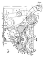
- FIG. 1 shows a preform side 1 of a station 2 of a so-called I.S. glass molding machine.
- station 2 drops of molten or viscous glass coming from a drop feeder (not shown) are formed into hollow glass objects in the press-blow process.
- a vertically standing hinge column 4 is fixedly connected to a machine frame 3 of station 2, on which preform pliers halves 5 and 6 are pivotably mounted.
- Fig.1 the preforming pliers half is drawn in its closed position and the preforming pliers half 6 in their most open position by an angle 7.
- a rear arm 8 is fastened to the preforming pliers half and is articulated to a tab 10 via a bolt 9.
- a rear arm 11 extends from the preforming pliers half 6 and is coupled via a bolt 12 to a tab 13 which is articulated on a crank pin 14 of a crank 16 fastened to a drive shaft 15.
- the tab 10 can be driven in a similar manner.
- a rocker 19 is pivotally mounted on a rocker pin 18, into which two preform halves (not shown in FIG. 1) (see FIG. 20 in FIG. 2) of a mold 21 designed as a double mold can be hung.
- the molding tool 21 also has two split mouth tools 22 and 23, which are mounted on the station 2 in a manner known per se, independently of the preform pliers halves 5, 6.
- the muzzle tool 22 has muzzle tool halves 24 and 25 and the muzzle tool 23 has muzzle tool halves 26 and 27.
- the preforming pliers half is designed and equipped in the same way as the preforming pliers half 5 and bears not shown, complementary to the preforming halves 20 preforming halves.
- the preforming pliers halves 5,6 overlap lower areas of the preform halves, e.g. B. 20, upper regions of the closed mouth tools 22, 23rd
- Press rams 28 and 29 penetrate centrally from below through the mouth tools 22, 23 into the interior of the closed preform halves, e.g. B. 20, and each form a parison from the previously introduced into the preforms 30 and 31 glass batch.
- the hinge pillar 4 forms a first pivot axis with a longitudinal axis 32.
- a first joint channel part 35 can be pivoted about a second pivot axis 33 with a longitudinal axis 34 that is parallel to the first pivot axis 4 and is fixed relative to the machine frame 3.
- the first articulated channel part 35 has an inlet opening 37 for a fluid, for example, an outlet opening 37 which extends on a circular ring piece about the second pivot axis 33 and is permanently connected to a machine-fixed supply channel 36. B. blown air to cool the mold 21.
- the feed channel 36 has a longitudinal axis 38 which runs parallel to the longitudinal axis 34.
- a third pivot axis 39 with a longitudinal axis 40 parallel to the longitudinal axis 34 is fastened to the first articulated channel part 35 in the manner shown in detail in FIG.
- a second joint channel part 41 can be pivoted about the third pivot axis 39.
- the second articulated channel part 41 takes over the fluid from the first articulated channel part 35 and forwards it into a fluid distribution box 43 of a fluid distribution device 44 fastened to the preforming pliers half 5 with screws 42.
- the second articulated channel part 41 can be pivoted about a fourth pivot axis 45 with a longitudinal axis 46 parallel to the longitudinal axis 40.
- the fourth pivot axis 45 (see FIG. 3) is fastened to the preform pliers half 5 and therefore drives the second articulated channel part 41 with the longitudinal axis 46 on a circular arc around the longitudinal axis 32 during the opening and closing movement of the preform pliers half 5.
- the first articulated channel part 35 and the second articulated channel part 41 form a pivotable connecting channel 47 between the supply channel 36 and the fluid distribution device 44.
- the preform pliers half 6 is supplied with fluid in the same way as the preform pliers half 5.
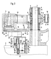
- the hinge column forming the first pivot axis 4 is fixed at the bottom in a holder 48 which is fixed to the machine frame 3 is screwed.
- the preform half 20 is hooked in on the left in FIG. 2, but not on the right in order to be able to show details of the rocker 19 and the preform pliers half 5.
- the mouth tools 22, 23 are not shown in FIG. 2. These mouth tools 22, 23 are blown radially freely with fluid through nozzle segments 49 and 50 with nozzle bores 51. The number, size and distribution of the nozzle bores 51 can be optimally adapted to achieve optimal cooling of the mouth tools 22, 23.
- the nozzle segments 49, 50 represent fluid outlets of the fluid distribution box 43.
- An insert 52 forming the feed channel 36 is inserted into the machine frame 3 for each half of the preforming pliers 5, 6.
- a valve flap 54 which can be pivoted about an axis 53.
- a bore 55 of the insert 52 receives a lower extension 56 of the second pivot axis 33, which is fixed therein by a screw 57.
- An intermediate plate 60 is screwed to an upper flange 58 of the insert 52 by screws 59 and receives both a collar 61 of the second pivot axis 33 and a flange 62 of a bushing 63 supporting the second pivot axis 33 in a bore.
- the flange 62 protrudes upward beyond the surface of the intermediate plate 60 and supports the first joint channel part 35 in such a way that a relatively small gap 64 is formed between the upper side of the intermediate plate 60 and a lower side of the first joint channel part 35.
- the loss of fluid through the gap 64 is negligibly small, particularly when the fluid pressure is relatively low.
- the inlet opening 37 of the first articulated duct part 35 is in constant communication via an interior 65 with an outlet opening 66 of the first articulated duct part 35 which is concentric with the third pivot axis 39.
- a bore 67 of the first articulated duct part 35 provides a lower one Passed end of the third pivot axis 39 and fixed therein by a self-locking nut 68.
- a collar 69 of the third pivot axis 39 lies on an upper side of the web 67.
- An upper side of the collar 69 carries a flange 70 of a bush 71 which supports an upper part of the third pivot axis 39.
- the second articulated channel part 41 is supported on an upper side of the flange 70 in such a way that there is a relatively small gap 72 between an upper side of the first articulated channel part 35 and a lower side of the second articulated channel part 41.
- a tube piece 74 which defines an inlet opening 73 of the second articulated channel part 41 and is coaxial with the third pivot axis 39, is inserted and secured therein with pins 75.
- the pipe section 74 projects downward into the outlet opening 66 and forms a circumferential, relatively small gap 76 with the latter.
- the inlet opening 73 is in constant communication via an interior space 77 with an outlet opening 79 defined by a pipe section 78 and coaxial with the fourth pivot axis 45.
- the pipe section 78 is secured by pins 80 with respect to the second articulated channel part 41 and projects into a coaxial with the fourth pivot axis 45 Inlet opening 81 of the fluid distribution box 43 in such a way that there is a relatively small annular gap 82 therebetween.
- a hollow cylindrical web 84 of the second articulated channel part 41 carries at the top a flange 85 of a bush 86, into which a drive extension 87 of the fourth pivot axis 45 engages.
- the fourth pivot axis 45 penetrates the fluid distribution box 43 and projects into a bore 88 in the preform pliers half 5, 6.
- the fourth pivot axis 45 is fixed in the axial direction by a snap ring 89 and a screw 90 and in the circumferential direction by a grub screw 91.
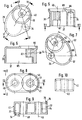
- first joint channel part 35 7 additionally shows the maximum pivoting angle 92 of the first articulated duct part 35 about the longitudinal axis 34.
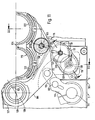
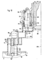
- FIG. 11 shows part of a finished mold side 100 of the station 2.
- the parisons pressed in the preform side (FIG. 1) are blown out into finished hollow glass objects in a manner known per se. This takes place in a molding tool 101 (FIGS. 12, 13 and 20) which, because of the double molding operation chosen, has two finished molds 102 in each case.
- Each finished mold 102 is equipped with finished mold halves 103, which can have different axial lengths depending on the hollow glass article to be produced.
- Each finished mold half 103 can be hooked into a rocker 104 which is pivotably articulated on a rocker pin 105 of a finished mold pliers half 106 and 107.
- the die halves 106, 107 are in turn pivoted about a hinge column that defines a first pivot axis 108 with a longitudinal axis 109 and is attached to the machine frame 3.
- the preforming pliers half 106 is drawn in the closed position and part of the preforming pliers half 107 in their fully open position by an angle 110.
- Each half of the finished pliers 106, 107 is connected via a bolt 111 to a tab 112 which is articulated on a crank pin 113 of a crank 115 fastened to a drive shaft 114.
- Fluid for cooling the mold 101 arrives at the machine frame 3 consolidated feed channel 116 into a first articulated channel part 117, from there into a second articulated channel part 118 and from there into a fluid distribution box 119, which is fastened with screws 120 to a collar 121 of the rocker pin 105.
- the fluid leaves the fluid distribution box 119 through a number of bores 122 and enters aligned bores 123 in the associated finished mold halves 103.
- the fluid finally leaves the bores 123 at the upper end of the finished mold halves 103 in the direction of an arrow 124.
- the first articulated duct part 117 can be pivoted about a second pivot axis 125, parallel to the first pivot axis 108 and fixed relative to the machine frame 3, with a longitudinal axis 126.
- the second joint channel part 118 can be pivoted about a third pivot axis 127 parallel to the second pivot axis 125 and mounted in the first joint channel part 117 with a longitudinal axis 128.
- the second articulated channel part 118 can also be pivoted about a fourth pivot axis 129 (FIG.
- the first joint channel part 117 and the second joint channel part 118 together form a connecting channel 131 for the fluid.
- a threaded extension 133 of the second pivot axis 125 is screwed into a web 132 of the insert 52 by means of an integrated nut 134.
- a flange 135 of a bush 136 which supports the second pivot axis 125 is supported on the nut 134.
- a hollow cylindrical web 137 of the first joint channel part 117 is supported on an upper side of the flange 135 in such a way that a relatively small gap 139 remains between an angle ring 138 inserted into the flange 58 and an annular inlet opening 140 of the first joint channel part 117.
- the inlet opening 140 is coaxial with the second pivot axis 125 and is continuously connected via an interior 141 to a likewise circular outlet opening 142 of the first articulated duct part 117.
- the outlet opening is coaxial with the third pivot axis 127.
- a flange 144 of a bush 145 which supports the third pivot axis 127 is supported on a hollow cylindrical web 143 of the first articulated duct cable 117.
- a collar 146 of the third pivot axis 127 rests on an upper side of the flange 144 such that a small gap 147 remains between an upper side of the first articulated channel part 117 and an underside of the second articulated channel part 118.
- annular inlet opening 148 of the second articulated channel part 118 Aligned with the outlet opening 142 is an annular inlet opening 148 of the second articulated channel part 118, which is continuously connected via an interior space 149 to an annular outlet opening 150 of the second articulated channel part 118.
- the outlet opening 150 is coaxial with the fourth pivot axis 129 and is delimited by a pipe section 151 inserted into the fluid distribution box 119 from below. There is a relatively small gap 152 between the fluid distribution box 119 and the pipe section 151 on the one hand and an edge of the second joint channel part 118 surrounding the outlet opening 150 on the other hand.
- the second joint channel part 118 is in contact with the self-locking nut 153 screwed onto a threaded end of the third pivot axis 127 Bund 146 held.
- a flange 155 of a bushing 156 mounted on the fourth pivot axis 129 is supported on a hollow cylindrical web 154 of the second articulated duct part 118.
- FIG. 13 finished mold halves 103 of shorter axial length are used. Since the insert 52 with its flange 58 should expediently not change its height during this change of shape, the angle ring 138 according to FIG. 12 is removed from its seat in the flange 58 and replaced by a tubular extension piece 157. 13, a second pivot axis 125, which is axially elongated in the area of the nut 134, is installed, so that the system of parts 117, 118 and 119 is raised to the new connection level to the shorter finished mold halves 103.
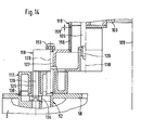
- Fig. 14 the same finished mold halves 103 are used as in Fig. 13.
- the space between the second joint duct part 118 and the fluid distribution box 119 is bridged by a tubular extension piece 158 after the pipe section 151 has been removed from the fluid distribution box 119 .
- the extension piece 158 is fixed with a slight interference fit in the second joint duct part 118 and forms a small gap 159 at the top with the fluid distribution box 119.
- the extension piece 158 could also be fixed to the fluid distribution box 119 instead of the pipe piece 151 and with the second joint duct part 118 one of the gap 152 form corresponding gap in FIG. 12. 14, the rocker pin 105 is extended downwards by the effective length of the extension piece 158.
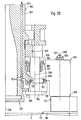
- FIG. 20 shows a finished mold half 103 of greater axial length in comparison with the finished mold half 103 in FIG. 12.
- the fluid passes from the first articulated channel part 117 into a special, essentially L-shaped second articulated channel part 160, which, in contrast to FIG. 12, flows from above into the fluid distribution box 119 feeds.
- the second joint channel part has a hollow cylindrical web 161, in which a bushing 162 mounted on the fourth pivot axis 129 is fastened by screws 163.
- the fourth pivot axis 129 extends downward through the fluid distribution box 119 and is provided at its lower end with a flange 164, on the top of which the fluid distribution box 119 is supported by screws 165.
Landscapes
- Engineering & Computer Science (AREA)
- Chemical & Material Sciences (AREA)
- Manufacturing & Machinery (AREA)
- Materials Engineering (AREA)
- Organic Chemistry (AREA)
- Moulds For Moulding Plastics Or The Like (AREA)
- Processing And Handling Of Plastics And Other Materials For Molding In General (AREA)
- Blow-Moulding Or Thermoforming Of Plastics Or The Like (AREA)
- Crystals, And After-Treatments Of Crystals (AREA)
- Saccharide Compounds (AREA)
- Drilling And Boring (AREA)
- Injection Moulding Of Plastics Or The Like (AREA)
- Air Conditioning Control Device (AREA)
- Adhesives Or Adhesive Processes (AREA)
- Casting Or Compression Moulding Of Plastics Or The Like (AREA)
- Encapsulation Of And Coatings For Semiconductor Or Solid State Devices (AREA)
- Heating, Cooling, Or Curing Plastics Or The Like In General (AREA)
- Devices That Are Associated With Refrigeration Equipment (AREA)
- Organic Low-Molecular-Weight Compounds And Preparation Thereof (AREA)
Priority Applications (1)
| Application Number | Priority Date | Filing Date | Title |
|---|---|---|---|
| AT81108062T ATE6144T1 (de) | 1980-10-25 | 1981-10-08 | Kuehlvorrichtung fuer ein formwerkzeug. |
Applications Claiming Priority (2)
| Application Number | Priority Date | Filing Date | Title |
|---|---|---|---|
| DE3040311 | 1980-10-25 | ||
| DE3040311A DE3040311C2 (de) | 1980-10-25 | 1980-10-25 | Kühlvorrichtung für ein Formwerkzeug |
Publications (2)
| Publication Number | Publication Date |
|---|---|
| EP0052223A1 EP0052223A1 (de) | 1982-05-26 |
| EP0052223B1 true EP0052223B1 (de) | 1984-02-08 |
Family
ID=6115182
Family Applications (1)
| Application Number | Title | Priority Date | Filing Date |
|---|---|---|---|
| EP81108062A Expired EP0052223B1 (de) | 1980-10-25 | 1981-10-08 | Kühlvorrichtung für ein Formwerkzeug |
Country Status (15)
| Country | Link |
|---|---|
| US (1) | US4361434A (cs) |
| EP (1) | EP0052223B1 (cs) |
| JP (1) | JPS5912609B2 (cs) |
| AT (1) | ATE6144T1 (cs) |
| AU (1) | AU540567B2 (cs) |
| BR (1) | BR8106919A (cs) |
| CA (1) | CA1168452A (cs) |
| CS (1) | CS236472B2 (cs) |
| DE (1) | DE3040311C2 (cs) |
| DK (1) | DK156560C (cs) |
| ES (1) | ES505692A0 (cs) |
| IE (1) | IE52483B1 (cs) |
| MX (1) | MX153708A (cs) |
| SU (1) | SU1103791A3 (cs) |
| ZA (1) | ZA817343B (cs) |
Families Citing this family (27)
| Publication number | Priority date | Publication date | Assignee | Title |
|---|---|---|---|---|
| WO1982002877A1 (en) * | 1981-02-27 | 1982-09-02 | Braithwaite David | Mould opening and closing mechanism |
| IN160666B (cs) * | 1982-09-03 | 1987-07-25 | Emhart Ind | |
| ZA836051B (en) * | 1982-09-03 | 1985-02-27 | Emhart Ind | Mould arrangement for glassware forming machine |
| GB8307462D0 (en) * | 1983-03-17 | 1983-04-27 | Emhart Ind | Mould for glassware forming machine |
| GB2137980B (en) * | 1983-04-08 | 1987-01-21 | Emhart Ind | Cooling glassware - forming moulds |
| DE3313934C1 (de) * | 1983-04-16 | 1984-04-19 | Heye Hermann Fa | Kuehlvorrichtung fuer ein Formwerkzeug zur Verarbeitung von Glas oder anderen thermoplastischen Stoffen |
| DE3336488A1 (de) * | 1983-10-07 | 1985-04-25 | Veba Glas Ag | Formwerkzeug fuer eine maschine zur verarbeitung schmelzfluessigen glases zu hohlglasartikeln |
| GB2152493B (en) * | 1984-01-12 | 1987-02-04 | Emhart Ind | Mould arrangement for use in cyclicly operated glassware forming machine |
| GB2154229B (en) * | 1984-01-25 | 1987-05-07 | Emhart Ind | Cooling arrangement for a mould of a glassware forming machine of the individual section type |
| GB2172591B (en) * | 1985-03-19 | 1988-07-13 | Emhart Ind | Mould opening and closing mechanism for a glassware forming machine |
| USRE34048E (en) * | 1986-05-05 | 1992-09-01 | I.M.T.E.C. Enterprises, Inc. | Cooling system for a glassware forming machine |
| US4750929A (en) * | 1987-02-03 | 1988-06-14 | Liberty Glass Company | Cooling system for a glassware forming machine |
| US4842637A (en) * | 1987-06-26 | 1989-06-27 | Glass Technology Development Corp. | Glassware forming machine with cooling system |
| US4909823A (en) * | 1989-05-30 | 1990-03-20 | Liberty Glass Company | Glassware forming machine with cooling system |
| US4983203A (en) * | 1990-01-17 | 1991-01-08 | American National Can Company | Cooling device for glass container forming machine |
| US5304229A (en) * | 1990-11-13 | 1994-04-19 | I.M.T.E.C. Enterprises, Inc. | Glassware forming machine with cooling system |
| DE4118682C1 (cs) * | 1991-06-07 | 1992-06-04 | Fa. Hermann Heye, 3063 Obernkirchen, De | |
| US5330551A (en) * | 1992-12-02 | 1994-07-19 | I.M.T.E.C. Enterprises, Inc. | Glassware forming machine with cooling system |
| US5358542A (en) * | 1992-12-09 | 1994-10-25 | American National Can Company | Glass container forming machine including neck ring mold cooling |
| US5656051A (en) * | 1993-06-14 | 1997-08-12 | Vidriera Monterrey, S.A. | Cooling method and mold arrangement for the manufacture of glass articles |
| US6442976B1 (en) | 2000-02-24 | 2002-09-03 | Owens-Brockway Glass Container Inc. | Liquid cooling of glassware molds |
| US6668591B2 (en) * | 2001-07-17 | 2003-12-30 | Owens-Brockway Plastic Products Inc. | Liquid cooling of glassware molds |
| US7596969B2 (en) * | 2003-04-28 | 2009-10-06 | Emhart Glass S.A. | Mold support mechanism for an I. S. machine |
| US7296442B2 (en) * | 2004-07-15 | 2007-11-20 | Owens-Brockway Glass Container Inc. | Neck ring cooling |
| FR2945979A1 (fr) * | 2009-05-29 | 2010-12-03 | Sidel Participations | Dispositif de moulage avec circuit(s) de fluide |
| US8316670B2 (en) * | 2010-04-21 | 2012-11-27 | Owens-Brockway Glass Container Inc. | Glassware mold cooling air supply |
| CN108124435B (zh) * | 2015-06-15 | 2020-05-12 | 西帕股份有限公司 | 用于吹制热塑性材料容器的吹制模具 |
Family Cites Families (10)
| Publication number | Priority date | Publication date | Assignee | Title |
|---|---|---|---|---|
| US2405475A (en) * | 1942-05-30 | 1946-08-06 | Raymond Gentil | Gas pump |
| US3094404A (en) * | 1958-03-24 | 1963-06-18 | Owens Illinois Glass Co | Mold assembly with controlled cooling |
| US3249418A (en) * | 1960-11-25 | 1966-05-03 | Owens Illinois Inc | Air operated neck molds |
| US3499746A (en) * | 1966-06-01 | 1970-03-10 | Anchor Hocking Corp | Air and water cooling of glassware forming machines |
| US3586491A (en) * | 1969-04-23 | 1971-06-22 | Owens Illinois Inc | Mold cooling apparatus for glass forming machine |
| US3653870A (en) * | 1970-03-09 | 1972-04-04 | Emhart Corp | Holding and cooling device for glassware molds |
| DE2114723C3 (de) * | 1971-03-26 | 1979-01-18 | Owens-Illinois, Inc., Toledo, Ohio (V.St.A.) | Vorrichtung zur Halterung und Kühlung mehrerer geteilter Glasformen |
| US3849101A (en) * | 1972-11-06 | 1974-11-19 | Emhart Corp | Cooling system for glass forming mold |
| US4009018A (en) * | 1975-07-07 | 1977-02-22 | Emhart Industries, Inc. | Glassware forming machine of the I. S. type with in-line mold motion |
| US4124884A (en) * | 1977-03-07 | 1978-11-07 | Bell Telephone Laboratories, Incorporated | DC to DC converter with regulated input impedance |
-
1980
- 1980-10-25 DE DE3040311A patent/DE3040311C2/de not_active Expired
-
1981
- 1981-09-22 ES ES505692A patent/ES505692A0/es active Granted
- 1981-09-23 US US06/304,976 patent/US4361434A/en not_active Expired - Lifetime
- 1981-09-28 DK DK429281A patent/DK156560C/da not_active IP Right Cessation
- 1981-09-29 AU AU75735/81A patent/AU540567B2/en not_active Ceased
- 1981-10-08 AT AT81108062T patent/ATE6144T1/de not_active IP Right Cessation
- 1981-10-08 EP EP81108062A patent/EP0052223B1/de not_active Expired
- 1981-10-15 CA CA000387950A patent/CA1168452A/en not_active Expired
- 1981-10-16 CS CS817617A patent/CS236472B2/cs unknown
- 1981-10-22 MX MX189766A patent/MX153708A/es unknown
- 1981-10-23 BR BR8106919A patent/BR8106919A/pt not_active IP Right Cessation
- 1981-10-23 ZA ZA817343A patent/ZA817343B/xx unknown
- 1981-10-23 SU SU813345904A patent/SU1103791A3/ru active
- 1981-10-23 IE IE2489/81A patent/IE52483B1/en not_active IP Right Cessation
- 1981-10-23 JP JP56169958A patent/JPS5912609B2/ja not_active Expired
Also Published As
| Publication number | Publication date |
|---|---|
| DE3040311A1 (de) | 1982-06-24 |
| ZA817343B (en) | 1982-10-27 |
| MX153708A (es) | 1986-12-22 |
| ES8207103A1 (es) | 1982-09-01 |
| DK429281A (da) | 1982-04-26 |
| CA1168452A (en) | 1984-06-05 |
| CS236472B2 (en) | 1985-05-15 |
| EP0052223A1 (de) | 1982-05-26 |
| AU7573581A (en) | 1982-05-06 |
| IE812489L (en) | 1982-04-25 |
| ATE6144T1 (de) | 1984-02-15 |
| DK156560C (da) | 1990-01-29 |
| BR8106919A (pt) | 1982-07-13 |
| DE3040311C2 (de) | 1982-09-16 |
| AU540567B2 (en) | 1984-11-22 |
| JPS5912609B2 (ja) | 1984-03-24 |
| SU1103791A3 (ru) | 1984-07-15 |
| US4361434A (en) | 1982-11-30 |
| JPS57135731A (en) | 1982-08-21 |
| ES505692A0 (es) | 1982-09-01 |
| IE52483B1 (en) | 1987-11-11 |
| DK156560B (da) | 1989-09-11 |
Similar Documents
| Publication | Publication Date | Title |
|---|---|---|
| EP0052223B1 (de) | Kühlvorrichtung für ein Formwerkzeug | |
| EP0050764B1 (de) | Druckfluidverteilvorrichtung zur Kühlung eines Formwerkzeugs zur Verarbeitung thermoplastischer Stoffe | |
| DE2623106C3 (de) | I.S. Glaswarenformmaschine mit geradliniger Bewegung der Formen | |
| DE3313934C1 (de) | Kuehlvorrichtung fuer ein Formwerkzeug zur Verarbeitung von Glas oder anderen thermoplastischen Stoffen | |
| DE69208082T2 (de) | Verfahren und Vorrichtung zum Kühlen einer Matrize | |
| WO2002034500A1 (de) | Blasmaschine mit an der blasvorrichtung angebrachten steuerventilen zur steuerung der blasluft | |
| DE3883312T2 (de) | Maschine zum Herstellen von Glasgegenständen. | |
| DE102007012779A1 (de) | Formkühlungssystem für IS-Maschine | |
| EP0311875A2 (de) | Verfahren und Vorrichtung zur Herstellung von Mehrschicht-Formteilen | |
| DE2840844C2 (de) | Verfahren zur Herstellung von Hohlgläsern nach dem Blas-Blas-Verfahren | |
| EP1377430B1 (de) | Vorrichtung zur herstellung von hohlkörpern aus kunststoff im extrusionsblasverfahren | |
| EP0542935B1 (de) | Vorrichtung zum kühlen der mündungsformen einer glasformmaschine | |
| DE69424206T2 (de) | Matrizkühlvorrichtung für eine Maschine zum Herstellen von Glasgegenstände | |
| DE3039312C2 (cs) | ||
| DE69104513T2 (de) | Kühlungen für Vorformen von Hohlglasmaschinen. | |
| DE69623136T2 (de) | Formkühlvorrichtung für die glasindustrie und verfahren zum herstellen und anpassen dieser kühlvorrichtung an verschiedenen formen | |
| DE69415451T2 (de) | Montagemittel für eine Vorformboden oder ähnliches in eine Maschine zum Herstellen von Glasgegenständen | |
| WO2018046114A1 (de) | Form- und mündungskühlungsanordnung für eine glasformmaschine | |
| DE69418766T2 (de) | Glaswaren-Formmaschine | |
| EP1423341B1 (de) | Verfahren und fertigformstation zum fertigblasen eines glasbehälters | |
| DE8028500U1 (de) | Kühlvorrichtung für ein Formwerkzeug | |
| DE818405C (de) | Glasformmaschine | |
| DE3040356C1 (de) | Vorrichtung zur Verteilung von Kuehlfluid ueber ein Formwerkzeug einer Maschine zur Verarbeitung von schmelzfluessigem Glas oder aehnlichen thermoplastischen Stoffen | |
| DE69614653T2 (de) | Vorrichtung zum Wegschieben von Glasgegenständen | |
| DE10052937A1 (de) | IS-Glasformungsmaschine |
Legal Events
| Date | Code | Title | Description |
|---|---|---|---|
| PUAI | Public reference made under article 153(3) epc to a published international application that has entered the european phase |
Free format text: ORIGINAL CODE: 0009012 |
|
| AK | Designated contracting states |
Designated state(s): AT BE CH FR GB IT LU NL SE |
|
| 17P | Request for examination filed |
Effective date: 19820402 |
|
| ITF | It: translation for a ep patent filed | ||
| GRAA | (expected) grant |
Free format text: ORIGINAL CODE: 0009210 |
|
| AK | Designated contracting states |
Designated state(s): AT BE CH FR GB IT LI LU NL SE |
|
| REF | Corresponds to: |
Ref document number: 6144 Country of ref document: AT Date of ref document: 19840215 Kind code of ref document: T |
|
| ET | Fr: translation filed | ||
| PLBE | No opposition filed within time limit |
Free format text: ORIGINAL CODE: 0009261 |
|
| STAA | Information on the status of an ep patent application or granted ep patent |
Free format text: STATUS: NO OPPOSITION FILED WITHIN TIME LIMIT |
|
| 26N | No opposition filed | ||
| PGFP | Annual fee paid to national office [announced via postgrant information from national office to epo] |
Ref country code: LU Payment date: 19920826 Year of fee payment: 12 |
|
| PGFP | Annual fee paid to national office [announced via postgrant information from national office to epo] |
Ref country code: AT Payment date: 19921030 Year of fee payment: 12 |
|
| ITTA | It: last paid annual fee | ||
| EPTA | Lu: last paid annual fee | ||
| PG25 | Lapsed in a contracting state [announced via postgrant information from national office to epo] |
Ref country code: LU Free format text: LAPSE BECAUSE OF NON-PAYMENT OF DUE FEES Effective date: 19931008 Ref country code: AT Effective date: 19931008 |
|
| PGFP | Annual fee paid to national office [announced via postgrant information from national office to epo] |
Ref country code: CH Payment date: 19941004 Year of fee payment: 14 |
|
| PGFP | Annual fee paid to national office [announced via postgrant information from national office to epo] |
Ref country code: NL Payment date: 19941031 Year of fee payment: 14 |
|
| PGFP | Annual fee paid to national office [announced via postgrant information from national office to epo] |
Ref country code: BE Payment date: 19941110 Year of fee payment: 14 |
|
| EAL | Se: european patent in force in sweden |
Ref document number: 81108062.1 |
|
| PG25 | Lapsed in a contracting state [announced via postgrant information from national office to epo] |
Ref country code: LI Effective date: 19951031 Ref country code: CH Effective date: 19951031 Ref country code: BE Effective date: 19951031 |
|
| BERE | Be: lapsed |
Owner name: HEYE HERMANN Effective date: 19951031 |
|
| PG25 | Lapsed in a contracting state [announced via postgrant information from national office to epo] |
Ref country code: NL Effective date: 19960501 |
|
| REG | Reference to a national code |
Ref country code: CH Ref legal event code: PL |
|
| NLV4 | Nl: lapsed or anulled due to non-payment of the annual fee |
Effective date: 19960501 |
|
| PGFP | Annual fee paid to national office [announced via postgrant information from national office to epo] |
Ref country code: SE Payment date: 19970908 Year of fee payment: 17 |
|
| PGFP | Annual fee paid to national office [announced via postgrant information from national office to epo] |
Ref country code: GB Payment date: 19970929 Year of fee payment: 17 |
|
| PGFP | Annual fee paid to national office [announced via postgrant information from national office to epo] |
Ref country code: FR Payment date: 19970930 Year of fee payment: 17 |
|
| PG25 | Lapsed in a contracting state [announced via postgrant information from national office to epo] |
Ref country code: GB Free format text: LAPSE BECAUSE OF NON-PAYMENT OF DUE FEES Effective date: 19981008 |
|
| PG25 | Lapsed in a contracting state [announced via postgrant information from national office to epo] |
Ref country code: SE Free format text: LAPSE BECAUSE OF NON-PAYMENT OF DUE FEES Effective date: 19981009 |
|
| GBPC | Gb: european patent ceased through non-payment of renewal fee |
Effective date: 19981008 |
|
| EUG | Se: european patent has lapsed |
Ref document number: 81108062.1 |
|
| PG25 | Lapsed in a contracting state [announced via postgrant information from national office to epo] |
Ref country code: FR Free format text: LAPSE BECAUSE OF NON-PAYMENT OF DUE FEES Effective date: 19990630 |
|
| REG | Reference to a national code |
Ref country code: FR Ref legal event code: ST |