EP0052025B1 - Dispositif de fixation d'un élément amovible, en particulier d'un cabochon de voyant lumineux, dans un réceptacle - Google Patents
Dispositif de fixation d'un élément amovible, en particulier d'un cabochon de voyant lumineux, dans un réceptacle Download PDFInfo
- Publication number
- EP0052025B1 EP0052025B1 EP19810401553 EP81401553A EP0052025B1 EP 0052025 B1 EP0052025 B1 EP 0052025B1 EP 19810401553 EP19810401553 EP 19810401553 EP 81401553 A EP81401553 A EP 81401553A EP 0052025 B1 EP0052025 B1 EP 0052025B1
- Authority
- EP
- European Patent Office
- Prior art keywords
- receptacle
- tongue
- recess
- removable element
- wall
- Prior art date
- Legal status (The legal status is an assumption and is not a legal conclusion. Google has not performed a legal analysis and makes no representation as to the accuracy of the status listed.)
- Expired
Links
Images
Classifications
-
- H—ELECTRICITY
- H05—ELECTRIC TECHNIQUES NOT OTHERWISE PROVIDED FOR
- H05K—PRINTED CIRCUITS; CASINGS OR CONSTRUCTIONAL DETAILS OF ELECTRIC APPARATUS; MANUFACTURE OF ASSEMBLAGES OF ELECTRICAL COMPONENTS
- H05K7/00—Constructional details common to different types of electric apparatus
- H05K7/02—Arrangements of circuit components or wiring on supporting structure
- H05K7/12—Resilient or clamping means for holding component to structure
-
- H—ELECTRICITY
- H05—ELECTRIC TECHNIQUES NOT OTHERWISE PROVIDED FOR
- H05K—PRINTED CIRCUITS; CASINGS OR CONSTRUCTIONAL DETAILS OF ELECTRIC APPARATUS; MANUFACTURE OF ASSEMBLAGES OF ELECTRICAL COMPONENTS
- H05K5/00—Casings, cabinets or drawers for electric apparatus
- H05K5/02—Details
- H05K5/0204—Mounting supporting structures on the outside of casings
Definitions
- the invention relates to a device for fixing a removable element in a receptacle, in particular a light indicator cap in a receptacle mounted on a panel, the element introduced into the receptacle being urged therein. sense of its ejection by organs. elastic contained in the receptacle, such as spring contact pistons intended to supply electrical power to bulbs placed in a cabochon.
- elastic contained in the receptacle such as spring contact pistons intended to supply electrical power to bulbs placed in a cabochon.
- Such devices are known for example from document FR-A-2389214.
- the invention aims to create a device of this kind, capable of holding the removable element in its receptacle where it is subjected to the action of said elastic members which tend to eject it, retaining the removable element in front be able to be easily removed to allow it to be ejected from the receptacle.
- This device must also be simple and occupy a negligible volume.
- the device which is the subject of the present invention is characterized in that it comprises an elastic tongue integral with the wall of the receptacle and projecting obliquely inside of it in a direction such that said tongue s' elastically erases the passage of the removable element when it is introduced into the receptacle, then substantially resumes its natural position by entering a recess made in the adjacent wall of the removable element and then retaining the latter by the abutment effect of its end against the rear edge of said recess, while a clearance is provided between the adjacent walls of the receptacle and of the removable element, making it possible to introduce a blade between them so as to be erased using this blade said tab and thus release the removable element, which is then ejected from the receptacle by said elastic members.
- the recess of the removable element is advantageously a blind recess, that is to say it has the shape of a bowl having a bottom and edges. It preferably has a rectangular outline.
- the longitudinal dimension of the recess, counted in the direction of introduction of the removable element into the receptacle, is such that it allows an additional insertion of the removable element beyond its position of retention by the tongue, which is useful for the possible control of electrical contacts incorporated in the receptacle.
- the elastic locking tab can be attached to the wall of the receptacle. It is then preferably fixed on the outer face of the latter and emerges inside the receptacle through a window made in said wall.
- the tongue can also be an integral part of the wall of the receptacle and be produced by cutting and bending a part of it.
- the shape of the removable element is arbitrary; it suffices that it can slide into its receptacle.
- the fastening device according to the invention is distinguished by its simplicity, its small size (the general dimensions of the removable element and of the receptacle being hardly modified), its reliability with respect to mechanical influences (shocks and vibrations). and its ease of use.
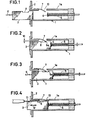
- Figures 1 to 4 show in longitudinal section a removable element and its receptacle incorporating a fixing device according to the invention, the removable element being respectively at the start of the insertion stroke in the receptacle, in normal fixing position, in position sinking, additional and being ejected from the receptacle.
- a receptacle 1 cyclindric or prismatic fixed to a panel 2 and intended to receive a removable element 3 constituted here by a lens holder cabochon whose light bulbs are powered, when it has taken its position normal in the receptacle 1 (FIG. 2), by movable pistons 4 associated with springs 5.
- the bulbs and the pistons 4 are in any number.
- the installation in the receptacle 1 of the lens 3 is done by introducing the latter by pushing along arrow 6 (FIG. 1), on the side of the panel 2 opposite to that where the receptacle 1 is located.
- an elastic tongue 7 which projects obliquely inside the receptacle 1 and had disappeared when the cabochon 3 passed towards the wall 1a of the receptacle 1 to which it is fixed, resumes * substantially its natural position and engages in a recess 8 in the form of a rectangular bowl provided by the cabochon 3.
- This tongue 7 then retains by snap-fastening and locks the cabochon 3, the rear edge 8a of the recess 8 of the latter abutting the end of the tongue 7 under the force of the springs 5.
- Figure 3 shows that the bowl 8 has a length such that it does not oppose an additional depression of the cap 3 under a new thrust (arrow 9) against the action of the springs 5, for example in the purpose of controlling electrical contacts (not shown) in the manner of a push button.
- the cap returns to its normal position (FIG. 2) under the return action of the springs 5.
- 1 has tab 7, of curved shape, is fixed, for example by welding, on the outer face of the wall 1a of the receptacle 1, and emerges inside the latter through a window 13 formed in this wall, a window in which the tongue 7 can slide away under the action of the blade 11 of the unlocking tool.
- the shape of the cross section of the cap 3 and the associated receptacle 1 can be any, for example square, rectangular or circular.
Landscapes
- Engineering & Computer Science (AREA)
- Microelectronics & Electronic Packaging (AREA)
- Fastening Of Light Sources Or Lamp Holders (AREA)
- Details Of Connecting Devices For Male And Female Coupling (AREA)
Description
- L'invention se rapporte à un dispositif de fixation d'un élément amovible dans un réceptacle, en particulier d'un cabochon de voyant lumineux dans un réceptacle monté sur un panneau, l'élément introduit dans le réceptacle s'y trouvant sollicité dans le sens de son éjection par des organes . élastiques que contient le réceptacle, tels que des pistons de contact à ressort destinés à assurer l'alimentation électrique d'ampoules placées dans un cabochon. De tels dispositifs sont connus par exemple du document FR-A-2389214.
- L'invention a pour but de créer un dispositif de ce genre, capable de maintenir l'élément amovible dans son réceptacle où il est soumis à l'action desdites organes élastiques qui tendent à l'éjecter, la retenue de l'élément amovible devant pouvoir être aisément supprimée pour permettre son éjection hors du réceptacle. Ce dispositif doit de plus être simple et occuper un volume négligeable.
- Le dispositif qui fait l'objet de la présente invention est caractérisé par le fait qu'il comprend une languette élastique solidaire de la paroi du réceptacle et faisant saillie obliquement à l'intérieur de celui-ci suivant une direction telle que ladite languette s'efface élastiquement au passage de l'élément amovible lorsqu'il est introduit dans le réceptacle, puis reprend sensiblement sa position naturelle en pénétrant dans un évidement pratiqué dans la paroi adjacente de l'élément amovible et en retenant alors ce dernier par effet de butée de son extrémité contre le bord postérieur dudit évidement, tandis qu'un jeu est prévu entre les parois adjacentes du réceptacle et de l'élément amovible, permettant d'introduire entre celles-ci une lame pour faire s'effacer à l'aide de cette lame ladite languette et libérer ainsi l'élément amovible, qui est alors éjecté du réceptacle par lesdits organes élastiques.
- L'évidement de l'élément amovible est avantageusement un évidement borgne, c'est-à-dire qu'il présente la forme d'une cuvette comportant un fond et des bords. Il a de préférence un contour rectangulaire.
- Dans une forme d'exécution préférée, la dimension longitudinale de l'évidement, comptée dans la direction d'introduction de l'élément amovible dans le réceptacle, est telle qu'elle y permet un enfoncement supplémentaire de l'élément amovible au delà de sa position de retenue par la languette, ce qui est utile pour la commande éventuelle de contacts électriques incorporés au réceptacle.
- La languette élastique de verrouillage peut être rapportée sur la paroi du réceptacle. Elle est alors de préférence fixée sur la face extérieure de celle-ci et émerge à l'intérieur du réceptacle par une fenêtre pratiquée dans ladite paroi. La languette peut aussi faire partie intégrante de la paroi du réceptacle et être réalisée par découpage et cambrage d'une partie de celle-ci.
- La forme de l'élément amovible est quelconque; il suffit qu'il puisse pénétrer par coulissement dans son réceptacle.
- Le dispositif de fixation selon l'invention se distingue par sa simplicité, son faible encombrement (les dimensions générales de l'élément amovible et du réceptacle étant à peine modifiées), sa fiabilité vis-à-vis des influences mécaniques (chocs et vibrations) et sa facilité d'utilisation.
- La description qui va suivre, en regard des dessins annexés à titre d'exemple non limitatif, permettra de bien comprendre comment l'invention peut être mise en pratique.
- Les figures 1 à 4 représentent en coupe longitudinale un élément amovible et son réceptacle incorporant un dispositif de fixation selon l'invention, l'élément amovible étant respectivement en début de course d'introduction dans le réceptacle, en position de fixation normale, en position d'enfoncement, supplémentaire et en cours d'éjection hors du réceptacle.
- On voit sur les figures un réceptacle 1 cyclindri- que ou prismatique fixé à un panneau 2 et destiné à recevoir un élément amovible 3 constitué ici par un cabochon portelampes de voyant lumineux, dont les ampoules électrique sont alimentées, lorsqu'il a pris sa position normale dans le réceptacle 1 (figure 2), par des pistons mobiles 4 associés à des ressorts 5. Les ampoules et les pistons 4 sont en nombre quelconque.
- La mise en place dans le réceptacle 1 du cabochon 3 se fait en introduisant celui-ci par poussée suivant la flèche 6 (figure 1 ), du côté du panneau 2 opposé à celui où se trouve le réceptacle 1. Vers la fin de la course d'introduction du carbochon 3, celui-ci rencontre les pistons 4 qui reculent élastiquement en exerçant une contre-poussée.
- Lorsque le cabochon a atteint sa position normale (figure 2), une languette élastique 7, qui s'avance obliquement à l'intérieur du réceptacle 1 et s'était effacée au passage du cabochon 3 vers la paroi 1 a du réceptacle 1 à laquelle elle est fixée, reprend* sensiblement sa position naturelle et s'engage dans un évidement 8 en forme de cuvette rectangulaire qu'offre le cabochon 3. Cette languette 7 retient alors par encliquetage et verrouille le cabochon 3, le bord postérieur 8a de l'évidement 8 de ce dernier butant contre l'extrémité de la languette 7 sous l'effort des ressorts 5.
- La figure 3 montre que la cuvette 8 a une longueur telle qu'elle ne s'oppose pas à un enfoncement supplémentaire du cabochon 3 sous une nouvelle poussée (flèche 9) à l'encontre de l'action des ressorts 5, par exemple dans le but de commander des contacts électriques (non représentés) à la manière d'un bouton-poussoir. A la cessation de la poussée 9, le cabochon revient dans sa position normale (figure 2) sous l'action de rappel des ressorts 5.
- Si l'on désire ôter le cabochon 3 de son réceptacle 1, il suffit d'introduire entre la paroi 1 a de celui-ci et le cabochon 3, grâce à un jeu 10 prévu à cet effet (figure 2), la lame 11 d'un outil de déverrouillage (figure 4) qui fait sortir la languette 7 de la cuvette 8 et libère le cabochon 3, lequel est éjecté suivant la flèche 12 par la détente des ressorts 5.
- Dans la forme d'exécution représentée, 1 a languette 7, de forme incurvée, est fixée, par exemple par soudure, à la face extérieure de la paroi la du réceptacle 1, et émerge à l'intérieur de ce dernier à travers une fenêtre 13 pratiquée dans cette paroi, fenêtre dans laquelle la languette 7 peut s'éclipser sous l'action de la lame 11 de l'outil de déverrouillage.
- La forme de la section droite du cabochon 3 et du réceptacle 1 associé peut être quelconque, par exemple carrée, rectangulaire ou circulaire.
Claims (6)
Applications Claiming Priority (2)
| Application Number | Priority Date | Filing Date | Title |
|---|---|---|---|
| FR8023646A FR2493665A1 (fr) | 1980-11-05 | 1980-11-05 | Dispositif de fixation d'un element amovible, en particulier d'un cabochon de voyant lumineux, dans un receptacle |
| FR8023646 | 1980-11-05 |
Publications (2)
| Publication Number | Publication Date |
|---|---|
| EP0052025A1 EP0052025A1 (fr) | 1982-05-19 |
| EP0052025B1 true EP0052025B1 (fr) | 1985-01-16 |
Family
ID=9247700
Family Applications (1)
| Application Number | Title | Priority Date | Filing Date |
|---|---|---|---|
| EP19810401553 Expired EP0052025B1 (fr) | 1980-11-05 | 1981-10-07 | Dispositif de fixation d'un élément amovible, en particulier d'un cabochon de voyant lumineux, dans un réceptacle |
Country Status (3)
| Country | Link |
|---|---|
| EP (1) | EP0052025B1 (fr) |
| DE (1) | DE3168354D1 (fr) |
| FR (1) | FR2493665A1 (fr) |
Cited By (1)
| Publication number | Priority date | Publication date | Assignee | Title |
|---|---|---|---|---|
| DE102006008796B3 (de) * | 2006-02-24 | 2007-12-27 | Interactive Wear Ag | Fixiervorrichtung mit integrierter Elektronikkomponente |
Families Citing this family (3)
| Publication number | Priority date | Publication date | Assignee | Title |
|---|---|---|---|---|
| FI88242C (fi) * | 1989-02-24 | 1993-04-13 | Nokia Mobira Oy | Monteringsanordning foer transistorer eller andra vaermeutvecklande komponenter |
| WO2012011982A2 (fr) * | 2010-04-07 | 2012-01-26 | The Wiremold Company | Systèmes de bus personnalisable |
| US9640960B2 (en) | 2010-04-07 | 2017-05-02 | The Wiremold Company | Customizable bus systems |
Family Cites Families (3)
| Publication number | Priority date | Publication date | Assignee | Title |
|---|---|---|---|---|
| FR2315783A1 (fr) * | 1975-06-25 | 1977-01-21 | Russenberger Sa Ets | Porte-lampe temoin interchangeable pour circuit electrique |
| FR2340018A1 (fr) * | 1976-01-29 | 1977-08-26 | Alsthom Cgee | Systeme mecanique de support de cartes de circuits imprimes |
| IT1094110B (it) * | 1977-04-29 | 1985-07-26 | Rau Swf Autozubehoer | Dispositivo di fissaggio per interruttori |
-
1980
- 1980-11-05 FR FR8023646A patent/FR2493665A1/fr active Granted
-
1981
- 1981-10-07 EP EP19810401553 patent/EP0052025B1/fr not_active Expired
- 1981-10-07 DE DE8181401553T patent/DE3168354D1/de not_active Expired
Cited By (1)
| Publication number | Priority date | Publication date | Assignee | Title |
|---|---|---|---|---|
| DE102006008796B3 (de) * | 2006-02-24 | 2007-12-27 | Interactive Wear Ag | Fixiervorrichtung mit integrierter Elektronikkomponente |
Also Published As
| Publication number | Publication date |
|---|---|
| EP0052025A1 (fr) | 1982-05-19 |
| DE3168354D1 (en) | 1985-02-28 |
| FR2493665B1 (fr) | 1982-12-17 |
| FR2493665A1 (fr) | 1982-05-07 |
Similar Documents
| Publication | Publication Date | Title |
|---|---|---|
| EP0634252B1 (fr) | Couteau de poche à lame verrouillable comprenant un moyen de déverrouillage à bouton-poussoir | |
| FR2656904A1 (fr) | Mecanisme de blocage a liberation rapide. | |
| FR2504180A1 (fr) | Serrure a pene dormant | |
| BE1000835A5 (fr) | Support de montage adaptable sur une arme a main. | |
| EP0052025B1 (fr) | Dispositif de fixation d'un élément amovible, en particulier d'un cabochon de voyant lumineux, dans un réceptacle | |
| FR2565867A1 (fr) | Dispositif d'ebavurage | |
| FR2498740A1 (fr) | Allumeur piezo-electrique du type a percussion et bouton-poussoir | |
| EP0133068A1 (fr) | Fermoir de sécurité | |
| EP1005958B1 (fr) | Appareil de fixation de tampon par gaz comprimé | |
| WO2005058553A1 (fr) | Dispositif de retenue d’une clavette d’outil pour appareil de demolition a percussion | |
| CH685680A5 (fr) | Outil de coupe à plaquettes amovibles. | |
| FR2832663A1 (fr) | Outil de scellement portatif actionne par combustion interne pour elements de fixation | |
| EP0342070A1 (fr) | Dispositif de manoeuvre du mécanisme de clipsage des appareils électriques modulaires | |
| FR2827137A1 (fr) | Dispositif pour maintenir dans n'importe quelle position en particulier sur un vetement porte avec une fonction anti-perte une paire de lunettes | |
| FR2524357A1 (fr) | Ensemble de sectionnement a charge explosive | |
| EP1321707A1 (fr) | Support de fixation, notamment pour luminaire encastrable | |
| FR2486173A1 (fr) | Dispositif de fixation pour appareils a encastrer | |
| FR2700356A1 (fr) | Dispositif de fixation du corps d'une serrure dans un ajour d'une tôle. | |
| FR2882284A1 (fr) | Mecanisme pour le verrouillage d'un outil de racloir | |
| EP0785326B1 (fr) | Pène demi-tour pour serrure réversible et serrure réversible comportant un tel pène | |
| FR2622495A1 (fr) | Appareil de scellement a extracteur perfectionne | |
| FR2585979A1 (fr) | Cutter a changement de lame par l'avant | |
| FR2546676A1 (fr) | Dispositif de visualisation de l'enfichage de connecteurs electriques sur un plateau avionique | |
| EP0947404A1 (fr) | Fourreau de lance de lavage | |
| FR2598673A1 (fr) | Emplanture d'aileron ejectable pour planche de surf et planche a voile |
Legal Events
| Date | Code | Title | Description |
|---|---|---|---|
| PUAI | Public reference made under article 153(3) epc to a published international application that has entered the european phase |
Free format text: ORIGINAL CODE: 0009012 |
|
| 17P | Request for examination filed |
Effective date: 19811102 |
|
| AK | Designated contracting states |
Designated state(s): DE GB IT NL |
|
| ITCL | It: translation for ep claims filed |
Representative=s name: BARZANO' E ZANARDO MILANO S.P.A. |
|
| TCNL | Nl: translation of patent claims filed | ||
| ITF | It: translation for a ep patent filed |
Owner name: BARZANO' E ZANARDO MILANO S.P.A. |
|
| GRAA | (expected) grant |
Free format text: ORIGINAL CODE: 0009210 |
|
| AK | Designated contracting states |
Designated state(s): DE GB IT NL |
|
| REF | Corresponds to: |
Ref document number: 3168354 Country of ref document: DE Date of ref document: 19850228 |
|
| PLBE | No opposition filed within time limit |
Free format text: ORIGINAL CODE: 0009261 |
|
| STAA | Information on the status of an ep patent application or granted ep patent |
Free format text: STATUS: NO OPPOSITION FILED WITHIN TIME LIMIT |
|
| 26N | No opposition filed | ||
| ITTA | It: last paid annual fee | ||
| PGFP | Annual fee paid to national office [announced via postgrant information from national office to epo] |
Ref country code: GB Payment date: 19921007 Year of fee payment: 12 |
|
| PGFP | Annual fee paid to national office [announced via postgrant information from national office to epo] |
Ref country code: NL Payment date: 19921031 Year of fee payment: 12 |
|
| PGFP | Annual fee paid to national office [announced via postgrant information from national office to epo] |
Ref country code: DE Payment date: 19921211 Year of fee payment: 12 |
|
| PG25 | Lapsed in a contracting state [announced via postgrant information from national office to epo] |
Ref country code: GB Effective date: 19931007 |
|
| PG25 | Lapsed in a contracting state [announced via postgrant information from national office to epo] |
Ref country code: NL Effective date: 19940501 |
|
| GBPC | Gb: european patent ceased through non-payment of renewal fee |
Effective date: 19931007 |
|
| NLV4 | Nl: lapsed or anulled due to non-payment of the annual fee | ||
| PG25 | Lapsed in a contracting state [announced via postgrant information from national office to epo] |
Ref country code: DE Effective date: 19940701 |