EP0051430B1 - X-ray apparatus - Google Patents
X-ray apparatus Download PDFInfo
- Publication number
- EP0051430B1 EP0051430B1 EP81305079A EP81305079A EP0051430B1 EP 0051430 B1 EP0051430 B1 EP 0051430B1 EP 81305079 A EP81305079 A EP 81305079A EP 81305079 A EP81305079 A EP 81305079A EP 0051430 B1 EP0051430 B1 EP 0051430B1
- Authority
- EP
- European Patent Office
- Prior art keywords
- ray
- cinecameras
- mirror
- ray tube
- mode
- Prior art date
- Legal status (The legal status is an assumption and is not a legal conclusion. Google has not performed a legal analysis and makes no representation as to the accuracy of the status listed.)
- Expired
Links
- 230000003287 optical effect Effects 0.000 claims description 41
- 238000002594 fluoroscopy Methods 0.000 claims description 7
- 230000001360 synchronised effect Effects 0.000 claims description 4
- 230000005855 radiation Effects 0.000 claims description 2
- 238000002310 reflectometry Methods 0.000 claims description 2
- 238000002601 radiography Methods 0.000 description 7
- 238000002583 angiography Methods 0.000 description 3
- 238000010438 heat treatment Methods 0.000 description 3
- 238000010586 diagram Methods 0.000 description 2
- 230000002526 effect on cardiovascular system Effects 0.000 description 2
- 200000000007 Arterial disease Diseases 0.000 description 1
- 208000002330 Congenital Heart Defects Diseases 0.000 description 1
- 208000002564 X-linked cardiac valvular dysplasia Diseases 0.000 description 1
- 208000028922 artery disease Diseases 0.000 description 1
- 210000000748 cardiovascular system Anatomy 0.000 description 1
- 208000028831 congenital heart disease Diseases 0.000 description 1
- 238000001514 detection method Methods 0.000 description 1
- 238000003745 diagnosis Methods 0.000 description 1
- 238000010894 electron beam technology Methods 0.000 description 1
- 210000002767 hepatic artery Anatomy 0.000 description 1
- 230000002093 peripheral effect Effects 0.000 description 1
- 238000004846 x-ray emission Methods 0.000 description 1
Images

Classifications
-
- A—HUMAN NECESSITIES
- A61—MEDICAL OR VETERINARY SCIENCE; HYGIENE
- A61B—DIAGNOSIS; SURGERY; IDENTIFICATION
- A61B6/00—Apparatus or devices for radiation diagnosis; Apparatus or devices for radiation diagnosis combined with radiation therapy equipment
-
- G—PHYSICS
- G03—PHOTOGRAPHY; CINEMATOGRAPHY; ANALOGOUS TECHNIQUES USING WAVES OTHER THAN OPTICAL WAVES; ELECTROGRAPHY; HOLOGRAPHY
- G03B—APPARATUS OR ARRANGEMENTS FOR TAKING PHOTOGRAPHS OR FOR PROJECTING OR VIEWING THEM; APPARATUS OR ARRANGEMENTS EMPLOYING ANALOGOUS TECHNIQUES USING WAVES OTHER THAN OPTICAL WAVES; ACCESSORIES THEREFOR
- G03B42/00—Obtaining records using waves other than optical waves; Visualisation of such records by using optical means
- G03B42/02—Obtaining records using waves other than optical waves; Visualisation of such records by using optical means using X-rays
-
- H—ELECTRICITY
- H01—ELECTRIC ELEMENTS
- H01J—ELECTRIC DISCHARGE TUBES OR DISCHARGE LAMPS
- H01J35/00—X-ray tubes
- H01J35/02—Details
- H01J35/04—Electrodes ; Mutual position thereof; Constructional adaptations therefor
- H01J35/045—Electrodes for controlling the current of the cathode ray, e.g. control grids
-
- H—ELECTRICITY
- H01—ELECTRIC ELEMENTS
- H01J—ELECTRIC DISCHARGE TUBES OR DISCHARGE LAMPS
- H01J35/00—X-ray tubes
- H01J35/24—Tubes wherein the point of impact of the cathode ray on the anode or anticathode is movable relative to the surface thereof
-
- H—ELECTRICITY
- H05—ELECTRIC TECHNIQUES NOT OTHERWISE PROVIDED FOR
- H05G—X-RAY TECHNIQUE
- H05G1/00—X-ray apparatus involving X-ray tubes; Circuits therefor
- H05G1/08—Electrical details
- H05G1/58—Switching arrangements for changing-over from one mode of operation to another, e.g. from radioscopy to radiography, from radioscopy to irradiation or from one tube voltage to another
-
- H—ELECTRICITY
- H05—ELECTRIC TECHNIQUES NOT OTHERWISE PROVIDED FOR
- H05G—X-RAY TECHNIQUE
- H05G1/00—X-ray apparatus involving X-ray tubes; Circuits therefor
- H05G1/08—Electrical details
- H05G1/60—Circuit arrangements for obtaining a series of X-ray photographs or for X-ray cinematography
-
- H—ELECTRICITY
- H01—ELECTRIC ELEMENTS
- H01J—ELECTRIC DISCHARGE TUBES OR DISCHARGE LAMPS
- H01J2235/00—X-ray tubes
- H01J2235/06—Cathode assembly
- H01J2235/068—Multi-cathode assembly
Definitions
- This invention relates to X-ray apparatus and is aimed at providing such apparatus capable of performing stereoscopic, or mono-scopic X-ray cinematography, or X-ray fluoroscopy.
- an X-ray apparatus for stereoscopic cinematography designed to radiate X-rays from two points independently, the apparatus comprising a converter for converting an X-ray image derived by means of X-rays to an optical image; an optical system for projecting the optical image including a half mirror, first and second cinecameras arranged to receive the optical image when the half mirror is in operative position, means for synchronising the drives of the cinecameras so that their shutters are opened alternatively and so that the shutters are never open simultaneously and a switching controller which is designed to control that X-rays are radiated from the points alternatively in synchronisation with the alternatively open shutters of the cinecameras.
- an X-ray apparatus for stereoscopic cinematography comprising means alternatively emitting X-rays from two points, a converter, an optical system, a cinecamera and a television camera, also arranged to receive the optical image projected by the optical system.
- a stereoscopic X-ray device employing an X-ray tube designed to radiate X-rays from at least two focal points independently.
- an X-ray tube designed to radiate X-rays independently from at least two focal points is employed with an optical system for independently projecting images derived from those focal points, so that stereographs may be obtained.
- the present invention provides X-ray apparatus employing an X-ray tube designed to radiate X-rays from at least two focal points independently, the apparatus comprising a converter for converting an X-ray image derived by means of X-rays from the tube to an optical image; an optical system for projecting the optical image, the system including a first half-mirror and a second half-mirror which is arranged to receive light from the location of the first half-mirror, each of the half-mirrors being movable between an operative position in the light path and an inoperative position out of the light path; first and second cinecameras arranged to receive the optical image when the first half-mirror and second half-mirror respectively is in operative position the half-mirrors having reflectivities such that about the same quantum of light is transmitted to both cinecameras; means for synchronising the drives of the cinecameras so that their shutters are opened alternatively and so that the shutters are never open simultaneously; a television camera also arranged
- half-mirror a mirror which is part-transmissive and part-reflective.
- an X-ray tube 1 for stereoscopic radiography has a conical trapezoid shaped rotating anode P, and two cathodes Kr and KI spaced apart by a distance corresponding to the average human inter-ocular distance, and facing the oblique part of anode P.
- the suffixes r and I are in conjunction with the reference numerals of the drawings relate to the right and left eyes, respectively.
- Grids Gr and GI are interposed between the cathodes Kr and KI and the rotating anode P and are employed for X-ray exposure control.
- the potentials on the two grids are alternately altered to cause X-ray radiation alternatively from the corresponding anode parts during the times when electrons are emitted from the respective cathodes KI and Kr.
- the two beams of electrons from the cathodes impinge upon the portions of the oblique anode P facing the cathodes, to define two focal points fl and fr from which a pair of X-ray beams are radiated. In this way, two X-ray beams are generated, spaced laterally at the inter-ocular distance.
- the X-ray tube 1 as described above is disclosed in U.S. Patent No. 4287420, for example.
- An object 2 such as a patient is interposed between the X-ray tube 1 and an image intensifier 3 which receives on its input face the X-ray beams after passing through the object 2, and forms light images.
- Optical system 4 is connected to the output of intensifier 3 and projects the optical output image as will be described.
- Cinecameras 5 and 6 are attached to the sides of the optical system 4 to photograph optical images directed thereto to the optical system.
- the cinecameras 5 and 6 are synchronously driven, so that their shutters open alternately, and so that the shutters are never open together.
- each shutter is formed by a disc having a window at a given angular position; by rotating the shutter one image per frame is photographed on the cinefilm, the movement of which is synchronised with the shutter movement.
- Cinecameras 5 and 6 issue a series of shutter motion detection signals when their shutters are open, the outputs being employed for exposure control of the X-ray tube 1.
- a television camera 7 converts the optical image from the intensifier 3 to an electrical image signal and it delivers the latter signal to a television monitor (not shown).
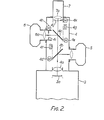
- the optical system 4 and its peripherals are shown in detail in Figure 2.
- the optical system consists of a lightproof enclosure attached to the image intensifier 3 and having a lens 4a adjacent to the outward face 3a of the intensifier 3.
- Television camera 7 with its lens 7a is attached to the other end of the enclosure, coaxially with lens 4a.
- Cinecameras 5 and 6 are attached to opposite sides of the optical system 4 and at different distances from lens 4a; their optical axes are at right angles to the axis of lens 4a.
- Half-mirrors 4b and 4c are mounted within the enclosure and opposite the respective cinecameras 5 and 6.
- Each half-mirror 4b or 4c can be moved by a motor 4d or 4e respectively between an operative position shown in full line, in which the half-mirror lies at an angle of 45° to the axis of lens 4a, and an inoperative position shown in chain line in which the half-mirror lies parallel to, and spaced from, the optical axis.
- each half-mirror When in its operative position, each half-mirror is effective to deflect a part of the incident light to the associated cinecamera.
- Half-mirror 4b pertaining to cinecamera 5 is 50% reflective and 50% transmissive, while half-mirror 4c pertaining to cinecamera 6 is 90% reflective and 10% transmissive.
- Position detectors 4f and 4g are located in the neighbourhood of the half-mirrors 4b and 4c and detect whether the respective half-mirror is in its operative position or in its inoperative position.
- An optical diaphragm 4i is driven by a motor 4h to control the amount of incident light to lens 6a of cinecamera 6, and compensates for movement of half-mirror 4b: when half-mirror is moved into its inoperative position, diaphragm 4i is operated to decrease the incident light, and vice versa.
- Diaphragm 4i may be constituted by the cinecamera's own diaphragm, provided that the latter can be externally controlled.
- a second optical diaphragm 4j is provided to control the quantum of light to television camera 7 and is driven by motor 4k in accordance with the positions of half-mirrors 4b and 4c, in the manner of diaphragm 4i.
- a mode selector 8 determines the mode in which the apparatus is to operate, i.e. whether in the stereoscopic cinematography mode, the mono-scopic cinematography mode or the fluoroscopy mode.
- a radiographic control device 9 which receives signals from selector 8, the cinecamera shutter drives and the detectors 4f and 4g controls the motors 4d, 4e, 4h and 4k, the drives of cinecameras 5 and 6 when stereoscopy mode is selected, the drive of cinecamera 6 only when the mono-scopic mode is selected, and the X-ray tube 1.
- An X-ray controller 10 controlled by control device 9 emits signals to X-ray high voltage generator 11 to set the X-ray tube voltage and current according to whether the fluoroscopy mode or the radiographic mode is selected.
- controller 10 emits signals to X-ray switching controller 12 which in turn controls the emission of the beams from the focal points fr and fl.
- the "right" beam from focal point fr is generated when the shutter of cinecamera 5 is open and the "left" X-ray beam from focal point fl is generated when the shutter of cinecamera 6 is open.
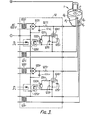
- the X-ray tube switching controller 12 is shown in greater detail in Figure 3, in which the signs + and - designate input terminals which receive respectively the positive and negative high voltage outputs from the generator 11. Controller 12 includes two identical control circuits, one for the "right” X-ray beam and the other for the "left” X-ray beam. As the two circuits are identical, only one will be described, although both are shown in Figure 3 with the suffixes r and I.
- a filament heating transformer 121 receives an output from generator 11 and generates a heating voltage corresponding to its input, that voltage being applied to the corresponding cathode K of the X-ray tube 1.
- Transformer 122 for producing a grid potential is connected to a power source and generates a variable voltage at its output.
- Rectifier circuit 123 performs full rectification to obtain a d.c. voltage of negative polarity.
- Tetrode 124 for the exposure switching control of the X-ray tube is connected between the corresponding grid and cathode of the X-ray tube 1.
- a power supply source 125 is connected between the cathode and second grid of tetrode 124 and applies to the second grid a positive bias to bring the internal resistance of the tetrode to an optimum value.
- Condenser 126 is connected between the output terminals of the rectifier circuit 123 and a resistor 127 is connected between the rectifying circuit 123 and the corresponding grid of tube 1.
- Potential source 128 is connected between the cathode and first grid of tetrode 124 to bias negatively the first grid to an optimum value.
- a photo-coupler 129 is rendered active on receipt of the X-ray exposure switching control output from controller 10 and its output activates a switching transistor 130 having its emitter connected to the negative terminal of potential source 128 through resistor 131 and its collector to the positive terminal of that source.
- the high voltage output from generator 11 is applied between the anode and the cathodes of tube 1, being applied to the cathodes through the filament heating transformers 121.
- the negative potential of rectifying circuit 123 is applied to the respective grid of tube 1 through resistor 127, and the positive potential to the respective cathode, so as to apply negative bias to the grid G and to hold the tube 1 in the cut-off state.
- the output voltage of rectifying circuit 123 is supplied to tetrode 124 as the tube voltage, the tetrode is inversely biased between its primary grid and cathode and is normally in its cut-off state.
- photo-coupler 129 receives a control output from controller 10
- transistor 130 is rendered conducting, to close the loop formed by bias source 128, transistor 130, and resistor 131.
- the resulting voltage drop across resistor 131 increases the potential on the first grid of tetrode 124 and the tetrode is rendered conducting.
- transistor 130 When the input to the photo-coupler 129 disappears, transistor 130 is rendered non-conducting causing tetrode 124 to be cut-off. Negative bias is again applied to the respective grid K of tube 1 and the X-ray beam from the corresponding focal point of the anode ceases. In this way, it is possible to control the X-ray exposures corresponding to the right and left eyes by controlling the photo-couplers 129r and 1291 by the X-ray controllers 10.
- Selector 8 applies an appropriate instruction to control device 9 which, in turn, controls motors 4d and 4e as required to move the half-mirrors 4b and 4c into the optical path, as shown in full line in Figure 2; the control of the two motors is determined by the outputs of the detectors 4f and 4g, so that each motor is operated only if the respective half-mirror is in the inoperative position.
- a control output is also applied from control device 9 to each of the motors 4h and 4k to open the diaphragms 4i and 4j to their settings corresponding to the half-mirrors being in their operative positions. In this way, the optical system 4 is set for stereoscopic cinematography.
- X-ray controller 10 under the control of a further signal from control device 9, sets the tube voltage and current for radiography.
- a drive signal is delivered to cenecameras 5 and 6 to initiate shutter movement and film movement.
- the shutters of the two cinecameras are displaced by 180°, so that when the shutter of one is open, that of the other is closed.
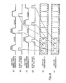
- Indication signals synchronised with the shutter opening times of cinecameras 5 and 6 are issued to control device 9, as shown in Figures 4(a) and 4(c) respectively.
- Control device 9 generates X-ray exposure switching output signals in synchronism with the signals from the cinecameras.
- cinecamera 5 is to receive images corresponding to the right eye and cinecamera 6 images corresponding to the left eye
- control device 9 transmits an X-ray exposure switching control output to controller 10, which sends a signal to the photo-coupler 129r in the X-ray tube switching controller 12. That results in an X-ray beam being emitted from focal point fr of the X-ray tube 1, as described above; the pulses of X-ray emissions from point fr are shown in Figure 4(b).
- the resulting X-ray image of the object is received on the input face of intensifier 3 and is converted to an optical image which is directed to the optical system 4. 50% of the light is diverted by half-mirror 4b to cinecamera 5, which records the right-eye pictures of the object 2 as shown in Figure 4(e).
- the 50% of the incident light transmitted by half-mirror 4b is received by the second half-mirror 4c which diverts 90% towards cinecamera 6, i.e. 45% of the initial quantum of light transmitted from the intensifier 3. However, as cinecamera 6 has its shutter closed, no exposure is made.
- the light transmitted through mirror 4c (5% of the initial quantum) is received by television camera 7 which displays the image on the monitor.
- the resulting indication signals from the cinecameras results in photo-coupler 129r being cut off and photo-coupler 1291 being rendered inactive, so that the "right" X-ray beam from focal point fr is cut off and the "left” X-ray beam from focal point fl is initiated.
- the resulting light beam is diverted by half mirrors 4b and 4c as before but, in this case, the shutter of cinecamera 5 is closed so that no exposure is made, whereas the shutter of cinecamera 6 is open and photographs the "left" pictures of the object.
- Television camera 7 again receives and displays the light transmitted by half-mirror 4c.
- cinecameras 5 and 6 produce "right” and “left” pictures of the object, which can be viewed subsequently in a stereoscope to obtain a three-dimensional view of the object.
- control device causes half-mirror 4b to be moved into the inoperative position shown in chain in Figure 2.
- Signals are applied to the motors 4h and 4k to adjust diaphragms 4i and 4j to alter the opening settings to values corresponding to the increased quantum of light reaching half-mirror 4c, due to half-mirror 4b being rendered inoperative.
- only cinecamera 6 is actuated and only the "left" grid GI positively biased in order to cause pulses of X-ray to be emitted from focal point fl.
- the operation is otherwise as described above in relation to stereoscopic radiography, it being understood that half-mirror 4c transmits 90% of the initial light to cinecamera 6 and 10% to television camera 7.
- the amounts of light received through the shutter of cinecamera 6 is however compensated by diaphragm 4i, while diaphragm 4j of the television camera has a similar function.
- Control device 9 delivers signals to motors 4d and 4e to bring both half-mirrors to their inoperative positions, if they are not already so positioned.
- optical diaphragm 4j of television camera 7 is adjusted to compensate for the increased amount of light passing towards the television camera.
- X-ray controller 10 is controlled to set the voltage and current of tube 1 to the values for fluoroscopy.
- a signal for positively biasing the "right" grid Gr is applied to X-ray tube switching controller 12 from controller 10 to cause the X-ray beam to be emitted from focal point fr.
- the resulting X-ray image is converted by intensifier 3 to an optical image, which is led to television camera 7 to display it on the monitor.
Landscapes
- Health & Medical Sciences (AREA)
- Life Sciences & Earth Sciences (AREA)
- Physics & Mathematics (AREA)
- Medical Informatics (AREA)
- General Physics & Mathematics (AREA)
- Engineering & Computer Science (AREA)
- Pathology (AREA)
- Surgery (AREA)
- Nuclear Medicine, Radiotherapy & Molecular Imaging (AREA)
- Optics & Photonics (AREA)
- Biophysics (AREA)
- Radiology & Medical Imaging (AREA)
- Biomedical Technology (AREA)
- Heart & Thoracic Surgery (AREA)
- Molecular Biology (AREA)
- High Energy & Nuclear Physics (AREA)
- Animal Behavior & Ethology (AREA)
- General Health & Medical Sciences (AREA)
- Public Health (AREA)
- Veterinary Medicine (AREA)
- Apparatus For Radiation Diagnosis (AREA)
- X-Ray Techniques (AREA)
- Radiography Using Non-Light Waves (AREA)
Applications Claiming Priority (2)
| Application Number | Priority Date | Filing Date | Title |
|---|---|---|---|
| JP152668/80 | 1980-10-30 | ||
| JP55152668A JPS5776800A (en) | 1980-10-30 | 1980-10-30 | X-ray cinematographic stereographic unit |
Publications (2)
| Publication Number | Publication Date |
|---|---|
| EP0051430A1 EP0051430A1 (en) | 1982-05-12 |
| EP0051430B1 true EP0051430B1 (en) | 1985-07-24 |
Family
ID=15545479
Family Applications (1)
| Application Number | Title | Priority Date | Filing Date |
|---|---|---|---|
| EP81305079A Expired EP0051430B1 (en) | 1980-10-30 | 1981-10-27 | X-ray apparatus |
Country Status (5)
| Country | Link |
|---|---|
| US (1) | US4413352A (cg-RX-API-DMAC7.html) |
| EP (1) | EP0051430B1 (cg-RX-API-DMAC7.html) |
| JP (1) | JPS5776800A (cg-RX-API-DMAC7.html) |
| KR (1) | KR850001491B1 (cg-RX-API-DMAC7.html) |
| DE (1) | DE3171503D1 (cg-RX-API-DMAC7.html) |
Families Citing this family (20)
| Publication number | Priority date | Publication date | Assignee | Title |
|---|---|---|---|---|
| JPS607292A (ja) * | 1983-06-27 | 1985-01-16 | Toshiba Corp | 立体x線テレビ装置 |
| US4677477A (en) * | 1985-08-08 | 1987-06-30 | Picker International, Inc. | Television camera control in radiation imaging |
| DE8710425U1 (de) * | 1987-07-29 | 1988-11-24 | Siemens AG, 1000 Berlin und 8000 München | Lichtverteiler für eine Röntgendiagnostikeinrichtung |
| DE8806828U1 (de) * | 1988-05-25 | 1988-09-01 | Siemens AG, 1000 Berlin und 8000 München | Lichtverteiler für eine Röntgendiagnostikeinrichtung |
| FR2634094B1 (fr) * | 1988-07-05 | 1992-04-10 | Gen Electric Cgr | Appareil a rayons x a visualisation de la geometrie du faisceau de rayons x |
| EP0374298A1 (de) * | 1988-12-23 | 1990-06-27 | Siemens Aktiengesellschaft | Lichtverteiler für ein Röntgendiagnostikgerät |
| US5127394A (en) * | 1989-06-26 | 1992-07-07 | Tilane Corporation | Fluoroscopy switching device |
| US4993404A (en) * | 1989-06-26 | 1991-02-19 | Lane Timothy G | Fluoroscopy switching device |
| US5107528A (en) * | 1989-11-13 | 1992-04-21 | Kabushiki Kaisha Toshiba | X-ray diagnosis apparatus |
| US5233639A (en) * | 1990-11-29 | 1993-08-03 | Marks Lloyd A | Stereoscopic fluoroscopy apparatus and method of producing stereoscopic X-ray images |
| US6368269B1 (en) | 1993-05-20 | 2002-04-09 | Tilane Corporation | Apparatus for concurrent actuation of multiple foot pedal operated switches |
| US5455707A (en) * | 1993-07-30 | 1995-10-03 | Ion Laser Technology | Apparatus and method for light beam multiplexing |
| EP0761060B1 (en) * | 1995-03-21 | 2000-01-26 | Koninklijke Philips Electronics N.V. | Image pick-up apparatus |
| UA22127C2 (uk) * | 1996-09-10 | 1998-04-30 | Сергій Іванович Мірошніченко | Телевізійhа система високої розрізhяльhої здатhості |
| WO2007142999A2 (en) * | 2006-05-31 | 2007-12-13 | L-3 Communications Security And Detection Systems, Inc. | Dual energy x-ray source |
| CN101347335B (zh) * | 2007-03-14 | 2010-11-03 | 张迎光 | 能产生立体视觉效果的x射线发生装置及医用x射线设备 |
| US9142381B2 (en) | 2009-06-17 | 2015-09-22 | Koninklijke Philips N.V. | X-ray tube for generating two focal spots and medical device comprising same |
| US9079078B2 (en) | 2011-12-29 | 2015-07-14 | Taylor Made Golf Company, Inc. | Golf club head |
| US10016662B1 (en) | 2014-05-21 | 2018-07-10 | Taylor Made Golf Company, Inc. | Golf club |
| US10290460B2 (en) | 2016-09-07 | 2019-05-14 | General Electric Company | X-ray tube with gridding electrode |
Family Cites Families (8)
| Publication number | Priority date | Publication date | Assignee | Title |
|---|---|---|---|---|
| US3244878A (en) * | 1963-09-19 | 1966-04-05 | Stevenson | Stereoscopic X-ray examination apparatus with light conductive rods to transmit the optical images |
| US3424901A (en) * | 1965-02-01 | 1969-01-28 | Philips Corp | Stereoscopic x-ray apparatus |
| US3432658A (en) * | 1966-05-26 | 1969-03-11 | Gen Electric | Stereoscopic x-ray apparatus employing image converting and polarizing means |
| DE1262772B (de) * | 1967-03-15 | 1968-03-07 | C H F Mueller G M B H | Verfahren und Vorrichtung fuer Stereo-Roentgen-Kinematographie |
| US3684354A (en) * | 1970-10-30 | 1972-08-15 | Gen Electric | Image gate |
| DE2062430A1 (de) * | 1970-12-18 | 1972-07-06 | Siemens Ag | Röntgendiagnostikeinrichtung zur Anfertigung von Röntgenstereofilmen |
| JPS586264B2 (ja) * | 1978-11-02 | 1983-02-03 | 株式会社東芝 | ステレオ用x線管 |
| JPS5788446A (en) * | 1980-11-20 | 1982-06-02 | Toshiba Corp | X-ray cine-stereo photographing device |
-
1980
- 1980-10-30 JP JP55152668A patent/JPS5776800A/ja active Granted
-
1981
- 1981-10-27 DE DE8181305079T patent/DE3171503D1/de not_active Expired
- 1981-10-27 EP EP81305079A patent/EP0051430B1/en not_active Expired
- 1981-10-30 KR KR1019810004170A patent/KR850001491B1/ko not_active Expired
- 1981-10-30 US US06/316,674 patent/US4413352A/en not_active Expired - Fee Related
Also Published As
| Publication number | Publication date |
|---|---|
| DE3171503D1 (en) | 1985-08-29 |
| JPS639359B2 (cg-RX-API-DMAC7.html) | 1988-02-27 |
| JPS5776800A (en) | 1982-05-13 |
| KR850001491B1 (ko) | 1985-10-11 |
| US4413352A (en) | 1983-11-01 |
| EP0051430A1 (en) | 1982-05-12 |
| KR830007054A (ko) | 1983-10-14 |
Similar Documents
| Publication | Publication Date | Title |
|---|---|---|
| EP0051430B1 (en) | X-ray apparatus | |
| EP0052995B1 (en) | X-ray apparatus | |
| EP0088356B1 (en) | X-ray diagnostic apparatus | |
| US4737972A (en) | Stereoscopic fluoroscope arrangement | |
| US3546461A (en) | Automatic control of a nonsynchronous cine fluororadiographic apparatus | |
| JPS646596B2 (cg-RX-API-DMAC7.html) | ||
| GB2132460A (en) | X-ray apparatus and method | |
| EP0206156A2 (en) | X-ray imaging system | |
| US4058833A (en) | Radiation imaging apparatus and method | |
| US2972681A (en) | Cinefluorographic apparatus | |
| US4649558A (en) | X-ray diagnostic system with an image intensifier television chain | |
| US4335311A (en) | X-ray diagnostic apparatus with an image-intensifier TV chain | |
| US4119856A (en) | X-ray diagnostic apparatus for producing series exposures | |
| US3440422A (en) | Biplane x-ray image system | |
| JPS58195545A (ja) | X線絞り装置 | |
| US4109151A (en) | Dual filament x-ray tube used in production of fluoroscopic images | |
| JPH01246796A (ja) | X線検査装置 | |
| JPS5840542A (ja) | X線シネ・ステレオ装置 | |
| JPH05237080A (ja) | X線撮影装置 | |
| JPS62102738A (ja) | X線立体視装置 | |
| Zarnstorff et al. | Stereoscopic fluoroscopy and stereographic cineangiocardiography | |
| JPH0145367B2 (cg-RX-API-DMAC7.html) | ||
| JPS62227319A (ja) | X線立体視装置 | |
| JPH025334A (ja) | X線装置 | |
| JPS6113941A (ja) | スライス位置表示装置 |
Legal Events
| Date | Code | Title | Description |
|---|---|---|---|
| PUAI | Public reference made under article 153(3) epc to a published international application that has entered the european phase |
Free format text: ORIGINAL CODE: 0009012 |
|
| AK | Designated contracting states |
Designated state(s): DE FR GB IT NL |
|
| 17P | Request for examination filed |
Effective date: 19821015 |
|
| RAP1 | Party data changed (applicant data changed or rights of an application transferred) |
Owner name: KABUSHIKI KAISHA TOSHIBA |
|
| GRAA | (expected) grant |
Free format text: ORIGINAL CODE: 0009210 |
|
| AK | Designated contracting states |
Designated state(s): DE FR GB IT NL |
|
| PG25 | Lapsed in a contracting state [announced via postgrant information from national office to epo] |
Ref country code: IT Free format text: LAPSE BECAUSE OF FAILURE TO SUBMIT A TRANSLATION OF THE DESCRIPTION OR TO PAY THE FEE WITHIN THE PRESCRIBED TIME-LIMIT;WARNING: LAPSES OF ITALIAN PATENTS WITH EFFECTIVE DATE BEFORE 2007 MAY HAVE OCCURRED AT ANY TIME BEFORE 2007. THE CORRECT EFFECTIVE DATE MAY BE DIFFERENT FROM THE ONE RECORDED. Effective date: 19850724 |
|
| REF | Corresponds to: |
Ref document number: 3171503 Country of ref document: DE Date of ref document: 19850829 |
|
| ET | Fr: translation filed | ||
| PLBE | No opposition filed within time limit |
Free format text: ORIGINAL CODE: 0009261 |
|
| STAA | Information on the status of an ep patent application or granted ep patent |
Free format text: STATUS: NO OPPOSITION FILED WITHIN TIME LIMIT |
|
| 26N | No opposition filed | ||
| REG | Reference to a national code |
Ref country code: GB Ref legal event code: 746 |
|
| PGFP | Annual fee paid to national office [announced via postgrant information from national office to epo] |
Ref country code: NL Payment date: 19871031 Year of fee payment: 7 |
|
| PG25 | Lapsed in a contracting state [announced via postgrant information from national office to epo] |
Ref country code: GB Effective date: 19881027 |
|
| PG25 | Lapsed in a contracting state [announced via postgrant information from national office to epo] |
Ref country code: NL Effective date: 19890501 |
|
| NLV4 | Nl: lapsed or anulled due to non-payment of the annual fee | ||
| PG25 | Lapsed in a contracting state [announced via postgrant information from national office to epo] |
Ref country code: FR Free format text: LAPSE BECAUSE OF NON-PAYMENT OF DUE FEES Effective date: 19890630 |
|
| PG25 | Lapsed in a contracting state [announced via postgrant information from national office to epo] |
Ref country code: DE Effective date: 19890701 |
|
| GBPC | Gb: european patent ceased through non-payment of renewal fee | ||
| REG | Reference to a national code |
Ref country code: FR Ref legal event code: ST |