EP0051243B1 - Device for dumping trash containers provided with a device for opening the container closure - Google Patents
Device for dumping trash containers provided with a device for opening the container closure Download PDFInfo
- Publication number
- EP0051243B1 EP0051243B1 EP81108944A EP81108944A EP0051243B1 EP 0051243 B1 EP0051243 B1 EP 0051243B1 EP 81108944 A EP81108944 A EP 81108944A EP 81108944 A EP81108944 A EP 81108944A EP 0051243 B1 EP0051243 B1 EP 0051243B1
- Authority
- EP
- European Patent Office
- Prior art keywords
- guide
- guide loop
- container
- opening
- loop
- Prior art date
- Legal status (The legal status is an assumption and is not a legal conclusion. Google has not performed a legal analysis and makes no representation as to the accuracy of the status listed.)
- Expired
Links
Images

Classifications
-
- B—PERFORMING OPERATIONS; TRANSPORTING
- B65—CONVEYING; PACKING; STORING; HANDLING THIN OR FILAMENTARY MATERIAL
- B65F—GATHERING OR REMOVAL OF DOMESTIC OR LIKE REFUSE
- B65F3/00—Vehicles particularly adapted for collecting refuse
- B65F3/02—Vehicles particularly adapted for collecting refuse with means for discharging refuse receptacles thereinto
- B65F3/12—Conjoint motion of lids, flaps, and shutters on vehicle and on receptacle; Operation of closures on vehicle conjointly with tipping of receptacle
Definitions
- the invention relates to a pouring device for garbage containers at a garbage collection point, in particular at a garbage truck, with the movable catch arms receiving the garbage container and with a device for opening the lid of the garbage container, consisting of a guideway for a stop pin, pin or bolt attached to the side of the lid. projection which can be brought into engagement during the lifting and / or tilting movement of the guideway.
- the invention has for its object to provide a pouring device for garbage containers of the type mentioned in the preamble of the main claim, in which the lid of garbage containers of different sizes with one and the same device can be opened and closed automatically by a positive guide during the lifting movement.
- the guide track has a guide loop: and can be moved in a controlled manner with respect to the refuse collection point in a track plane of the cover depending on the movement of the catch arms.
- a rectangular pouring opening 1 on a garbage truck, not shown, is surrounded by a frame 2, the upper part 3 of which connects to a vertical part 4 and which is closed by a lower frame part 5.
- a tilting shaft 6 is attached to the frame 2 and has catch arms 7 on both sides. Since only one opening device is shown on one side of the pouring device, the second catch arm is also not shown. However, it is assumed that the pouring device on the frame part opposite the frame part 4 is provided with a mirror image opening device, as is generally designated 10.
- the opening device 10 has a curved guide track 11 with a guide loop 12, the areas of curvature of which are described in more detail below.
- a rod 13 is articulated on the outside of the catch arm 7 and is connected to a link 15 via a joint 14.
- the respective free ends 16 and 17 of the rod 13 and the link 15 are provided with holes in order to increase or decrease the leverage effect when pivoting the opening device 10, which is described in more detail below.
- the pouring device 1 and thus also the opening device 10 in the embodiment shown are primarily placed on the so-called 1.1 m3 waste containers; a part of such a large waste container 20 is shown in Fig.2.
- This refuse container has a rectangular cross section and a hinge 22 on one side of the fuselage 21, on which in turn a lid 23 is articulated.
- the cover 23 has one side 24, in the vicinity of its front edge, a stop pin 25; A corresponding stop bolt can also be provided on the side of the cover 23 opposite the side 24.
- FIG. 3 shows a 1.1 m 3 large waste container 30, on the trunk part 31 of which a pivot cover 32 is provided which can be pivoted about bolts 33 arranged on the opposite sides of the trunk part.
- the waste container is inserted into the catch arms 40 in a conventional manner, in such a way that the suspension bolts 26 on the container 20 or 36 on the container 30 into the opening 41 of the Catch arms arranged in mirror image and connected to the tilting shaft 6 are used.
- a tilting chair can usually be provided; However, it can also be attached to a hanging bar.
- the stop pin 25 comes into contact with the guide rail formed at the lower end of the guide track 11; 6, this guide rail is provided with an L-shaped cross-section, so that its leg 42 ensures that the stop pin 25 cannot deflect laterally.
- the stop pin During the initial lifting movement of the waste container, the stop pin "rolls" on the guide rail in a slightly convexly curved starting area, as can be seen from FIG. 4.
- the guide loop 12 has a U-shaped cross section throughout, as it is e.g. can be seen from Fig. 7 or Fig. 8.
- the two legs 50 and 51 ensure that the stop pin 25 does not leave its positive guidance and that, in the embodiment of the refuse container according to FIG. 2, the lid assumes a tilted position indicated in FIG. 5. This reliably avoids that the lid is a hindrance when emptying waste.
- the cross-sectional widening according to FIG. 5 in the guide loop 12 serves to ensure that when the container 20 is tilted, its suspension bolts 26 can slide down in the longitudinal slots 45, as can be seen in FIG. 5, so that the container 20 in the tilted position is also secured by the catch arms 40 is held. Since a relative sinking of the waste container in the longitudinal slots 45 is brought about by changing the position of the suspension bolts 26, the forced guidance for the stop blocks 25 must also be able to follow this movement, for which purpose the bulge 46 in the guide loop 12 serves.
- the guide loop 12 and the associated guide rail is attached to the frame 2 of the garbage truck in such a way that the entire opening device can be pivoted about a joint 64.
- the linkage 13, 14, 15 is provided in the embodiment shown. Depending on the tilting movement of the catch arm 40, this handlebar linkage causes the opening device 11, 12 to pivot about the articulation point 64.
- the opening device 11, 12 is pivoted faster than the tilting movement of the refuse container. Decisive for this is on the one hand the distance of the articulation point 62 from the axis of rotation 63 of the tilting shaft 6 and on the other hand the effective length of the link 15 between its articulation point 64 and the articulation point 14.
- the lid 23 is forcibly opened by the opening device and the positive guidance of the stop pin 25, the Opening angle in this case is approximately 250 °.
- the opening device i.e. thus the guide track 11 with the guide loop 12 and the guide rail is pivoted by approximately 90 °.
- the opening device described can be used for almost all types of refuse containers, and in particular for refuse containers which have a rectilinear inlay bar or a rectilinear hanging bar.
- the opening device can also be used with round garbage cans, in which case, however, the stop pin or stop projection should be attached to the widest part of the lid.
Abstract
Description
Die Erfindung betrifft eine Schüttvorrichtung für Müllbehälter an einer Müllsammelstelle, insbesondere an einem Müllwagen, mit den Müllbehälter aufnehmenden, bewegbaren Fangarmen und mit einer Vorrichtung zum Öffnen des Deckels des Müllbehälters, bestehend aus einer Führungsbahn für einen seitlich am Deckel angebrachten Anschlagstift, -bolzen oder - vorsprung, der während der Hubund/oder Kippbewegung der Führungsbahn in Eingriff bringbar ist.The invention relates to a pouring device for garbage containers at a garbage collection point, in particular at a garbage truck, with the movable catch arms receiving the garbage container and with a device for opening the lid of the garbage container, consisting of a guideway for a stop pin, pin or bolt attached to the side of the lid. projection which can be brought into engagement during the lifting and / or tilting movement of the guideway.
Aus der DE-OS 26 27 949 ist eine solche Schüttvorrichtung zum Entleeren von Müllgefäßen in Sammelbehälter (insbesondere mittels Transportwagen) bekannt, die sowohl mit zweiteiligen Schiebe- Klappdeckelbehältern als auch mit Schwenkdeckelbehältern beschickt werden kann. Für jede dieser Behälterarten ist eine eigene Öffnungsvorrichtung erforderlich. Die jeweiligen Führungsbahnen an der Schüttvorrichtung sind dabei starr an der Schüttöffnung festgelegt. Sollen Behälter vom Typ, wie er im ersten Ausführungsbeispiel dieser Schrift dargestellt ist, mit gleicher Breite, jedoch verschiedener Größe verwendet werden, so sind Führungsschienen in unterschiedlicher Höhe erforderlich.From DE-OS 26 27 949 such a pouring device for emptying waste containers in collecting containers (in particular by means of transport trolleys) is known, which can be loaded with two-part sliding hinged-lid containers as well as with swivel-lid containers. A separate opening device is required for each of these types of containers. The respective guideways on the pouring device are rigidly fixed to the pouring opening. If containers of the type shown in the first embodiment of this document are to be used with the same width but different sizes, guide rails of different heights are required.
Der Erfindung liegt die Aufgabe zugrunde, eine Schüttvorrichtung für Müllbehälter des im Oberbegriff des Hauptanspruchs genannten Typs zu schaffen, bei der der Deckel von Müllbehältern unterschiedlicher Größe mit ein und derselben Vorrichtung durch eine Zwangsführung während der Hubbewegung selbsttätig geöffnet und geschlossen werden kann.The invention has for its object to provide a pouring device for garbage containers of the type mentioned in the preamble of the main claim, in which the lid of garbage containers of different sizes with one and the same device can be opened and closed automatically by a positive guide during the lifting movement.
Die Aufgabe wird erfindungsgemäß dadurch gelöst, daß die Führungsbahn eine Führungsschleife aufweis: und bezüglich der Müllsammelstelle in einer Bahnebene des Deckels abhängig von der Eewegung der Fangarme gesteuert bewegbar ist.The object is achieved in that the guide track has a guide loop: and can be moved in a controlled manner with respect to the refuse collection point in a track plane of the cover depending on the movement of the catch arms.
Aus der DE-PS 478 938 ist eine Vorrichtung zur staubfreien Entleerung von mit Scharnierdeckeln versehenen Müllgefäßen im Sammelbehälter bekannt, bei der jedoch an der Schüttöffnung ein Hilfsdeckel vorgesehen ist, an der der Deckel des Müllbehälters befestigt wird. Dieser Hilfsdeckel ist fest mit einer Führungsbahn installiert, die starr an der Schüttvorrichtung angeordnet ist. Nachteilig ist auch, daß bei dieser bekannten Vorrichtung nur ein Behältertyp verwendet werden kann. Bei der erfindungsgemäßen Vorrichtung hingegen können unterschiedliche Behältergrößen, soweit sie in der Breite übereinstimmen verwendet werden, da infolge der gesteuerten Bewegbarkeit der Führungsbahn auch große Behälter, soweit sie die Auslegung der Schüttöffnung nicht überschreiten, entleert werden können.Die die Zwangsöffnung im letzten Stadium bewirkende Führungsschleife führt den Deckel in einer nahezu eiförmigen Bewegung, wobei jedoch kein geschlossener Kreislauf stattfindet, vielmehr ist der am Deckel angebrachte Anschlagstift durch eine Trennwand daran gehindert, nach Durchlaufen der Schleife in einer Richtung wieder in den im wesentlichen geraden Bereich der Führungsbahn einzutreten, vielmehr ist er gezwungen, bei der Absetzbewegung des Behälters die Führungsschleife wieder in umgekehrter Richtung zu durchlaufen.From DE-PS 478 938 a device for dust-free emptying of waste containers provided with hinged lids in the collecting container is known, but in which an auxiliary lid is provided at the dump opening, to which the lid of the waste container is attached. This auxiliary cover is permanently installed with a guide track which is rigidly arranged on the pouring device. Another disadvantage is that only one type of container can be used in this known device. In the device according to the invention, however, different container sizes can be used, provided that they have the same width, since, due to the controlled mobility of the guideway, even large containers can be emptied, provided that they do not exceed the design of the pouring opening guides the lid in an almost egg-shaped movement, but no closed circuit takes place, rather the stop pin attached to the lid is prevented by a partition from re-entering the essentially straight area of the guideway after passing through the loop in one direction, rather it is forced to go through the guide loop again in the opposite direction when the container is set down.
Weitere Merkmale des erfindungsgemäßen Gegenstands sind in den Unteransprüchen 2 bis 10 dargestellt.Further features of the object according to the invention are presented in
Im folgenden wird die Erfindung anhand der Zeichnung näher erläutert. Es zeigen:
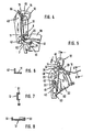
- Fig. 1 eine Schrägansicht auf eine Ausführungsform der Erfindung,
- Fig. 2 eine Teilansicht auf einen Müllbehälter,
- Fig. 3 eine Teilansicht auf einen änderen Müllbehälter,
- Fig. 4 die in Fig.1 dargestellte Ausführungsform in Schrägansicht mit gerade eingehängtem Müllbehälter,
- Fig. 5 eine Fig.4 ähnliche Schrägansicht, jedoch in Kippstellung des Behälters und
- Fig. 6 bis 8 Querschnitte nach den Linien 6-6, 7-7 und 8-8 gemäß den entsprechenden Pfeilen in Fig.5.
- 1 is an oblique view of an embodiment of the invention,
- 2 is a partial view of a waste container,
- 3 is a partial view of a different waste container,
- 4 shows the embodiment shown in FIG. 1 in an oblique view with the garbage container just suspended,
- Fig. 5 is a similar to Figure 4 oblique view, but in the tilted position of the container and
- 6 to 8 cross sections along lines 6-6, 7-7 and 8-8 according to the corresponding arrows in Fig.5.
Eine rechteckige Schüttöffnung 1 an einem nicht weiter dargestellten Müllwagen ist durch einen Rahmen 2 eingefaßt, dessen Oberteil 3 an einen lotrechten Teil 4 anschließt und welcher durch einen unteren Rahmenteil 5 geschlossen wird.A rectangular pouring opening 1 on a garbage truck, not shown, is surrounded by a
Am Rahmen 2 ist eine Kippwelle 6 angebracht, die an beiden Seiten Fangarme 7 aufweist. Da nur eine Öffnungsvorrichtung an einer Seite der Schüttvorrichtung gezeigt ist, ist auch der zweite Fangarm nicht dargestellt. Es wird jedoch davon ausgegangen, daß bei der Schüttvorrichtung an dem dem Rahmenteil 4 gegenüberliegenden Rahmenteil eine spiegelbildgleiche Öffnungsvorrichtung, Wie sie allgemein mit 10 bezeichnet wird, vorgesehen ist.A
Die Öffnungsvorrichtung 10 weist eine gekrümmte Führungsbahn 11 mit einer Führungsschleife 12 auf, deren Krümmungsbereiche weiter unten näher beschrieben sind.The
An der Außenseite des Fangarms 7 ist eine Stange 13 angelenkt, welche über ein Gelenk 14 mit einem Lenker 15 verbunden ist. Die jeweilig freien Enden 16 bzw. 17 der Stange 13 und des Lenkers 15 sind mit Löchern versehen, um ggfs. die nachfolgend näher beschriebene Hebelwirkung beim Verschwenken der Öffnungsvorrichtung 10 zu erhöhen oder zu verringern.A
Die Schüttvorrichtung 1 und damit auch die Öffnungsvorrichtung 10 sind bei der dargestellten Ausführungsform vornehmlich auf die sog. 1,1 m3-Müllbehälter abgestellt; ein Teil eines derartigen Müllgroßbehälters 20 ist in Fig.2 dargestellt. Dieser Müllbehälter hat einen rechteckigen Querschnitt und an einer Seite des Rumpfs 21 ein Scharnier 22, an dem wiederum ein Deckel 23 angelenkt ist. Der Deckel 23 weist an einer Seite 24, und zwar in der Nähe seiner Stirnkante einen Anschlagbolzen 25 auf; auch auf der der Seite 24 gegenüberliegenden Seite des Deckels 23 kann ein entsprechender Anschlagbolzen vorgesehen sein.The pouring device 1 and thus also the
In Figur 3 ist ein ebenfalls 1,1 m3- Müllgroßbehälter 30 dargestellt, an dessen Rumpfteil 31 ein Schwenkdeckel 32 vorgesehen ist, der um an den gegenüberliegenden Seiten des Rumpfteils angeordnete Bolzen 33 verschwenkbar ist.FIG. 3 shows a 1.1 m 3
Um das nachfolgend näher beschriebene selbsttätige Öffnen des Deckels 23 des Behälters 20 zu ermöglichen, wird der Müllbehälter in üblicher Weise in die Fangarme 40 eingesetzt, und zwar dergestalt, daß die Einhängebolzen 26 am Behälter 20 bzw. 36 am Behälter 30 in die Öffnung 41 der spiegelbildgleich angeordneten und mit der Kippwelle 6 verbundenen Fangarme eingesetzt werden.In order to enable the automatic opening of the
Es ist dabei unwesentlich, auf welche Weise der Müllbehälter 20 in der in Fig.4 dargestellten Stellung gehalten wird; es kann üblicherweise ein Kippstuhl vorgesehen sein; es kann jedoch auch eine Einhängung an einer Einhängeleiste vorgenommen werden.It is immaterial how the
Beim Einsetzen des Müllbehälters 20 in die in Fig.4 dargestellte Stellung kommt der Anschlagstift 25 mit der am unteren Ende der Führungsbahn 11 ausgebildeten Führungsschiene in Berührung; diese Führungsschiene ist, wie aus Fig.6 ersichtlich, mit einem L-förmigen Querschnitt versehen, so daß deren Schenkel 42 dafür sorgt, daß der Anschlagbolzen 25 seitlich nicht ausweichen kann.When the
Bei der anfänglichen Hubbewegung des Müllbehälters "rollt" der Anschlagstift auf der Führungsschiene in einem, wie aus Fig.4 näher ersichtlicht ist, leicht konvex gekrümmten Anfangs ab bereich.During the initial lifting movement of the waste container, the stop pin "rolls" on the guide rail in a slightly convexly curved starting area, as can be seen from FIG. 4.
Bei der sich fortsetzenden Hubbewegung und der allmählich einsetzenden Kippbewegung wird der Führungsstift 25 zunächst bis zur Führungsschleife 12 geführt.With the continuing lifting movement and the gradually starting tilting movement, the
Die Führungsschleife 12 weist durchgehend einen U-förmigen Querschnitt auf, wie er z.B. aus Fig.7 oder Fig.8 ersichtlich ist. Die beiden Schenkel 50 und 51 sorgen dafür, daß der Anschlagstift 25 seine Zwangsführung nicht verläßt und daß, bei der Ausführungsform des Müllbehälters nach Fig.2, der Deckel eine in Fig.5 angedeutete Kippstellung einnimmt.Auf diese Weise wird mit Sicherheit vermieden, daß der Deckel bei der Müllentleerung hinderlich ist.The
Bei der Verwendung eines Müllbehälters nach Fig.3 ist das Ausschwenken des Schwenkarms 32 nur über einen Öffnungswinkel von etwas mehr als 90° erforderlich, so daß in diesem Fall die Bewegung des Deckels wesentlich geringer ist als im Falle des Scharnierdeckels 23, wobei es sich versteht, daß die Konfiguration der Führungsbahn mit Führungsschleife eine andere ist, alsWhen using a garbage container according to Figure 3, the pivoting of the
die für einen Behälter nach Fig.2 dargestellte.that shown for a container according to Fig.2.
Die Querschnittserweiterung nach Fig.5 in der Führungsschleife 12 dient dazu, daß beim Kippen des Behälters 20 dessen Einhängebolzen 26 in den Längsschlitzen 45, wie aus Fig.5 ersichtlich, heruntergleiten können, so daß der Behälter 20 in Kippstellung durch die Fangarme 40 auch sicher gehalten wird. Da durch das Verändern der Stellung der Einhängebolzen 26 ein relatives Absinken des Müllbehälters in den Längsschlitzen 45 herbeigeführt wird, muß auch die Zwangsführung für den Anschlagblozen 25 dieser Bewegung folgen können, wofür die Ausbauchung 46 in der Führungsschleife 12 dient.The cross-sectional widening according to FIG. 5 in the
Die Führungsschleife 12 und die damit verbundene Führungsschiene ist so am Rahmen 2 des Müllwagens angebracht, daß eine Verschwenkung der gesamten Öffnungsvorrichtung um ein Gelenk 64 möglich ist. Um diese Verschwenkung der gesamten Führungsbahn zu ermöglichen, ist bei der dargestellten Ausführungsform das Lenkergestänge 13,14,15 vorgesehen. Durch dieses Lenkergestänge wird abhängig von der Kippbewegung des Fangarms 40 eine Verschwenkung der Öffnungsvorrichtung 11,12 um den Gelenkpunkt 64 bewirkt.The
Wie aus Fig.5 ersichtlich ist, führt die Verschwenkung der Öffnungsvorrichtung 11,12 um den Gelenkpunkt 64 dazu, daß in Kippstellung die FührungsschieneAs can be seen from FIG. 5, the pivoting of the
annähernd horizontal liegt. Um zu verhindern, daß etwaig seitlich vorstehende Randteile des Rumpfes des Müllbehälters 20 in die Ebene der Führungsbahn 11 kommen, wird die Verschwenkung der Öffnungsvorrichtung 11,12 schneller vorgenommen als die Kippbewegung des Müllbehälters. Hierfür maßgebend ist einerseits der Abstand des Anlenkpunkts 62 von der Drehachse 63 der Kippwelle 6 und andererseits die wirksame Länge des Lenkers 15 zwischen seinem Anlenkpunkt 64 und dem Gelenkpunkt 14.is approximately horizontal. In order to prevent any laterally protruding edge parts of the trunk of the
Während also der Behälter 20 von der in Fig.4 bis in die in Fig.5 dargestellte Stellung, also um etwa 130° bis 140° verschwenkt wird, wird der Deckel 23 durch die Öffnungsvorrichtung und die Zwangsführung des Anschlagstifts 25 zwangsweise geöffnet, wobei der Öffnungswinkel in diesem Fall etwa 250° groß ist. In der gleichen Zeit wird die Öffnungsvorrichtung, d.h. also die Führungsbahn 11 mit der Führungsschleife 12 und der Führungsschiene um etwa 90° verschwenkt.Thus, while the
Es liegt auf der Hand, daß die beschriebene Öffnungsvorrichtung für annähernd alle Typen von Müllbehältern Verwendung finden kann, und zwar vornehmlich für Müllbehälter, die eine geradlinige Einschlagleiste oder auch eine geradlinige Einhängeleiste aufweisen. Jedoch auch bei runden Mülltonnen ist die Öffnungsvorrichtung anwendbar, wobei allerdings in diesem Fall die Anbringung des Anschlagstifts oder Anschlagvorsprungs an der breitesten Stelle des Deckels erfolgen sollte.It is obvious that the opening device described can be used for almost all types of refuse containers, and in particular for refuse containers which have a rectilinear inlay bar or a rectilinear hanging bar. However, the opening device can also be used with round garbage cans, in which case, however, the stop pin or stop projection should be attached to the widest part of the lid.
Claims (10)
- .1. Device for dumping trash containers at a garbage collecting point, particularly at a garbage cart, having movable receiving arms (7,40) for taking the tresh containers, and having a device for opening the container closure (23,32), comprising a guide path (11) for guiding a stop pin, - bolt or - nose (25,37), being fixed laterally at the container closure, and being engagable with the guide path during the lifting and/or tilting movement, characterized in that the guide path (11) comprises a guide loop (12) and being controlable movable respective to the garbage collecting point in a path plane of the container closure (23,32), depending upon the movement of the receiving arms (7,40).
- 2. Device according claim 1, characterized in that at least the guide loop (12) is formed in the cross section in U-shape.
- 3. Device according claim 2, characterized in that the guide loop (12) comprises at least a cross section widening (46).
- 4. Device according claim 1 or the following, characterized in that there is provided a guide rail being suspended from the guide loop (12) and being curved, at least at its free end.
- 5. Device according claim 1 or the following, characterized in that the guide path (11) turns on a pivot placed at an upper rim of the device.
- 6. Device according claim 1 or the following, characterized in that there is provided a lever system (13,14,15) between a receiving arm (7,40) and the guide loop (12).
- 7. Device according claim 6, characterized in that the lever system comprises a generally perpendicular rod extending from the receiving arm (7,40) to the guide loop (12) and having thereat a pivotly connected link (15) which is connected to the guide loop (12).
- 8. Device according claim 7, characterized in that the rod (13) is placed outside of the receiving arm (40) in the region of the tilt shaft (6) of the device for dumping.
- 9. Device according claim 7 or 8, characterized in that at least the link (15) at its end corresponding to the rod (13) being provided with bores for adjusting its effective length.
- 10. Device according claim 7, characterized in that the rod (13) at its end corresponding to the link (15) comprises several bores.
Priority Applications (1)
| Application Number | Priority Date | Filing Date | Title |
|---|---|---|---|
| AT81108944T ATE18173T1 (en) | 1980-10-31 | 1981-10-26 | DUMP DEVICE FOR WASTE BINS WITH A DEVICE FOR OPENING THE LID. |
Applications Claiming Priority (2)
| Application Number | Priority Date | Filing Date | Title |
|---|---|---|---|
| DE3041105A DE3041105C2 (en) | 1980-10-31 | 1980-10-31 | Dumping device for garbage containers with a device for opening the lid |
| DE3041105 | 1980-10-31 |
Publications (2)
| Publication Number | Publication Date |
|---|---|
| EP0051243A1 EP0051243A1 (en) | 1982-05-12 |
| EP0051243B1 true EP0051243B1 (en) | 1986-02-26 |
Family
ID=6115681
Family Applications (1)
| Application Number | Title | Priority Date | Filing Date |
|---|---|---|---|
| EP81108944A Expired EP0051243B1 (en) | 1980-10-31 | 1981-10-26 | Device for dumping trash containers provided with a device for opening the container closure |
Country Status (8)
| Country | Link |
|---|---|
| US (1) | US4453877A (en) |
| EP (1) | EP0051243B1 (en) |
| AT (1) | ATE18173T1 (en) |
| AU (1) | AU543607B2 (en) |
| DE (1) | DE3041105C2 (en) |
| DK (1) | DK149055C (en) |
| ES (1) | ES506704A0 (en) |
| PT (1) | PT73908B (en) |
Families Citing this family (3)
| Publication number | Priority date | Publication date | Assignee | Title |
|---|---|---|---|---|
| AU608410B2 (en) * | 1988-02-11 | 1991-03-28 | Patents4Us Pty Ltd | Waste collection |
| NZ249049A (en) * | 1992-02-10 | 1996-08-27 | Firebelt Pty Ltd | Side loading refuse collection vehicle for the use with wheeled bins |
| CN113718686A (en) * | 2021-08-23 | 2021-11-30 | 武汉轻工大学 | Automatic dumping device |
Family Cites Families (6)
| Publication number | Priority date | Publication date | Assignee | Title |
|---|---|---|---|---|
| DE478938C (en) * | 1925-09-01 | 1929-07-05 | Niederrheinische Metallwarenfa | Device for the dust-free emptying of garbage cans with hinged lids in collecting containers |
| US2087536A (en) * | 1933-06-30 | 1937-07-20 | Feidert Joseph | Means for coupling garbage pails with the tilting frames of garbage carts |
| GB960724A (en) * | 1961-11-06 | 1964-06-17 | John Gibson & Son Ltd | Improvements in refuse collecting vehicles |
| DE2337278C2 (en) * | 1973-07-23 | 1984-11-08 | Normann 2805 Stuhr Bock | Device for emptying emptying containers into collecting containers |
| DE2627949A1 (en) * | 1976-06-22 | 1978-01-05 | Bock Norman | Discharge unit for empty refuse containers - has guide rails for lifting and tipping container and for opening cover |
| US4239437A (en) * | 1978-10-20 | 1980-12-16 | Zoller-Kipper Gmbh | Heavy duty receptacle unloading device for trucks |
-
1980
- 1980-10-31 DE DE3041105A patent/DE3041105C2/en not_active Expired
-
1981
- 1981-10-26 AT AT81108944T patent/ATE18173T1/en not_active IP Right Cessation
- 1981-10-26 EP EP81108944A patent/EP0051243B1/en not_active Expired
- 1981-10-28 DK DK476181A patent/DK149055C/en not_active IP Right Cessation
- 1981-10-30 PT PT73908A patent/PT73908B/en unknown
- 1981-10-30 US US06/316,663 patent/US4453877A/en not_active Expired - Fee Related
- 1981-10-30 AU AU76975/81A patent/AU543607B2/en not_active Ceased
- 1981-10-30 ES ES506704A patent/ES506704A0/en active Granted
Also Published As
| Publication number | Publication date |
|---|---|
| PT73908A (en) | 1981-11-01 |
| ATE18173T1 (en) | 1986-03-15 |
| DK476181A (en) | 1982-05-01 |
| DE3041105A1 (en) | 1982-05-13 |
| US4453877A (en) | 1984-06-12 |
| DK149055B (en) | 1986-01-06 |
| EP0051243A1 (en) | 1982-05-12 |
| DE3041105C2 (en) | 1983-05-26 |
| ES8207478A1 (en) | 1982-10-01 |
| DK149055C (en) | 1986-06-02 |
| PT73908B (en) | 1983-01-25 |
| ES506704A0 (en) | 1982-10-01 |
| AU543607B2 (en) | 1985-04-26 |
| AU7697581A (en) | 1982-05-06 |
Similar Documents
| Publication | Publication Date | Title |
|---|---|---|
| DE3620610C2 (en) | Gripping device for waste containers | |
| EP0121086B1 (en) | Railway freight wagon | |
| DE2606599C2 (en) | Device for emptying containers, for example garbage cans | |
| EP0051243B1 (en) | Device for dumping trash containers provided with a device for opening the container closure | |
| DE3312557C2 (en) | ||
| DE2733460C2 (en) | ||
| DE2616813C3 (en) | Device on motor vehicles for picking up, setting down and tipping containers | |
| DE2547876C2 (en) | Device for emptying mobile, preferably cart-like, two-wheeled containers into collecting containers | |
| EP0253263B1 (en) | Vehicle with van body and lifting mechanism | |
| DE3304656C2 (en) | ||
| DE2317553C2 (en) | Device for opening the lid when emptying containers, for example garbage cans | |
| DE2920835C2 (en) | Device for emptying garbage containers into a garbage truck | |
| EP0795494B1 (en) | Vehicle for collecting refuse | |
| EP0249726B1 (en) | Cap actuation device for the feed opening of a tank wagon | |
| DE1268539B (en) | Device for emptying garbage cans with a rectangular floor plan and a cylindrically curved lid | |
| DE19746401A1 (en) | Rubbish collection vehicle with lateral lift and tip device | |
| DE4315860C1 (en) | Device to empty discharge system container into refuse collection vehicle - has rocker arm, which may be moved over vehicle intake, and grips journal on hinged bin lid | |
| EP0677458B1 (en) | Lid opener | |
| DE2516789A1 (en) | Rubbish collector vehicle loading mechanism - has dustbin truck guide top sections tilting into emptying position | |
| DE3237879A1 (en) | "Dump body" | |
| DD264408A1 (en) | ARRANGEMENT FOR AUTOMATIC TILTING OF A SWIVELED HOLDER | |
| DE4132087A1 (en) | Lifting and tipping device for refuse containers - has hinged movable lid, to cover individual parts of multi-chamber container during emptying | |
| EP0522113A1 (en) | Railway goods wagon | |
| DE19547831A1 (en) | Refuse collection vehicle with multi-compartment container for different types of waste | |
| CH571438A5 (en) | Skip for empty bottles for recycling - fitted with locked cover with bottle size holes |
Legal Events
| Date | Code | Title | Description |
|---|---|---|---|
| PUAI | Public reference made under article 153(3) epc to a published international application that has entered the european phase |
Free format text: ORIGINAL CODE: 0009012 |
|
| AK | Designated contracting states |
Designated state(s): AT BE CH FR GB IT LU NL SE |
|
| 17P | Request for examination filed |
Effective date: 19820707 |
|
| GRAA | (expected) grant |
Free format text: ORIGINAL CODE: 0009210 |
|
| AK | Designated contracting states |
Designated state(s): AT BE CH FR GB IT LI LU NL SE |
|
| REF | Corresponds to: |
Ref document number: 18173 Country of ref document: AT Date of ref document: 19860315 Kind code of ref document: T |
|
| ITF | It: translation for a ep patent filed |
Owner name: JACOBACCI & PERANI S.P.A. |
|
| ET | Fr: translation filed | ||
| PG25 | Lapsed in a contracting state [announced via postgrant information from national office to epo] |
Ref country code: LU Free format text: LAPSE BECAUSE OF NON-PAYMENT OF DUE FEES Effective date: 19861031 |
|
| PLBE | No opposition filed within time limit |
Free format text: ORIGINAL CODE: 0009261 |
|
| STAA | Information on the status of an ep patent application or granted ep patent |
Free format text: STATUS: NO OPPOSITION FILED WITHIN TIME LIMIT |
|
| 26N | No opposition filed | ||
| PGFP | Annual fee paid to national office [announced via postgrant information from national office to epo] |
Ref country code: LU Payment date: 19901017 Year of fee payment: 10 |
|
| PGFP | Annual fee paid to national office [announced via postgrant information from national office to epo] |
Ref country code: GB Payment date: 19901023 Year of fee payment: 10 |
|
| PGFP | Annual fee paid to national office [announced via postgrant information from national office to epo] |
Ref country code: AT Payment date: 19901024 Year of fee payment: 10 |
|
| PGFP | Annual fee paid to national office [announced via postgrant information from national office to epo] |
Ref country code: BE Payment date: 19901025 Year of fee payment: 10 |
|
| PGFP | Annual fee paid to national office [announced via postgrant information from national office to epo] |
Ref country code: FR Payment date: 19901030 Year of fee payment: 10 |
|
| ITTA | It: last paid annual fee | ||
| PGFP | Annual fee paid to national office [announced via postgrant information from national office to epo] |
Ref country code: SE Payment date: 19901031 Year of fee payment: 10 Ref country code: NL Payment date: 19901031 Year of fee payment: 10 |
|
| PGFP | Annual fee paid to national office [announced via postgrant information from national office to epo] |
Ref country code: CH Payment date: 19901102 Year of fee payment: 10 |
|
| EPTA | Lu: last paid annual fee | ||
| PG25 | Lapsed in a contracting state [announced via postgrant information from national office to epo] |
Ref country code: GB Effective date: 19911026 Ref country code: AT Effective date: 19911026 |
|
| PG25 | Lapsed in a contracting state [announced via postgrant information from national office to epo] |
Ref country code: SE Effective date: 19911027 |
|
| PG25 | Lapsed in a contracting state [announced via postgrant information from national office to epo] |
Ref country code: LI Effective date: 19911031 Ref country code: CH Effective date: 19911031 Ref country code: BE Effective date: 19911031 |
|
| BERE | Be: lapsed |
Owner name: GEBRUDER OTTO K.G. Effective date: 19911031 |
|
| PG25 | Lapsed in a contracting state [announced via postgrant information from national office to epo] |
Ref country code: NL Effective date: 19920501 |
|
| NLV4 | Nl: lapsed or anulled due to non-payment of the annual fee | ||
| GBPC | Gb: european patent ceased through non-payment of renewal fee | ||
| PG25 | Lapsed in a contracting state [announced via postgrant information from national office to epo] |
Ref country code: FR Effective date: 19920630 |
|
| REG | Reference to a national code |
Ref country code: CH Ref legal event code: PL |
|
| REG | Reference to a national code |
Ref country code: FR Ref legal event code: ST |
|
| EUG | Se: european patent has lapsed |
Ref document number: 81108944.0 Effective date: 19920510 |