EP0050397B1 - Billette métallique coulée et procédé et appareil pour sa fabrication - Google Patents
Billette métallique coulée et procédé et appareil pour sa fabrication Download PDFInfo
- Publication number
- EP0050397B1 EP0050397B1 EP81302057A EP81302057A EP0050397B1 EP 0050397 B1 EP0050397 B1 EP 0050397B1 EP 81302057 A EP81302057 A EP 81302057A EP 81302057 A EP81302057 A EP 81302057A EP 0050397 B1 EP0050397 B1 EP 0050397B1
- Authority
- EP
- European Patent Office
- Prior art keywords
- strip
- portions
- crucible
- dissimilar
- casting
- Prior art date
- Legal status (The legal status is an assumption and is not a legal conclusion. Google has not performed a legal analysis and makes no representation as to the accuracy of the status listed.)
- Expired
Links
- 238000000034 method Methods 0.000 title claims description 13
- 238000005266 casting Methods 0.000 claims description 117
- 229910052751 metal Inorganic materials 0.000 claims description 74
- 239000002184 metal Substances 0.000 claims description 74
- 239000000463 material Substances 0.000 claims description 58
- 229910045601 alloy Inorganic materials 0.000 claims description 36
- 239000000956 alloy Substances 0.000 claims description 36
- 239000000203 mixture Substances 0.000 claims description 27
- 230000007704 transition Effects 0.000 claims description 25
- PXHVJJICTQNCMI-UHFFFAOYSA-N Nickel Chemical compound [Ni] PXHVJJICTQNCMI-UHFFFAOYSA-N 0.000 claims description 17
- 230000002093 peripheral effect Effects 0.000 claims description 17
- VYPSYNLAJGMNEJ-UHFFFAOYSA-N Silicium dioxide Chemical compound O=[Si]=O VYPSYNLAJGMNEJ-UHFFFAOYSA-N 0.000 claims description 15
- OKTJSMMVPCPJKN-UHFFFAOYSA-N Carbon Chemical compound [C] OKTJSMMVPCPJKN-UHFFFAOYSA-N 0.000 claims description 11
- XEEYBQQBJWHFJM-UHFFFAOYSA-N Iron Chemical compound [Fe] XEEYBQQBJWHFJM-UHFFFAOYSA-N 0.000 claims description 10
- 238000010791 quenching Methods 0.000 claims description 10
- 229910002804 graphite Inorganic materials 0.000 claims description 9
- 239000010439 graphite Substances 0.000 claims description 9
- MCMNRKCIXSYSNV-UHFFFAOYSA-N Zirconium dioxide Chemical compound O=[Zr]=O MCMNRKCIXSYSNV-UHFFFAOYSA-N 0.000 claims description 8
- 229910052759 nickel Inorganic materials 0.000 claims description 8
- XUIMIQQOPSSXEZ-UHFFFAOYSA-N Silicon Chemical compound [Si] XUIMIQQOPSSXEZ-UHFFFAOYSA-N 0.000 claims description 7
- 239000004927 clay Substances 0.000 claims description 7
- 239000010703 silicon Substances 0.000 claims description 7
- 229910052710 silicon Inorganic materials 0.000 claims description 7
- CPLXHLVBOLITMK-UHFFFAOYSA-N Magnesium oxide Chemical compound [Mg]=O CPLXHLVBOLITMK-UHFFFAOYSA-N 0.000 claims description 6
- PNEYBMLMFCGWSK-UHFFFAOYSA-N aluminium oxide Inorganic materials [O-2].[O-2].[O-2].[Al+3].[Al+3] PNEYBMLMFCGWSK-UHFFFAOYSA-N 0.000 claims description 6
- 230000007797 corrosion Effects 0.000 claims description 6
- 238000005260 corrosion Methods 0.000 claims description 6
- 238000000151 deposition Methods 0.000 claims description 6
- 230000000171 quenching effect Effects 0.000 claims description 6
- 239000000377 silicon dioxide Substances 0.000 claims description 6
- VYZAMTAEIAYCRO-UHFFFAOYSA-N Chromium Chemical compound [Cr] VYZAMTAEIAYCRO-UHFFFAOYSA-N 0.000 claims description 5
- 239000000470 constituent Substances 0.000 claims description 5
- 239000005995 Aluminium silicate Substances 0.000 claims description 4
- 229910052580 B4C Inorganic materials 0.000 claims description 4
- 229910052582 BN Inorganic materials 0.000 claims description 4
- PZNSFCLAULLKQX-UHFFFAOYSA-N Boron nitride Chemical compound N#B PZNSFCLAULLKQX-UHFFFAOYSA-N 0.000 claims description 4
- 229910052581 Si3N4 Inorganic materials 0.000 claims description 4
- 235000012211 aluminium silicate Nutrition 0.000 claims description 4
- INAHAJYZKVIDIZ-UHFFFAOYSA-N boron carbide Chemical compound B12B3B4C32B41 INAHAJYZKVIDIZ-UHFFFAOYSA-N 0.000 claims description 4
- NLYAJNPCOHFWQQ-UHFFFAOYSA-N kaolin Chemical compound O.O.O=[Al]O[Si](=O)O[Si](=O)O[Al]=O NLYAJNPCOHFWQQ-UHFFFAOYSA-N 0.000 claims description 4
- 239000010453 quartz Substances 0.000 claims description 4
- 229910010271 silicon carbide Inorganic materials 0.000 claims description 4
- HBMJWWWQQXIZIP-UHFFFAOYSA-N silicon carbide Chemical compound [Si+]#[C-] HBMJWWWQQXIZIP-UHFFFAOYSA-N 0.000 claims description 4
- HQVNEWCFYHHQES-UHFFFAOYSA-N silicon nitride Chemical compound N12[Si]34N5[Si]62N3[Si]51N64 HQVNEWCFYHHQES-UHFFFAOYSA-N 0.000 claims description 4
- BPQQTUXANYXVAA-UHFFFAOYSA-N Orthosilicate Chemical compound [O-][Si]([O-])([O-])[O-] BPQQTUXANYXVAA-UHFFFAOYSA-N 0.000 claims description 3
- 229910052782 aluminium Inorganic materials 0.000 claims description 3
- XAGFODPZIPBFFR-UHFFFAOYSA-N aluminium Chemical compound [Al] XAGFODPZIPBFFR-UHFFFAOYSA-N 0.000 claims description 3
- 229910052570 clay Inorganic materials 0.000 claims description 3
- 239000010941 cobalt Substances 0.000 claims description 3
- 229910017052 cobalt Inorganic materials 0.000 claims description 3
- GUTLYIVDDKVIGB-UHFFFAOYSA-N cobalt atom Chemical compound [Co] GUTLYIVDDKVIGB-UHFFFAOYSA-N 0.000 claims description 3
- 239000001095 magnesium carbonate Substances 0.000 claims description 3
- ZLNQQNXFFQJAID-UHFFFAOYSA-L magnesium carbonate Chemical compound [Mg+2].[O-]C([O-])=O ZLNQQNXFFQJAID-UHFFFAOYSA-L 0.000 claims description 3
- 229910000021 magnesium carbonate Inorganic materials 0.000 claims description 3
- 235000014380 magnesium carbonate Nutrition 0.000 claims description 3
- 239000000395 magnesium oxide Substances 0.000 claims description 3
- 229910002076 stabilized zirconia Inorganic materials 0.000 claims description 3
- ZOXJGFHDIHLPTG-UHFFFAOYSA-N Boron Chemical compound [B] ZOXJGFHDIHLPTG-UHFFFAOYSA-N 0.000 claims description 2
- 229910052790 beryllium Inorganic materials 0.000 claims description 2
- ATBAMAFKBVZNFJ-UHFFFAOYSA-N beryllium atom Chemical compound [Be] ATBAMAFKBVZNFJ-UHFFFAOYSA-N 0.000 claims description 2
- 229910052796 boron Inorganic materials 0.000 claims description 2
- 229910052799 carbon Inorganic materials 0.000 claims description 2
- 229910052804 chromium Inorganic materials 0.000 claims description 2
- 239000011651 chromium Substances 0.000 claims description 2
- BHEPBYXIRTUNPN-UHFFFAOYSA-N hydridophosphorus(.) (triplet) Chemical compound [PH] BHEPBYXIRTUNPN-UHFFFAOYSA-N 0.000 claims description 2
- 239000012535 impurity Substances 0.000 claims description 2
- 229910052742 iron Inorganic materials 0.000 claims description 2
- 239000010935 stainless steel Substances 0.000 claims description 2
- 229910001220 stainless steel Inorganic materials 0.000 claims description 2
- 229910052720 vanadium Inorganic materials 0.000 claims description 2
- LEONUFNNVUYDNQ-UHFFFAOYSA-N vanadium atom Chemical compound [V] LEONUFNNVUYDNQ-UHFFFAOYSA-N 0.000 claims description 2
- 239000004411 aluminium Substances 0.000 claims 1
- 230000002411 adverse Effects 0.000 description 10
- 238000004519 manufacturing process Methods 0.000 description 9
- 239000002131 composite material Substances 0.000 description 7
- RYGMFSIKBFXOCR-UHFFFAOYSA-N Copper Chemical compound [Cu] RYGMFSIKBFXOCR-UHFFFAOYSA-N 0.000 description 6
- 239000010949 copper Substances 0.000 description 6
- 239000002178 crystalline material Substances 0.000 description 6
- 238000005520 cutting process Methods 0.000 description 6
- 229910000808 amorphous metal alloy Inorganic materials 0.000 description 5
- 229910052802 copper Inorganic materials 0.000 description 5
- 238000010438 heat treatment Methods 0.000 description 5
- XKRFYHLGVUSROY-UHFFFAOYSA-N Argon Chemical compound [Ar] XKRFYHLGVUSROY-UHFFFAOYSA-N 0.000 description 4
- 238000001816 cooling Methods 0.000 description 4
- 239000007769 metal material Substances 0.000 description 4
- XLYOFNOQVPJJNP-UHFFFAOYSA-N water Substances O XLYOFNOQVPJJNP-UHFFFAOYSA-N 0.000 description 4
- 229910000881 Cu alloy Inorganic materials 0.000 description 3
- 229910000905 alloy phase Inorganic materials 0.000 description 3
- 238000002425 crystallisation Methods 0.000 description 3
- 230000008025 crystallization Effects 0.000 description 3
- 230000006698 induction Effects 0.000 description 3
- 238000012423 maintenance Methods 0.000 description 3
- 229910001092 metal group alloy Inorganic materials 0.000 description 3
- 239000012768 molten material Substances 0.000 description 3
- 230000002459 sustained effect Effects 0.000 description 3
- 238000003466 welding Methods 0.000 description 3
- ZOKXTWBITQBERF-UHFFFAOYSA-N Molybdenum Chemical compound [Mo] ZOKXTWBITQBERF-UHFFFAOYSA-N 0.000 description 2
- 238000002441 X-ray diffraction Methods 0.000 description 2
- 238000005275 alloying Methods 0.000 description 2
- 229910052786 argon Inorganic materials 0.000 description 2
- 230000009286 beneficial effect Effects 0.000 description 2
- 238000005219 brazing Methods 0.000 description 2
- 238000009749 continuous casting Methods 0.000 description 2
- 238000011161 development Methods 0.000 description 2
- 230000018109 developmental process Effects 0.000 description 2
- 239000006185 dispersion Substances 0.000 description 2
- 230000001747 exhibiting effect Effects 0.000 description 2
- 239000011810 insulating material Substances 0.000 description 2
- 238000005304 joining Methods 0.000 description 2
- 150000002739 metals Chemical class 0.000 description 2
- 229910052750 molybdenum Inorganic materials 0.000 description 2
- 239000011733 molybdenum Substances 0.000 description 2
- 238000005476 soldering Methods 0.000 description 2
- 229910000838 Al alloy Inorganic materials 0.000 description 1
- 229910001369 Brass Inorganic materials 0.000 description 1
- 229910000831 Steel Inorganic materials 0.000 description 1
- 230000015572 biosynthetic process Effects 0.000 description 1
- 239000010951 brass Substances 0.000 description 1
- 239000004568 cement Substances 0.000 description 1
- 238000005056 compaction Methods 0.000 description 1
- 238000010924 continuous production Methods 0.000 description 1
- 230000008602 contraction Effects 0.000 description 1
- 239000002826 coolant Substances 0.000 description 1
- 230000000694 effects Effects 0.000 description 1
- 239000012530 fluid Substances 0.000 description 1
- 230000008014 freezing Effects 0.000 description 1
- 238000007710 freezing Methods 0.000 description 1
- 239000004615 ingredient Substances 0.000 description 1
- 238000009413 insulation Methods 0.000 description 1
- 230000000670 limiting effect Effects 0.000 description 1
- 239000007788 liquid Substances 0.000 description 1
- 238000002844 melting Methods 0.000 description 1
- 230000008018 melting Effects 0.000 description 1
- 230000036961 partial effect Effects 0.000 description 1
- 230000035699 permeability Effects 0.000 description 1
- 238000001556 precipitation Methods 0.000 description 1
- 238000012545 processing Methods 0.000 description 1
- 230000002035 prolonged effect Effects 0.000 description 1
- 230000001681 protective effect Effects 0.000 description 1
- 238000005057 refrigeration Methods 0.000 description 1
- 230000000717 retained effect Effects 0.000 description 1
- 230000002441 reversible effect Effects 0.000 description 1
- 230000003068 static effect Effects 0.000 description 1
- 239000010959 steel Substances 0.000 description 1
- 238000003860 storage Methods 0.000 description 1
- 239000000126 substance Substances 0.000 description 1
- 238000012360 testing method Methods 0.000 description 1
Images

Classifications
-
- B—PERFORMING OPERATIONS; TRANSPORTING
- B22—CASTING; POWDER METALLURGY
- B22D—CASTING OF METALS; CASTING OF OTHER SUBSTANCES BY THE SAME PROCESSES OR DEVICES
- B22D11/00—Continuous casting of metals, i.e. casting in indefinite lengths
-
- B—PERFORMING OPERATIONS; TRANSPORTING
- B22—CASTING; POWDER METALLURGY
- B22D—CASTING OF METALS; CASTING OF OTHER SUBSTANCES BY THE SAME PROCESSES OR DEVICES
- B22D11/00—Continuous casting of metals, i.e. casting in indefinite lengths
- B22D11/007—Continuous casting of metals, i.e. casting in indefinite lengths of composite ingots, i.e. two or more molten metals of different compositions being used to integrally cast the ingots
-
- B—PERFORMING OPERATIONS; TRANSPORTING
- B22—CASTING; POWDER METALLURGY
- B22D—CASTING OF METALS; CASTING OF OTHER SUBSTANCES BY THE SAME PROCESSES OR DEVICES
- B22D11/00—Continuous casting of metals, i.e. casting in indefinite lengths
- B22D11/06—Continuous casting of metals, i.e. casting in indefinite lengths into moulds with travelling walls, e.g. with rolls, plates, belts, caterpillars
- B22D11/0611—Continuous casting of metals, i.e. casting in indefinite lengths into moulds with travelling walls, e.g. with rolls, plates, belts, caterpillars formed by a single casting wheel, e.g. for casting amorphous metal strips or wires
-
- B—PERFORMING OPERATIONS; TRANSPORTING
- B22—CASTING; POWDER METALLURGY
- B22D—CASTING OF METALS; CASTING OF OTHER SUBSTANCES BY THE SAME PROCESSES OR DEVICES
- B22D19/00—Casting in, on, or around objects which form part of the product
- B22D19/14—Casting in, on, or around objects which form part of the product the objects being filamentary or particulate in form
Definitions
- the present invention relates to a rapidly quenched cast metallic strip and to a method and apparatus for producing such strip.
- This invention is directed to metallic strip materials, whether amorphous, crystalline or combinations thereof, having dissimilar portions.
- this invention relates to metal alloys in strip form, at least a portion of which are amorphous.
- amorphous is intended to refer to a composition in which at least 50% is amorphous, which is typically measured by X-ray defraction.
- a preferred embodiment of the present invention pertains to strip material in which at least one dissimilar portion is amorphous.
- Amorphous metal alloys are those produced by a process in which crystallization is avoided, typically by extremely rapidly quenching the metal from the liquid state. Such cooling rate is usually of the order of at least 104°C per second. Because of their atomic arrangement and composition, some amorphous alloys can possess enhanced properties, including higher strength and increased resistance to chemical attack when compared to conventional crystalline alloys. Therefore, such amorphous alloys may be ideally suited for uses including but not limited to razor blade edge materials due to their properties of strength, hardness, ductility and corrosion resistance. Certain amorphous materials are also known to possess enhanced magnetic and electrical properties and the strip of the present invention may be desirable for electrical end uses.
- the present invention applies equally to rapidly cast crystalline metallic materials which have a multitude of uses.
- the present invention further comprehends combinations of dissimilar crystalline metallic materials, dissimilar amorphous metallic materials and combinations thereof where it is desirable to utilize such dissimilar materials to decrease the overall cost of the composite, or multiplex strip, or to localize desired properties, gauge, etc. of dissimilar materials in a composite strip.
- the present invention may be utilized to produce delicate material by simultaneously providing edge portions of a more rugged material which would facilitate the handling of the delicate material. After production, the handling portions could easily be trimmed from the strip.
- this invention could be utilized to join alloys which exhibit different thermal electric properties, suitable for use in the production of thermocouples or multiple thermocouples.
- the present invention may be employed to cast strip having varying gauges across the width thereof to intentionally vary the mechanical strength, electrical properties, etc. across the width of the strip. Further, this invention can be used to produce strip having alloys of various expansion characteristics across the width thereof. Thus, by heating such strip an intentional curvilinear strip configuration may be obtained. It should be understood that a variety of applications can be made of the strip of this invention, and that the above examples are merely illustrative and should not be interpreted as limiting the scope of this invention in any manner.
- a new and improved multiplex strip material is desired in which dissimilar portions are joined in a fashion which does not adversely affect either the overall quality of such individual strip components or the integrity of each of such strips.
- a new and improved method and apparatus for producing such strip components and multiplex combinations is desired.
- German Offenlegungsschrift No., 2,856,795 discloses a number of embodiments of metallic strip manufacture by delivering to a rotating chill drum from multi-orifice nozzles a plurality of melt streams which run or fuse together. It discloses that a double-layer strip of two dissimilar metals can be made by depositing a first metal stream on to the chill drum and thereafter depositing a second metal stream to form a second layer over, and co-extensive with, the cast first stream.
- the present invention provides a rapidly quenched, cast metallic strip comprising a plurality of dissimilar rapidly quenched, cast metallic portions, each portion metallurgically alloy-bonded during casting to an adjacent portion along the longitudinal extent of said strip, wherein said plurality of portions are dissimilar portions of at least two different compositions, and each portion is metallurgically alloy-bonded during casting to a laterally adjacent dissimilar portion along the adjacent edges of said dissimilar portions.
- the present invention also provides a method of casting metallic strip having a plurality of dissimilar portions metallurgically alloy-bonded along the longitudinal extent of said strip, comprising delivering a plurality of streams of molten metal from a plurality of nozzles onto a rapid quenching casting surface moving at a rate of from 61 to 3048 metres (200 to 10,000 linear surface feet) per minute past said nozzles characterised by depositing a first stream of a first molten metal onto said casting surface from a nozzle of a first crucible and depositing laterally of the first at least one additional stream of a second, different molten metal from a nozzle of a second crucible onto said casting surface such that a peripheral edge portion of said at least one additional stream contacts a peripheral edge portion of adjacent different metal to create a metallurgical alloy-bond therebetween during casting.
- the present invention further provides apparatus for casting metallic strip having a plurality of dissimilar portions metallurgically alloy-bonded along the longitudinal extent of said strip, comprising crucible means for receiving and holding molten metal and having a plurality of nozzles through which a plurality of streams of molten metal can be delivered from said means to a rapid quenching casting surface located within 3.048 mm (0.120 inch) of the nozzles and movable past the nozzles at a speed of from 61 to 3048 metres (200 to 10,000 linear surface feet) per minute, wherein said crucible means comprises a first crucible having an internal cavity for receiving and holding molten metal and a nozzle through which a first stream of molten metal can be delivered from its cavity and deposited onto the casting surface, and at least one additional crucible having an internal cavity for receiving and holding molten metal and a nozzle through which at least one additional stream of a second, different molten metal can be delivered from its cavity and deposited onto the casting surface, said at least one additional
- Another advantage of the present invention is that it enables a strip of rapidly cast material to be provided having at least two 'dissimilar portions metallurgically alloy-bonded along the length of the strip thereby forming a multiplex strip,. or composite strip, exhibiting different properties, structure or quality in each portion of the strip.
- Another advantage of the present invention is the provision of a method and an apparatus for rapidly casting a strip comprised of dissimilar portions metallurgically alloy-bonded to one another along the length of the strip during casting operations without adversely affecting the quality or the properties of the strip material.
- a further advantage of the present invention is that where strength, corrosion resistance and other qualities are required only at an edge or at the edges of the strip material, the expensive alloying ingredients, such as cobalt and molybdenum only have to be used at such edge portions of a multiplex strip material, thus reducing the cost of the strip.
- Another advantage of this invention is that it enables a strip of metallurgically alloy-bonded amorphous and crystalline metallic portions to be provided without causing the amorphous portion to crystallize during the bonding thereof
- the invention also enables a metallic strip to be provided of components joined at a transition zone wherein an alloy formed at the transition zone has enhanced properties over those of the joined portions.
- Figures 1 and 2 illustrate a preferred apparatus of the present invention.
- this apparatus includes a first crucible 10 and a second crucible 11 each having an internal cavity designed to receive and hold metal.
- the first crucible 10 also includes an orifice or nozzle 10a through which a first stream of molten metal can be delivered from the cavity of the crucible 10 to a casting surface 18 whilst the second crucible 11 likewise includes an orifice or nozzle 11 a through which a second stream of molten metal can be delivered from the cavity of the crucible 11 to the casting surface 18.
- the continuous strip material 30 (Figs 3, 4 and 6) is cast on a relatively smooth outer peripheral surface 18 of a circular drum or wheel 13.
- the strip of the present invention could be cast onto a moving belt as shown in Figure 6, onto the interior surface of the drum, between a pair of facing rollers, into a quench fluid, or the like.
- the casting element 13 comprises a water cooled, precipitation hardened copper alloy wheel containing about 90% copper.
- Copper and copper alloys are chosen for their high thermal conductivity and wear resistance.
- steel brass, aluminum, aluminum alloys or other materials may be utilized alone or in combination or multipiece wheels having sleeves of molybdenum or other material may also be employed.
- cooling may be accomplished with the use of a medium other than water. Water is chosen for the preferred embodiment for its low cost and its ready availability.
- the outer peripheral surface 18 of the casting wheel 13 must be able to absorb the heat generated by contact with molten metal at the initial casting point, and such heat must diffuse substantially into the copper wheel during each rotation of the wheel. Removal of the diffused heat may be accomplished, for example, by delivering a sufficient quantity of water through internal passageways located near the periphery of the casting wheel 13. Alternatively, the cooling medium may be delivered to the underside of the casting surface. Understandably, refrigeration techniques and the like may be employed to adjust and optimize cooling rates, for example, to effect wheel expansion or contraction during strip casting.
- the casting surface 18 should generally be smooth and symmetrical to maximize uniformity in strip casting.
- the distance between the outer peripheral casting surface 18 and the surfaces defining the orifice of the nozzle 10a or 1 a which is feeding the molten material onto the casting surface 18 should not substantially deviate from a desired or set distance. This distance shall hereinafter be called the standoff distance or gap. It is understandable that the gap at each nozzle should normally be substantially maintained constant throughout the casting operation when it is the intention of the operator to cast uniform gauge strip portions from that nozzle. If, however, controlled variations of thickness are desired either in the complete composite or in certain component strips of the composite, then a programmed standoff distance both for the whole nozzle component array and/or for each contributing nozzle may be employed.
- the casting element is a drum or a wheel
- the element should be carefully constructed so as not to be out-of-round during operation to ensure uniformity in strip casting.
- a drum or wheel which is out-of-round by about 0.508 mm (0.020 inch), or more may have a magnitude of dimensional instability which, unless corrected or compensated during operation, may be unacceptable for certain strip casting operations.
- acceptable dimensional symmetry may be accomplished by fabricating a wheel or drum from a single, integral slab of cold rolled or forged copper.
- alternative materials may be employed.
- the molten materials to be cast in the apparatus described herein are preferably retained in crucibles or tundishes each of which is provided with a corresponding nozzle.
- the nozzle is typically, though not necessarily, located at a lower portion of the crucible as shown in the drawings.
- the nozzle may be an integral part of the crucible, or may constitute a separate material affixed into the crucible.
- Each crucible is constructed for receiving and holding molten metal therein. It will be appre-. ciated that appropriate materials must be utilized for the crucible to withstand the molten metal conditions, and where the crucible is not a monolithic structure, the joints and seams between separate pieces of the crucible must be assembled to prevent molten metal leakage during sustained operation.
- molten metal holding portion of the crucible 10 which is formed between the inside surfaces, may take a variety of forms or shapes.
- an upper portion of the crucible 10 has a significantly larger cross-sectional volume than that of the nozzle area of the crucible 10 in order that the molten metal head height, above the nozzle 10a, is substantially unaffected by minor variations in molten metal in the crucible 10.
- Such structure contributes to the maintenance of a substantially constant metallostatic head pressure at the nozzle, even with minor variations in metal volume that may occur in the crucible 10 in sustained or continuous casting operations. It should be appreciated that casting may also be effected under externally applied pressure using equipment which could be directly controlled.
- the inside surfaces of the crucible 10 converge toward one'another in the direction of the nozzle 10a, and that such inside surfaces be radiused, rounded or generally curvilinear at locations of turns or bends in the crucible 10 to minimize metal turbulence therein during a casting operation.
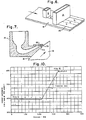
- molten metal holding area, formed between the inside surfaces of the crucible 10 shown in Figure 7 should be enclosed, such as with sidewalls. It is noted that the width of the crucible nozzles of the present invention should not be limited. It has been found that a crucible 10 and nozzle 1 Oa of the present invention may be constructed by first cutting or carving refractory boards, such as insulating boards made from fiberized kaolin, into the desired shape, such as that shown in Figure 7. Any number of these boards may be stacked upon one another to obtain the desired crucible 10 and nozzle 10a width.
- refractory boards such as insulating boards made from fiberized kaolin
- the inside surfaces may be sanded or otherwise finished to provide generally smooth inside surfaces across the width of the stacked elements forming the crucible 10. It should also be understood that single piece materials may be used to construct a monolithic crucible in which case stacking would not be necessary. After the carved boards are stacked, the stack may be disposed between uncarved boards, which may serve as the sidewalls for the crucible 10.
- the crucible may be assembled with refractory cements, or the like, or may be constructed of a monolithic structure which does not require assembly.
- a nozzle is located in each crucible, preferably in a lower portion thereof.
- the nozzle comprises an orifice passage defined between inside surfaces of the crucible.
- the nozzle 10a is formed between a crucible surface and an inside surface of an insert 50. A portion of the inside surface of the insert 50, is preferably disposed against a portion of a ridge formed by an outside surface of the crucible 10.
- the insert 50 described in a preferred crucible, may be easily replaced, although it is preferred that the insert 50 and the crucible be reused, either together or separately. It should also be noted that damage to an insert 50 shall not render the entire crucible unserviceable. In the event of such insert damage, the insert 50 is merely replaced and the process may continue.
- the insert 50 is provided with a front edge surface 70.
- the front edge surface 70 faces the casting surface 18 and is disposed to within less than 3.048 mm (0.120 inch) of the casting surface 18.
- the front edge surface 70 is disposed to within 2.032 mm (0.080 inch) and in a more preferred embodiment, to within 0.508 'mm (0.020 inch) of the casting surface 18.
- the front edge surface 70 be in substantially complete parallelism with the casting surface 18. Such complete parallelism may be accomplished by placing a sheet of sandpaper, or the like, against the casting surface 18 with the grit side of the sandpaper facing the insert 50.
- the front edge surface 70 is ground by the grit side of the sandpaper into substantially complete parallelism with the casting surface 18.
- Such substantially complete parallelism may be achieved even when round or other curvilinear casting surfaces are employed.
- 400 to 600 grit sandpaper has been found to be adequate.
- Other surfaces of the crucible may be brought into substantially complete parallelism with the casting surfaces 18 by this same procedure.
- the standoff distance, or gap, between the front edge surface 70 and the casting surface 18 is maintained throughout the length thereof. It has been found that the gap between the front edge surface 70 and the casting surface 18 should be maintained at less than 3.048 mm (0.120 inch) in order to successfully cast strip material. Preferably, this gap is maintained at less than 2.032 mm (0.080 inch) and for casting certain alloys into thin gauge strip, gaps less than 0.508 mm (0.020 inch) are preferred.
- the corner of the insert 50 may come to a point at the front edge 70 at a 90° junction of the front edge of the insert 50, as opposed to a defined surface length as discussed above.
- the bottom surface of the nozzle 10a is that such surface be disposed as close as possible to the casting surface 18, without causing any interference for the movable casting surface therebelow. Accordingly, such surface of the nozzle may just clear the casting surface 18, i.e., be perhaps within about 0.0508 mm (.002 inch) thereof. Such spacing must not be large enough to allow significant molten metal backflow between the bottom surface of the nozzle 10 and the casting surface 18 during casting. It should be understood that provision may have to be made for edge portions of strip material which may have to pass under a portion of another downstream crucible.
- the crucibles 10 and/or 11 are preferably constructed of a material having superior insulation ability. If the insulating ability is not sufficient to retain the molten material at a relatively constant temperature, auxiliary heaters such as induction coils 12 may have to be provided in and/or around the crucibles 10 and/or 11, or resistance elements such as wires may be provided.
- a convenient material for the crucibles is an insulating board made from fiberized kaolin, a naturally occurring, high purity, alumina-silica fire clay. Such insulating material is available under the trade mark Kaowool HS board.
- various other materials may have to be employed for constructing the crucible or the nozzle of the crucible including silica, alumina, graphite, alumina graphite, clay graphite, fire clay, quartz, boron nitride, silicon nitride, boron carbide, silicon carbide, zirconia, stabilized zirconia silicate, magnesia, chrome magnesite and various combinations or mixtures of such materials.
- the insert 50 forming part of the nozzle of the crucible is preferably constructed of boron nitride, silicon nitride, silicon carbide, boron carbide, zirconia or quartz.
- the orifice passage of the nozzle 1 Oa or 11 a remain open and its configuration remain substantially stable throughout a strip casting operation. It is understandable that the nozzles should not erode or clog, significantly, during a multiplex strip casting sequence or certain objectives such as maintaining uniformity in the casting operation and of minimizing metal flow turbulence in the crucibles may be defeated. Along these lines, it appears that certain insulating materials may not be able to maintain their dimensional stability over long casting periods. To obviate this problem the nozzle 10a or 11 a, especially that portion defined by an insert 50, may be constructed of a material which is better able to maintain dimensional stability and integrity during exposure to high molten metal temperatures for prolonged time periods. Hence the preference for the materials mentioned above.
- the drive system and housing for the drum, wheel or other casting surface 16 of the present invention should be rigidly constructed to permit drum rotation without structural instability which would cause the drum to slip or vibrate. In particular, care should be taken to avoid resonant frequencies at the operating speeds for the drum.
- the casting surface 18 should be capable of moving at a surface speed of from 61 metres (200 linear surface feet) per minute to more than 3048 metres (10,000 linear surface feet) per minute. When utilizing a drum having a circumference of about 2.4 metres (8 feet), this rate calculates to a drum speed from about 25 rpm to about 1250 rpm.
- a three horsepower variable speed reversible, dynamically braked motor provides an adequate drive system for an integral copper casting drum 50 to 254 mm (2 to 10 inches) thick and about 2.4 metres (8 feet) in circumference. Power requirements may have to be modified depending upon the type and size of casting surface 18 employed. It should be appreciated that the casting surface 18 can be moved in a direction opposite to that illustrated in the drawing, and that the crucible may be disposed at any location about a circular casting wheel.
- the casting surface 18 on the wheel or drum of the apparatus of the present invention is smooth. It has been found that in certain applications, such as for producing amorphous strip portions, finishing the peripheral surface 18 of a casting wheel 13 with 400-grit sandpaper and preferably with 600-grit sandpaper may yield improved product uniformity.
- molten metal is delivered to a first, heated crucible 10 and into a second crucible 11, although such metal delivery may be sequential rather than simultaneous.
- a heater such as induction coils or resistance wire 12 may be provided in and/or about the crucibles 10 and 11 to obtain or to maintain relatively constant molten metal temperatures as may be desired.
- metal may be poured directly into preheated crucibles.
- Such metal preheat temperature and the heating of the crucibles by auxiliary devices should prevent freezing or clogging of the nozzle during the initial casting operation, and the temperature of the flowing metal should thereafter keep each crucible at sufficient temperature to ensure uninterrupted molten metal flow through each nozzle.
- the nozzle should be externally heated throughout the casting operation.
- the metal which is fed to the crucibles may be superheated to allow a certain degree of temperature loss without adversely affecting metal flow.
- a metallostatic head height in the crucibles should be maintained at a relatively constant level throughout the casting operation to ensure that a relatively constant static head pressure is maintained at the nozzles. This may be accomplished by initially pouring the molten metal into each crucible to the desired height and thereafter controlling the rate at which additional molten metal is poured into that crucible to maintain the metallostatic head. It is understandable that the rate at which additional molten metal is fed to the crucible should be in substantial conformity with the rate at which metal flows from the nozzle onto the casting surface 18 in forming the multiplex strip material of the present invention.
- a rapidly quenched metallic strip 30 is cast onto a casting surface 18.
- strip material 30 comprises a plurality of dissimilar portions, such as portions a, b, c and d in Figure 5 or portions a" b, and a 2 in Figure 6.
- Each individual portion of the strip 30 is metallurgically alloy-bonded to the edges of adjacent portions along the longitudinal extent of the strip. Further, such metallurgical alloy-bonding occurs as an integral part of the strip casting operation.
- Strip 30 having a plurality of dissimilar portions is called “multiplex strip” or “composite strip” in this application.
- the multiplex strip 30 of the present invention is intended to comprehend a strip having at least two dissimilar metallic materials metallurgically alloy-bonded together along the longitudinal extent of the strip. This metallurgical alloy-bdnd occurs during the casting operation which forms the strip.
- the "at least two different materials” refers to different metallic compositions.
- such expression should also comprehend a multiplex strip which additionally has other properties which are different, including, but not limited to, electrical resistivity, permeability, conductivity, core loss characteristics, yield strength, hardness, atomic arrangement, gauge, corrosion resistance, thermal expansion, colour and the like.
- one portion of a multiplex strip of the present invention may have expansion characteristics different from that of a bonded, adjacent portion.
- an intentional curvilinear strip material may >be obtained.
- the present invention may be employed to produce multiplex strip having amorphous strip portions metallurgically alloy-bonded to crystalline strip portions.
- a strip of amorphous material is joined by conventional means, involving heating, such as welding, to a strip of crystalline material the amorphous strip becomes very brittle since the temperature to which it is exposed exceeds the crystallization temperature.
- the quench rate may be so rapid that crystallization of the amorphous strip portion is substantially avoided, except possibly at the transition zone.
- the rapid quenching of a strip casting operation may also be beneficial in the production of certain crystalline strip materials.
- Fast quenched crystalline alloys in general, typically develp a highly desirable microstructure which is finer than conventionally produced crystalline materials.
- rapidly cast crystalline materials may contain desirable alloy phases not found in conventional crystalline materials, and, conversely, rapid casting may avoid or inhibit the formation of adverse alloy phases. Additionally, rapid casting can. produce new alloy phases in crystalline materials which although they are metastable, typically exhibit improved properties.
- the present invention pertains to the manufacturing of multiplex strip 30 having an amorphous alloy portion which is formed with an adjacent metal or metal alloy portion, which may or may not be amorphous, the latter portion being integral with the first mentioned amorphous alloy portion.
- the multiple strip portions may be cast simultaneously adjacent one another onto the casting surface 18, as shown in the embodiment illustrated in Figures 1 and 2.
- the multiple nozzles 1 Oa and 11 a each deposit a stream of molten metal 20 and 22, respectively, onto approximately the same transverse line across the casting surface 18, adjacent to one another.
- the molten streams of metal converge to join one another and an actual alloying of the two converging streams actually occurs at the interface, also called the transition zone.
- the quench rate is so rapid in the casting of metallic strip material, that the merging streams do not experience sufficient residence time to significantly adversely affect the integrity of either metallic stream outside of the transition zone. Therefore, the composition gauge, hardness, strength, ductility, corrosion resistance and other properties of one portion of the strip are not adversely affected by the contact between adjacent portions even in their molten state.
- the multiple strip portions may be cast successively onto the casting surface 18 as shown in the embodiments illustrated in Figures 3 and 4.
- a stream of molten metal is fed from one crucible 10 onto the casting surface 18.
- a second crucible 11 is located downstream of the first crucible 10 with respect to the casting direction illustrated by the arrow in Figure 3.
- the second crucible 11 has a nozzle 11 a which must be disposed such that a peripheral edge portion of the second stream of metal contacts a peripheral edge portion of the first metal to create a metallurgical alloy-bond therebetween during casting. It will be appre- . ciated that the first stram may be molten, partially solidified or even totally solidified when the second stream contacts the peripheral edge. What is required by the casting operation is that a metallurgical alloy-bond be created therebetween as the multiplex strip is formed.
- Figure 5 illustrates a multiplex strip composed of four portions a, b, c and d cast from four separate crucibles A, B, C, D.
- Figure 6 illustrates a triplex strip which may be cast by disposing two streams of metal from two separate nozzles in a common crucible A adjacent both edge portions of a single strip portion, b, from tundish B to produce a multiplex strip having portions a,, b, and a 2 metallurgically alloy-bonded during casting.
- the two nozzles of crucible A are preferably separated by a bridge of approximately the same width as the central strip portion b.
- transition zone In forming the metallurgical alloy-bond between adjacent dissimilar portions, such dissimilar strip portions are fused to one another.
- the joint between adjacent dissimilar portions which is called the "transition zone" throughout this application, normally extends through the strip from its upper face to its lower face in a direction substantially parallel to the longitudinal axis of a strip.
- One preferred embodiment of this invention may be directed to the production of razor blade stock.
- the composition of the metal in the first crucible 10 is preferably chosen to produce an amorphous alloy having properties of strength, hardness, ductility and corrosion resistance, which properties are generally desirable for forming a razor blade cutting edge portion.
- the composition of the metal in the second crucible 11 may be chosen to provide a suitable backing material for the cutting edge portion of the strip.
- a two-piece, or duplex, metal alloy strip was formed in accordance with the present invention using two crucibles, similar to that illustrated in Figure 3.
- the casting surface comprised a 3.8 cm peripheral surface of a 20 cm diameter copper wheel rotated at a speed of 32 metres per second with the axis of rotation being substantially horizontal.
- the crucible located slightly downstream with respect to the other crucible shall be referred to as the "first crucible”.
- the first crucible 11 was made of silica and had a generally circular cross-section with an internal diameter of 10 mm tapering to a slit nozzle with internal dimensions of 5 mm by 0.42 mm.
- the bottom surface of the nozzle was maintained at about 0.43 mm above the casting surface, and the nozzle was disposed substantially parallel to the axis of the wheel.
- the first crucible 11 contained about 8.4 grams of an alloy composition Fe 83 Si 5 B, 2 , based on an atomic percent. This alloy is hereinafter called Alloy 1.
- the second crucible 10 also made of silica, was of circular cross-section with an internal diameter of 10 mm, tapering through 24 mm to a circular orifice having an internal diameter of about 0.64 mm. The bottom surface of the nozzle was maintained at about 0.43 mm above the casting surfce.
- the second crucible 10 was displaced about 5 mm from the first crucible in a direction opposite to the rotation of the wheel.
- the second crucible 10, contained about 5.6 grams of an alloy composition Feo Ni 4o B 20 , based on atomic percent. The alloy is hereinafter called Alloy II.
- One edge of the nozzle orifice of the second crucible 10 was disposed on the same circumferential line with respect to the wheel as one edge of the nozzle orifice of the first crucible, so that the two nozzle orifices would not, if transposed, substantially overlap.
- both crucibles 10 and 11 lay in the general plane described by the wheel. As measured in a direction opposite to that of the rotation of the wheel, the first crucible 11 being 1.5° from the vertical and the second crucible 10 being 40° from the vertical.
- the crucibles were heated to about 1350°C with an induction heating coil so as to melt their contents.
- the atmosphere in the crucibles was argon at atmospheric pressure, although protective atmospheres are not essential in this invention.
- the casting surface was moved past the nozzles at a peripheral speed of 32 linear metres per second and the crucibles were simultaneously over-pressured with argon to expel their contents, the first crucible 11 at 140.6 g/cm z (2 psi) and the second crucible 10 at 492 g/cm 2 (7 psi).
- a continuous duplex strip was formed which was ejected from the casting surface in about one half of one second.
- the strip was flat, having a width of about 4.5 mm.
- the strip portion originating from the first crucible 11 was about 2.7 mm wide and about 30 ⁇ m thick with the remaining portion approximately 50 ⁇ m thick.
- the ribbon was ductile and when caused to fail under test, showed no preferential parting at the joint, or transition zone. Both portions of the strip in this example were amorphous.
- the graph illustrated in Figure 10 shows the Knoop hardness of this strip at a load of 200 grams.
- This graph illustrates that the transition zone, i.e. the extent of the joint where Alloy I and Alloy II strip portions are metallurgically alloy-bonded together, has a width of about 1.15 mm.
- the strength of Alloy I and Alloy II respectively remains substantially uniform outside the transition zone.
- the strength of the strip at the transition zone usually has a value between the strengths of adjacent portions, with certain alloys, the metallurgical alloy-bond at the transition zone may exhibit a strength which is higher or lower than that of the adjacent portions, or the transition zone may consist of a separate alloy exhibiting other desirable properties including corrosive resistance, electrical resistivity, and the like.
- a combination alloy can be formed within the transition zone.
- appropriate alloys may be chosen which could produce crystalline strip portions and an amorphous transition zone, or vice versa.
- the transition zone metallurgically alloy-bonding dissimilar strip portions has an identifiable width of less than about 1.50 mm or less than about five times the average gauge of the bonded dissimilar portions. More preferably, the width of the transition zone is less than three times the average gauge or thickness of the bonded portions.
- a multiplex strip can be produced which has a composition preferred for a cutting edge of a razor blade on both margins and an intermediate broad band of material appropriate for backing the cutting edge material. Such strip may then be formed into double edge razor blades or may be split longitudinally to provide single edge blades.
- the cutting edge composition of stainless steel may be used for a central portion of the strip, which is subsequently split longitudinally through the central portion to provide two strips of duplex form.
- doctor blade has been found particularly useful in the production of thinner amorphous strip materials which appear to have a greater tendency to adhere to the casting surface 18 than do the crystalline strip materials. It is believed that the force which retains the strip on the casting surface reflects the quality of the thermal contact between the strip and the casting surface.
- Alternative arrangements, such as an air knife, may also be employed to separate the strip from the casting surface.
- Typical alloys which may be cast into multiplex strip in accordance with the present invention include those in which at least one portion comprises an alloy having iron, nickel, cobalt and combinations or mixtures thereof as a major constituent.
- Major constituents are those which dominate the composition such that no other element is present in a larger amount, based on atomic percentages.
- Such alloys typically contain, as minor constituents, silicon, boron, phosphorous, carbon, aluminum, vanadium, beryllium, chromium and combinations or mixtures thereof. Only incidental impurities, less than one percent, and preferably less than 0.1 %, should be present in such alloys.
- such alloys are preferably amorphous.
- crystalline alloys and combinations of crystalline and amorphous alloy portions are comprehended by the multiplex strip of the present invention.
- Preferred iron-base alloys for portions of the strip of this invention include the following:
Landscapes
- Engineering & Computer Science (AREA)
- Mechanical Engineering (AREA)
- Continuous Casting (AREA)
- Metal Rolling (AREA)
- Heat Treatment Of Sheet Steel (AREA)
- Materials For Medical Uses (AREA)
Claims (26)
Applications Claiming Priority (2)
| Application Number | Priority Date | Filing Date | Title |
|---|---|---|---|
| US199149 | 1980-10-22 | ||
| US06/199,149 US4409296A (en) | 1979-05-09 | 1980-10-22 | Rapidly cast alloy strip having dissimilar portions |
Publications (3)
| Publication Number | Publication Date |
|---|---|
| EP0050397A2 EP0050397A2 (fr) | 1982-04-28 |
| EP0050397A3 EP0050397A3 (en) | 1982-05-26 |
| EP0050397B1 true EP0050397B1 (fr) | 1984-09-05 |
Family
ID=22736424
Family Applications (1)
| Application Number | Title | Priority Date | Filing Date |
|---|---|---|---|
| EP81302057A Expired EP0050397B1 (fr) | 1980-10-22 | 1981-05-08 | Billette métallique coulée et procédé et appareil pour sa fabrication |
Country Status (15)
| Country | Link |
|---|---|
| EP (1) | EP0050397B1 (fr) |
| JP (1) | JPS5772756A (fr) |
| KR (1) | KR850000920B1 (fr) |
| AT (1) | AT382331B (fr) |
| AU (1) | AU6997481A (fr) |
| BR (1) | BR8102814A (fr) |
| CA (1) | CA1194271A (fr) |
| DE (1) | DE3165829D1 (fr) |
| ES (1) | ES8206236A1 (fr) |
| HU (1) | HU183417B (fr) |
| MX (2) | MX165980B (fr) |
| NO (1) | NO811584L (fr) |
| PL (1) | PL231039A1 (fr) |
| RO (1) | RO82806B (fr) |
| YU (1) | YU96681A (fr) |
Families Citing this family (13)
| Publication number | Priority date | Publication date | Assignee | Title |
|---|---|---|---|---|
| DE3362675D1 (en) * | 1982-07-15 | 1986-04-30 | Akzo Nv | Method of forming continuous strip of amorphous metal |
| CH666840A5 (de) * | 1982-11-12 | 1988-08-31 | Concast Standard Ag | Verfahren, vorrichtung und anwendungen des verfahrens zur herstellung eines bandes, einer folie oder einer beschichtung aus metallischem oder metalloxydischem material. |
| EP0111728A3 (fr) * | 1982-11-12 | 1985-04-03 | Concast Standard Ag | Procédé et dispositif pour la fabrication de produits en forme de bandes ou de feuilles |
| JPS59141352A (ja) * | 1983-02-02 | 1984-08-14 | Nippon Kokan Kk <Nkk> | 非晶質又は微結晶質金属ストリツプの製造方法 |
| JPS60121049A (ja) * | 1983-12-02 | 1985-06-28 | Nippon Steel Corp | 金属線材の製造方法 |
| DE3683096D1 (de) * | 1985-06-19 | 1992-02-06 | Sundwiger Eisen Maschinen | Verfahren zum herstellen eines metallstranges, insbesondere in form eines bandes oder profils durch giessen und vorrichtung zur durchfuehrung dieses verfahrens. |
| JPH01180770A (ja) * | 1987-12-27 | 1989-07-18 | Idea Res:Kk | 金属等の強化ブロック材の製造方法 |
| US4890662A (en) * | 1988-07-15 | 1990-01-02 | Sutek Corporation | Mixing and cooling techniques |
| US5071618A (en) * | 1988-08-30 | 1991-12-10 | Sutek Corporation | Dispersion strengthened materials |
| GB8908408D0 (en) * | 1989-04-13 | 1989-06-01 | Applied Microsurgical Res | Surgical blades |
| DE102010026245B4 (de) * | 2010-07-01 | 2014-01-09 | Salzgitter Flachstahl Gmbh | Verfahren zum Erzeugen von Warmband mittels Bandgießen mit über den Bandquerschnitt und die Bandlänge einstellbaren Werkstoffeigenschaften |
| WO2013112129A1 (fr) * | 2012-01-23 | 2013-08-01 | Crucible Intellectual Property Llc | Moule de production continue de charge d'alimentation d'alliage |
| CN115512956B (zh) * | 2022-10-24 | 2024-06-25 | 哈工科讯(沈阳)智能工业技术有限公司 | 转子硅钢片叠片装置与方法及其控制、叠片和稳定结构 |
Family Cites Families (6)
| Publication number | Priority date | Publication date | Assignee | Title |
|---|---|---|---|---|
| JPS586603Y2 (ja) * | 1977-11-24 | 1983-02-04 | 株式会社東芝 | 複合非晶質金属の製造装置 |
| DE2856795C2 (de) * | 1977-12-30 | 1984-12-06 | Noboru Prof. Sendai Tsuya | Verwendung einer Stahlschmelze für ein Verfahren zum Stranggießen eines dünnen Bandes |
| GB2023173B (en) * | 1978-04-20 | 1982-06-23 | Gen Electric | Amorphous alloys |
| US4155397A (en) * | 1978-05-05 | 1979-05-22 | General Electric Company | Method and apparatus for fabricating amorphous metal laminations for motors and transformers |
| JPS5573448A (en) * | 1978-11-24 | 1980-06-03 | Matsushita Electric Ind Co Ltd | Quick solidifying method of melt |
| JPS5573446A (en) * | 1978-11-25 | 1980-06-03 | Matsushita Electric Ind Co Ltd | Production of composite metal thin strip |
-
1981
- 1981-04-14 YU YU00966/81A patent/YU96681A/xx unknown
- 1981-04-29 AU AU69974/81A patent/AU6997481A/en not_active Abandoned
- 1981-05-04 KR KR1019810001545A patent/KR850000920B1/ko active
- 1981-05-05 HU HU811170A patent/HU183417B/hu unknown
- 1981-05-07 RO RO104224A patent/RO82806B/ro unknown
- 1981-05-07 BR BR8102814A patent/BR8102814A/pt unknown
- 1981-05-08 MX MX010166A patent/MX165980B/es unknown
- 1981-05-08 DE DE8181302057T patent/DE3165829D1/de not_active Expired
- 1981-05-08 NO NO811584A patent/NO811584L/no unknown
- 1981-05-08 MX MX187198A patent/MX155476A/es unknown
- 1981-05-08 CA CA000377226A patent/CA1194271A/fr not_active Expired
- 1981-05-08 JP JP56068440A patent/JPS5772756A/ja active Granted
- 1981-05-08 ES ES502057A patent/ES8206236A1/es not_active Expired
- 1981-05-08 PL PL23103981A patent/PL231039A1/xx unknown
- 1981-05-08 AT AT0205481A patent/AT382331B/de not_active IP Right Cessation
- 1981-05-08 EP EP81302057A patent/EP0050397B1/fr not_active Expired
Also Published As
| Publication number | Publication date |
|---|---|
| DE3165829D1 (en) | 1984-10-11 |
| ATA205481A (de) | 1986-07-15 |
| YU96681A (en) | 1983-12-31 |
| JPH0478386B2 (fr) | 1992-12-11 |
| NO811584L (no) | 1982-04-23 |
| RO82806B (ro) | 1984-01-30 |
| JPS5772756A (en) | 1982-05-07 |
| CA1194271A (fr) | 1985-10-01 |
| EP0050397A3 (en) | 1982-05-26 |
| RO82806A (fr) | 1984-01-14 |
| EP0050397A2 (fr) | 1982-04-28 |
| MX165980B (es) | 1992-12-14 |
| MX155476A (es) | 1988-03-17 |
| HU183417B (en) | 1984-05-28 |
| ES502057A0 (es) | 1982-08-16 |
| ES8206236A1 (es) | 1982-08-16 |
| AT382331B (de) | 1987-02-10 |
| KR850000920B1 (ko) | 1985-06-28 |
| KR830005931A (ko) | 1983-09-14 |
| BR8102814A (pt) | 1982-08-24 |
| AU6997481A (en) | 1982-04-29 |
| PL231039A1 (fr) | 1982-04-26 |
Similar Documents
| Publication | Publication Date | Title |
|---|---|---|
| US4409296A (en) | Rapidly cast alloy strip having dissimilar portions | |
| EP0050397B1 (fr) | Billette métallique coulée et procédé et appareil pour sa fabrication | |
| US4485839A (en) | Rapidly cast alloy strip having dissimilar portions | |
| CA1180875A (fr) | Methode et installation de coulee de feuillards | |
| JPH0350613B2 (fr) | ||
| AU684081B2 (en) | Nozzle for continuous caster | |
| US4484614A (en) | Method of and apparatus for strip casting | |
| US4479528A (en) | Strip casting apparatus | |
| US5480496A (en) | Method of making twin roll cast clad material using drag cast liner stock and article produced thereby | |
| JP7284403B2 (ja) | 双ロール式連続鋳造装置および双ロール式連続鋳造方法 | |
| EP0040073B1 (fr) | Dispositif pour couler une bande | |
| EP0099599A1 (fr) | Procédé de fabrication d'une bande continue de métal amorphe | |
| KR101148631B1 (ko) | 주조 롤 장치 | |
| JPS6040649A (ja) | 連続的鋳造機の製品における長手方向バンドの沈下を防止するための方法及び装置 | |
| US4475583A (en) | Strip casting nozzle | |
| WO2022196672A1 (fr) | Procédé de production d'une bande mince d'alliage à solidification rapide à base de fe-si-b | |
| US5065812A (en) | Process for the twin-roll type, continuous casting of metal sheets | |
| EP0355940A2 (fr) | Lingotière de coulée continue avec insert remplaçable | |
| EP3530373B1 (fr) | Moule de coulée continue et procédé de coulée continue d'acier | |
| CA1195081A (fr) | Bande de metal allie a sections dissemblables venue de coulee rapide | |
| CA1180873A (fr) | Installation de coulee de feuillards | |
| JP2978380B2 (ja) | 双ドラム式連続鋳造用扁平ノズル | |
| US20110036530A1 (en) | System and Method for Integrally Casting Multilayer Metallic Structures | |
| EP0124688B1 (fr) | Coulée dans une atmosphère de faible densité | |
| JP7180387B2 (ja) | スカム堰、双ロール式連続鋳造装置、及び、薄肉鋳片の製造方法 |
Legal Events
| Date | Code | Title | Description |
|---|---|---|---|
| PUAI | Public reference made under article 153(3) epc to a published international application that has entered the european phase |
Free format text: ORIGINAL CODE: 0009012 |
|
| PUAL | Search report despatched |
Free format text: ORIGINAL CODE: 0009013 |
|
| AK | Designated contracting states |
Designated state(s): BE DE FR GB IT SE |
|
| AK | Designated contracting states |
Designated state(s): BE DE FR GB IT SE |
|
| 17P | Request for examination filed |
Effective date: 19820622 |
|
| ITF | It: translation for a ep patent filed | ||
| RAP1 | Party data changed (applicant data changed or rights of an application transferred) |
Owner name: WILKINSON SWORD LIMITED |
|
| GRAA | (expected) grant |
Free format text: ORIGINAL CODE: 0009210 |
|
| AK | Designated contracting states |
Designated state(s): BE DE FR GB IT SE |
|
| REF | Corresponds to: |
Ref document number: 3165829 Country of ref document: DE Date of ref document: 19841011 |
|
| ET | Fr: translation filed | ||
| PG25 | Lapsed in a contracting state [announced via postgrant information from national office to epo] |
Ref country code: SE Effective date: 19850509 |
|
| PG25 | Lapsed in a contracting state [announced via postgrant information from national office to epo] |
Ref country code: BE Effective date: 19850531 |
|
| PLBE | No opposition filed within time limit |
Free format text: ORIGINAL CODE: 0009261 |
|
| STAA | Information on the status of an ep patent application or granted ep patent |
Free format text: STATUS: NO OPPOSITION FILED WITHIN TIME LIMIT |
|
| 26N | No opposition filed | ||
| BERE | Be: lapsed |
Owner name: WILKINSON SWORD LTD Effective date: 19850508 |
|
| GBPC | Gb: european patent ceased through non-payment of renewal fee | ||
| PG25 | Lapsed in a contracting state [announced via postgrant information from national office to epo] |
Ref country code: FR Free format text: LAPSE BECAUSE OF NON-PAYMENT OF DUE FEES Effective date: 19860131 |
|
| PG25 | Lapsed in a contracting state [announced via postgrant information from national office to epo] |
Ref country code: DE Effective date: 19860201 |
|
| REG | Reference to a national code |
Ref country code: FR Ref legal event code: ST |
|
| PG25 | Lapsed in a contracting state [announced via postgrant information from national office to epo] |
Ref country code: GB Effective date: 19881118 |
|
| EUG | Se: european patent has lapsed |
Ref document number: 81302057.5 Effective date: 19860702 |