EP0049703B1 - Verfahren zur Steuerung des Förderbeginns einer Einspritzpumpe sowie Vorrichtung zur Durchführung dieses Verfahrens - Google Patents
Verfahren zur Steuerung des Förderbeginns einer Einspritzpumpe sowie Vorrichtung zur Durchführung dieses Verfahrens Download PDFInfo
- Publication number
- EP0049703B1 EP0049703B1 EP81890166A EP81890166A EP0049703B1 EP 0049703 B1 EP0049703 B1 EP 0049703B1 EP 81890166 A EP81890166 A EP 81890166A EP 81890166 A EP81890166 A EP 81890166A EP 0049703 B1 EP0049703 B1 EP 0049703B1
- Authority
- EP
- European Patent Office
- Prior art keywords
- engine
- processor
- sensor
- revolution speed
- injection pump
- Prior art date
- Legal status (The legal status is an assumption and is not a legal conclusion. Google has not performed a legal analysis and makes no representation as to the accuracy of the status listed.)
- Expired
Links
- 238000002347 injection Methods 0.000 title claims description 37
- 239000007924 injection Substances 0.000 title claims description 37
- 238000000034 method Methods 0.000 title claims description 15
- 238000002485 combustion reaction Methods 0.000 claims description 9
- 239000000446 fuel Substances 0.000 claims description 8
- 239000007789 gas Substances 0.000 claims description 8
- 230000009467 reduction Effects 0.000 claims description 4
- UGFAIRIUMAVXCW-UHFFFAOYSA-N Carbon monoxide Chemical compound [O+]#[C-] UGFAIRIUMAVXCW-UHFFFAOYSA-N 0.000 claims description 2
- 229910002091 carbon monoxide Inorganic materials 0.000 claims description 2
- 230000008859 change Effects 0.000 claims description 2
- 239000007921 spray Substances 0.000 description 16
- 238000005259 measurement Methods 0.000 description 10
- 230000001419 dependent effect Effects 0.000 description 8
- 239000003344 environmental pollutant Substances 0.000 description 5
- 231100000719 pollutant Toxicity 0.000 description 5
- 238000013461 design Methods 0.000 description 4
- 238000006073 displacement reaction Methods 0.000 description 3
- 230000006870 function Effects 0.000 description 3
- 230000008878 coupling Effects 0.000 description 2
- 238000010168 coupling process Methods 0.000 description 2
- 238000005859 coupling reaction Methods 0.000 description 2
- 230000006872 improvement Effects 0.000 description 2
- 238000006243 chemical reaction Methods 0.000 description 1
- 238000011156 evaluation Methods 0.000 description 1
- 230000002349 favourable effect Effects 0.000 description 1
- 230000007246 mechanism Effects 0.000 description 1
- 239000011295 pitch Substances 0.000 description 1
- 238000012545 processing Methods 0.000 description 1
Images
Classifications
-
- F—MECHANICAL ENGINEERING; LIGHTING; HEATING; WEAPONS; BLASTING
- F02—COMBUSTION ENGINES; HOT-GAS OR COMBUSTION-PRODUCT ENGINE PLANTS
- F02D—CONTROLLING COMBUSTION ENGINES
- F02D41/00—Electrical control of supply of combustible mixture or its constituents
- F02D41/30—Controlling fuel injection
- F02D41/38—Controlling fuel injection of the high pressure type
- F02D41/40—Controlling fuel injection of the high pressure type with means for controlling injection timing or duration
- F02D41/401—Controlling injection timing
-
- F—MECHANICAL ENGINEERING; LIGHTING; HEATING; WEAPONS; BLASTING
- F02—COMBUSTION ENGINES; HOT-GAS OR COMBUSTION-PRODUCT ENGINE PLANTS
- F02B—INTERNAL-COMBUSTION PISTON ENGINES; COMBUSTION ENGINES IN GENERAL
- F02B1/00—Engines characterised by fuel-air mixture compression
- F02B1/02—Engines characterised by fuel-air mixture compression with positive ignition
- F02B1/04—Engines characterised by fuel-air mixture compression with positive ignition with fuel-air mixture admission into cylinder
-
- F—MECHANICAL ENGINEERING; LIGHTING; HEATING; WEAPONS; BLASTING
- F02—COMBUSTION ENGINES; HOT-GAS OR COMBUSTION-PRODUCT ENGINE PLANTS
- F02B—INTERNAL-COMBUSTION PISTON ENGINES; COMBUSTION ENGINES IN GENERAL
- F02B3/00—Engines characterised by air compression and subsequent fuel addition
- F02B3/06—Engines characterised by air compression and subsequent fuel addition with compression ignition
-
- F—MECHANICAL ENGINEERING; LIGHTING; HEATING; WEAPONS; BLASTING
- F02—COMBUSTION ENGINES; HOT-GAS OR COMBUSTION-PRODUCT ENGINE PLANTS
- F02D—CONTROLLING COMBUSTION ENGINES
- F02D2200/00—Input parameters for engine control
- F02D2200/02—Input parameters for engine control the parameters being related to the engine
- F02D2200/04—Engine intake system parameters
- F02D2200/0402—Engine intake system parameters the parameter being determined by using a model of the engine intake or its components
-
- F—MECHANICAL ENGINEERING; LIGHTING; HEATING; WEAPONS; BLASTING
- F02—COMBUSTION ENGINES; HOT-GAS OR COMBUSTION-PRODUCT ENGINE PLANTS
- F02D—CONTROLLING COMBUSTION ENGINES
- F02D2200/00—Input parameters for engine control
- F02D2200/02—Input parameters for engine control the parameters being related to the engine
- F02D2200/04—Engine intake system parameters
- F02D2200/0406—Intake manifold pressure
-
- F—MECHANICAL ENGINEERING; LIGHTING; HEATING; WEAPONS; BLASTING
- F02—COMBUSTION ENGINES; HOT-GAS OR COMBUSTION-PRODUCT ENGINE PLANTS
- F02D—CONTROLLING COMBUSTION ENGINES
- F02D2200/00—Input parameters for engine control
- F02D2200/02—Input parameters for engine control the parameters being related to the engine
- F02D2200/06—Fuel or fuel supply system parameters
- F02D2200/0602—Fuel pressure
-
- F—MECHANICAL ENGINEERING; LIGHTING; HEATING; WEAPONS; BLASTING
- F02—COMBUSTION ENGINES; HOT-GAS OR COMBUSTION-PRODUCT ENGINE PLANTS
- F02D—CONTROLLING COMBUSTION ENGINES
- F02D2200/00—Input parameters for engine control
- F02D2200/02—Input parameters for engine control the parameters being related to the engine
- F02D2200/10—Parameters related to the engine output, e.g. engine torque or engine speed
- F02D2200/1002—Output torque
-
- F—MECHANICAL ENGINEERING; LIGHTING; HEATING; WEAPONS; BLASTING
- F02—COMBUSTION ENGINES; HOT-GAS OR COMBUSTION-PRODUCT ENGINE PLANTS
- F02D—CONTROLLING COMBUSTION ENGINES
- F02D2250/00—Engine control related to specific problems or objectives
- F02D2250/18—Control of the engine output torque
-
- Y—GENERAL TAGGING OF NEW TECHNOLOGICAL DEVELOPMENTS; GENERAL TAGGING OF CROSS-SECTIONAL TECHNOLOGIES SPANNING OVER SEVERAL SECTIONS OF THE IPC; TECHNICAL SUBJECTS COVERED BY FORMER USPC CROSS-REFERENCE ART COLLECTIONS [XRACs] AND DIGESTS
- Y02—TECHNOLOGIES OR APPLICATIONS FOR MITIGATION OR ADAPTATION AGAINST CLIMATE CHANGE
- Y02T—CLIMATE CHANGE MITIGATION TECHNOLOGIES RELATED TO TRANSPORTATION
- Y02T10/00—Road transport of goods or passengers
- Y02T10/10—Internal combustion engine [ICE] based vehicles
- Y02T10/40—Engine management systems
Definitions
- the invention relates to a method for controlling the start of delivery of an injection pump for injection internal combustion engines, in particular for fuel injection on a diesel engine, in which operating variables such as speed, boost pressure, engine temperature or the like are measured and the torque emitted by the engine is determined. whereupon the start of delivery of the fuel injection pump is adjusted as a function of the determined engine torque, taking into account at least the measured speed, and a device suitable for carrying out this method.
- the pollutant emissions from internal combustion engines can be significantly reduced by a suitable choice of the ignition timing in gasoline engines or the start of injection in injection engines, in particular in diesel engines.
- the load that is used in gasoline engines by introducing the negative pressure in the intake manifold to a spring-loaded diaphragm to adjust the ignition timing is important as a parameter for the relative displacement of this relevant point.
- a device for carrying out the above-mentioned method in which, in addition to an electrical signal proportional to the speed, the position of the control rod of the injection pump is used to determine the load on the engine, with the control rod a position transmitter is arranged.
- the position of the control rod is an insufficient criterion for the actual extent of the load on the engine, especially in overrun mode, and the use of position sensors on the control rod requires additional compensation for the thermal expansion of the control rod during operation.
- the known device cannot therefore optimize the pollutant emissions in the required manner.
- the invention now aims to provide a method of the type mentioned at the outset, with which the pollutant emission and the consumption of an injection internal combustion engine, in particular a diesel engine, can be reduced in all operating states and in particular also in overrun mode.
- the invention essentially consists in that the engine torque is determined from the boost pressure generated by a turbocharger and the amount of air blown off from a certain, maximum admissible boost pressure with increasing engine speed.
- the measurement of the boost pressure is sufficient to determine the torque output by the engine, this measured value also taking into account the actual conditions when the engine is operating in overrun mode.
- the maximum boost pressure generated by the turbocharger is achieved or the maximum admissible boost pressure is delivered before the maximum permissible engine speed is reached.
- an increasing amount of air is blown off from a certain speed, so that the amount of blown air must also be determined in order to obtain a correct statement about the load condition of the engine.
- the speed of the engine is also taken into account to adjust the start of delivery of the fuel injection pump. With this procedure, it can be found with simple and reliable measuring sensors.
- a manipulated variable for adjusting the injection timing can be calculated, the load-dependent adjustment of the start of injection for the diesel engine in addition to the reduction in pollutant emissions also an improvement in performance and consumption values and one Reduction of the thermal and mechanical stress on the engine components.
- the injection time must be adjusted in a known manner as a function of the engine speed, and the use of a microprocessor makes it possible in a particularly simple manner to simultaneously convert the influences of engine speed and load torque into a common manipulated variable for the distribution of the injection time.
- the injection timing can be adjusted in various ways depending on the design of the injection pump; For example, in a configuration in which the injection pump is driven by a camshaft via a rocker arm, the bearing point can be shifted by actuating an eccentric, which results in an earlier or later injection time. This eccentric can be adjusted, for example, hydraulically or electrically, for example by means of a stepping motor.
- a device for determining the start of delivery of an injection pump has become known, for example, from AT-B No. 298881.
- a coupling sleeve is axially displaced, whereby the two shafts connected by the sleeve; which have external gears with different pitches are rotated against each other.
- the displacement of the coupling sleeve of this known device can take place, for example, hydraulically, electrically and in particular by means of a stepping motor.
- a stepping motor can, for example, be directly and non-positively coupled to this control rod.
- a stepper motor could be controlled by the microprocessor without the interposition of other components. For a hy drastic actuation of the spray adjuster would require a corresponding mechanical-hydraulic conversion of the control signal.
- a number of signals are suitable for evaluation in a microprocessor, which are either directly proportional to the load or are based on a simple law.
- measurement values for the speed and possibly the exhaust gas temperature and / or the carbon monoxide content of the exhaust gases are preferably used, so that the improvement in the pollutant emission can be achieved particularly precisely.
- the opening stroke of the exhaust valve can be measured in a particularly simple manner for the measurement of the exhaust gas air quantity, which means that simple sensors can also be used here.
- the device according to the invention for carrying out this method has sensors for operating variables such as speed, boost pressure, engine temperature or the like, and at least one further sensor for determining the torque emitted by the engine, which sensors are connected to a processor for performing at least one computing operation Which processor has a memory for storing the program to be executed, and with an actuating device connected to the processor for controlling the start of fuel delivery of the injection pump.
- the device mentioned is essentially characterized in that a measurement sensor is provided for the boost pressure, and that another measurement sensor is designed as a pressure sensor for the pressure difference occurring at a throttle point and forwards a value for the blow-off air quantity to the processor.
- the design can be made in a simple manner in such a way that a measurement sensor is designed as an electrically heated or cooled wire located in the air flow of the blow-off air, which provides the processor with a value for the blow-off air quantity via the temperature reduction or change. In all cases, electrical signals are immediately obtained, which can be passed on to a microprocessor.
- the control unit containing the microprocessor can be connected to an actuator for setting the start of fuel delivery, which is formed by a hydraulic or pneumatic working piston, an electric solenoid, an electric motor, an electric servomotor or an electric stepping motor. Since the control device is not only supplied with a load-dependent signal, but generally also with a signal corresponding to the speed, complicated relationships can be achieved with a common actuator of this type. In this case, it is preferably possible to proceed in such a way that, based on the speed and load signals input into the control unit, a spray adjustment characteristic value stored in the control unit is called up and assigned to the actuator.
- EP-A Nos. 49701, 49702 and 49704 which have the same registration and priority days, each describe a similar method for controlling the start of delivery of an injection pump and a similar device for carrying out this method, only the engine torque being determined by different parameters.
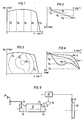
- FIGS. 1 and 2 show the linear injection adjustment speed relationship independent of the torque of the engine, as is done in conventional controls.
- the injection timing curves in the engine map are therefore straight lines over the speed.
- FIGS. 3 and 4 show speed and load-dependent spray adjustments as can be achieved according to the invention.
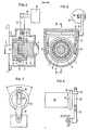
- 5 and 6 show a device for adjusting the angle of rotation between the pump drive and pump camshaft in section
- FIG. 5 showing a section along the line V-V of FIG. 6.
- 7 and 8 show an embodiment of the actuator as a stepper motor
- FIG. 9 shows a schematic overall structure for an injection system
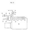
- FIG. 10 shows a schematic representation of the arrangement of the measurement sensors on a diesel engine.
- FIG. 1 the engine speed (min- 1 ) is plotted on the abscissa and the motor torque in nanometers is plotted on the ordinate.
- the spray adjustment at different engine speeds plotted on the negative ordinate axis as camshaft angle in degrees before top dead center of the piston of the internal combustion engine, results in a straight line which is independent of the engine torque in the conventional control.
- FIGS. 3 and 4 show analogous representations for different engine torques, any speed and load-dependent spray adjustments should be possible.
- FIGS. 5 and 6 denotes a housing which is flange-mounted, for example, on the injection pump housing 2.
- the shaft 3 which has an external toothing 4.
- a second shaft 5 is mounted in the shaft 3 and in the housing 1 and also has an external toothing 6.
- the sliding sleeve 7, which has an internal toothing 8 be sits, is longitudinally displaceable via a slide ring 9.
- the servomotor 15 can work according to the hydraulic, pneumatic or electrical principle. The prerequisite is that the servomotor 15 can follow all occurring changes in load and speed of the internal combustion engine.
- FIG. 7 and 8 show exemplary embodiments with a stepper motor 16.
- the stepper motor is distinguished by a high step frequency and high accuracy.
- On the shaft 17 there is a disk 18 in which a bolt 19 is located. This bolt 19 engages in a groove 20 of the outer lever 13.
- the outer lever 13 is now actuated and the required spray adjustment is thus achieved.
- FIG. 9 shows the overall schematic structure for a conventional injection system.
- the invention is not necessarily coupled to such an injection system, but is intended for any injection system.
- a regulator 22 and the attached spray adjuster 23 are located on the pump 21.
- the outer lever 25 of the regulator is now actuated via the driving foot lever 24 and the required engine speed or engine load is thus preselected.
- On the flywheel 26 of the internal combustion engine there is a sensor 27 which measures the speed. This speed is transmitted to the control unit 28.
- the engine torque is determined via a transducer.
- this sensor is indicated schematically at 29.
- the signal from the sensor 29, which is proportional to the load torque, is forwarded to the control unit 28.
- the target injection adjustment characteristic values are stored in the control unit 28.
- the load point in the engine map is precisely defined from the measurement of engine torque and engine speed, and with it the required spray adjustment.
- the control unit 28 now controls the servomotor 15 according to the engine load point, which sets the desired spray adjustment via the outer lever 13.
- the motor is designated 30.
- the intake air enters at 31 and is compressed by an exhaust gas turbocharger 32.
- the boost pressure is registered by the sensor 29, in the case shown a blow-off valve 33 is provided, via which part of the air is blown off again as the speed increases.
- a measurement sensor 34 is fixed, with which the blow-off quantity is determined.
- the exhaust gases emitted by the engine pass through the exhaust manifold 35 and the turbocharger into the exhaust line 36, a further sensor 37 being provided, with which the CO content or the temperature of the exhaust gases can be determined.
- the signals from the measurement sensors 29, 34 and 37 can be fed directly to the microprocessor in the control unit 28, and in this way an exact control signal for the adjustment of the injection timing can be derived in order to achieve particularly favorable emission and consumption values.
- the arbitrary load and speed-dependent spray adjustment is achieved by operating the outer lever of the device in accordance with AT-B No. 298881.
- the speed-dependent spray adjustment can be carried out depending on the speed measuring mechanism shown, for example, in AT-B No. 298881.
- the values for the speed and for load-dependent signals can be combined in any way, so that the special requirements of a particular internal combustion engine can be taken into account to an improved extent.
Landscapes
- Engineering & Computer Science (AREA)
- Chemical & Material Sciences (AREA)
- Combustion & Propulsion (AREA)
- Mechanical Engineering (AREA)
- General Engineering & Computer Science (AREA)
- Electrical Control Of Air Or Fuel Supplied To Internal-Combustion Engine (AREA)
- High-Pressure Fuel Injection Pump Control (AREA)
- Output Control And Ontrol Of Special Type Engine (AREA)
- Combined Controls Of Internal Combustion Engines (AREA)
Priority Applications (1)
| Application Number | Priority Date | Filing Date | Title |
|---|---|---|---|
| AT81890166T ATE8071T1 (de) | 1981-10-08 | 1981-10-08 | Verfahren zur steuerung des foerderbeginns einer einspritzpumpe sowie vorrichtung zur durchfuehrung dieses verfahrens. |
Applications Claiming Priority (2)
| Application Number | Priority Date | Filing Date | Title |
|---|---|---|---|
| AT499980 | 1980-10-08 | ||
| AT4999/80 | 1980-10-08 |
Publications (3)
| Publication Number | Publication Date |
|---|---|
| EP0049703A2 EP0049703A2 (de) | 1982-04-14 |
| EP0049703A3 EP0049703A3 (en) | 1982-09-15 |
| EP0049703B1 true EP0049703B1 (de) | 1984-06-20 |
Family
ID=3570790
Family Applications (4)
| Application Number | Title | Priority Date | Filing Date |
|---|---|---|---|
| EP81890166A Expired EP0049703B1 (de) | 1980-10-08 | 1981-10-08 | Verfahren zur Steuerung des Förderbeginns einer Einspritzpumpe sowie Vorrichtung zur Durchführung dieses Verfahrens |
| EP81890164A Withdrawn EP0049701A3 (de) | 1980-10-08 | 1981-10-08 | Verfahren zur Steuerung des Förderbeginns einer Einspritzpumpe sowie Vorrichtung zur Durchführung dieses Verfahrens |
| EP81890167A Withdrawn EP0049704A3 (de) | 1980-10-08 | 1981-10-08 | Verfahren zur Steuerung des Förderbeginns einer Einspritzpumpe sowie Vorrichtung zur Durchführung dieses Verfahrens |
| EP81890165A Expired EP0049702B1 (de) | 1980-10-08 | 1981-10-08 | Verfahren zur Steuerung des Förderbeginns einer Einspritzpumpe sowie Vorrichtung zur Durchführung dieses Verfahrens |
Family Applications After (3)
| Application Number | Title | Priority Date | Filing Date |
|---|---|---|---|
| EP81890164A Withdrawn EP0049701A3 (de) | 1980-10-08 | 1981-10-08 | Verfahren zur Steuerung des Förderbeginns einer Einspritzpumpe sowie Vorrichtung zur Durchführung dieses Verfahrens |
| EP81890167A Withdrawn EP0049704A3 (de) | 1980-10-08 | 1981-10-08 | Verfahren zur Steuerung des Förderbeginns einer Einspritzpumpe sowie Vorrichtung zur Durchführung dieses Verfahrens |
| EP81890165A Expired EP0049702B1 (de) | 1980-10-08 | 1981-10-08 | Verfahren zur Steuerung des Förderbeginns einer Einspritzpumpe sowie Vorrichtung zur Durchführung dieses Verfahrens |
Country Status (4)
| Country | Link |
|---|---|
| US (1) | US4426982A (OSRAM) |
| EP (4) | EP0049703B1 (OSRAM) |
| JP (4) | JPS5793639A (OSRAM) |
| DE (2) | DE3164329D1 (OSRAM) |
Families Citing this family (46)
| Publication number | Priority date | Publication date | Assignee | Title |
|---|---|---|---|---|
| US4476837A (en) * | 1982-12-07 | 1984-10-16 | Stanadyne, Inc. | Method and system for fuel injection timing |
| JPS60138248A (ja) * | 1983-12-27 | 1985-07-22 | Diesel Kiki Co Ltd | 内燃機関用燃料噴射装置 |
| US4708112A (en) * | 1985-07-11 | 1987-11-24 | Kokusan Denki Co. Ltd. | Electronic governor for an internal combustion engine |
| DE3605824A1 (de) * | 1986-02-22 | 1987-08-27 | Bosch Gmbh Robert | Kraftstoffeinspritzpumpe zur versorgung der brennraeume von fuer fahrzeugantriebe vorgesehenen brennkraftmaschinen |
| DE3771942D1 (de) * | 1986-06-19 | 1991-09-12 | Nippon Clean Engine Res | Brennkraftmaschine mit brennstoffeinspritzung. |
| US4885935A (en) * | 1988-06-27 | 1989-12-12 | Ford Motor Company | Engine testing system |
| JPH0765523B2 (ja) * | 1989-07-20 | 1995-07-19 | 日産自動車株式会社 | ディーゼルエンジンの燃料噴射制御装置 |
| DE4446246C2 (de) * | 1994-12-23 | 1999-10-21 | Mtu Friedrichshafen Gmbh | Verfahren zur Regelung des Lastannahme- und Beschleunigungsverhaltens von aufgeladenen Brennkraftmaschinen |
| DE19535056C2 (de) * | 1995-09-21 | 2000-09-14 | Daimler Chrysler Ag | Verfahren zur Steuerung der Kraftstoffeinspritzung bei einem Dieselmotor |
| US5709196A (en) * | 1996-09-24 | 1998-01-20 | Caterpillar Inc. | Fuel control system for an internal combustion engine using a low cetane quality fuel |
| US6517330B2 (en) * | 2000-05-10 | 2003-02-11 | Kioritz Corporation | Reciprocating pump |
| DE50110631D1 (de) * | 2000-07-07 | 2006-09-14 | Siemens Ag | Verfahren zur regelung eines ladedrucks in einer brennkraftmaschine mit einem abgasturbolader |
| US7743606B2 (en) * | 2004-11-18 | 2010-06-29 | Honeywell International Inc. | Exhaust catalyst system |
| US7182075B2 (en) * | 2004-12-07 | 2007-02-27 | Honeywell International Inc. | EGR system |
| US7591135B2 (en) * | 2004-12-29 | 2009-09-22 | Honeywell International Inc. | Method and system for using a measure of fueling rate in the air side control of an engine |
| US7467614B2 (en) | 2004-12-29 | 2008-12-23 | Honeywell International Inc. | Pedal position and/or pedal change rate for use in control of an engine |
| US7275374B2 (en) * | 2004-12-29 | 2007-10-02 | Honeywell International Inc. | Coordinated multivariable control of fuel and air in engines |
| US7328577B2 (en) | 2004-12-29 | 2008-02-12 | Honeywell International Inc. | Multivariable control for an engine |
| US7165399B2 (en) * | 2004-12-29 | 2007-01-23 | Honeywell International Inc. | Method and system for using a measure of fueling rate in the air side control of an engine |
| US20060168945A1 (en) * | 2005-02-02 | 2006-08-03 | Honeywell International Inc. | Aftertreatment for combustion engines |
| US7752840B2 (en) * | 2005-03-24 | 2010-07-13 | Honeywell International Inc. | Engine exhaust heat exchanger |
| US7469177B2 (en) * | 2005-06-17 | 2008-12-23 | Honeywell International Inc. | Distributed control architecture for powertrains |
| US7389773B2 (en) | 2005-08-18 | 2008-06-24 | Honeywell International Inc. | Emissions sensors for fuel control in engines |
| US7155334B1 (en) | 2005-09-29 | 2006-12-26 | Honeywell International Inc. | Use of sensors in a state observer for a diesel engine |
| US7765792B2 (en) * | 2005-10-21 | 2010-08-03 | Honeywell International Inc. | System for particulate matter sensor signal processing |
| US7357125B2 (en) * | 2005-10-26 | 2008-04-15 | Honeywell International Inc. | Exhaust gas recirculation system |
| US20070144149A1 (en) * | 2005-12-28 | 2007-06-28 | Honeywell International Inc. | Controlled regeneration system |
| US7415389B2 (en) * | 2005-12-29 | 2008-08-19 | Honeywell International Inc. | Calibration of engine control systems |
| US8060290B2 (en) | 2008-07-17 | 2011-11-15 | Honeywell International Inc. | Configurable automotive controller |
| US8620461B2 (en) | 2009-09-24 | 2013-12-31 | Honeywell International, Inc. | Method and system for updating tuning parameters of a controller |
| US8504175B2 (en) | 2010-06-02 | 2013-08-06 | Honeywell International Inc. | Using model predictive control to optimize variable trajectories and system control |
| US9677493B2 (en) | 2011-09-19 | 2017-06-13 | Honeywell Spol, S.R.O. | Coordinated engine and emissions control system |
| US9650934B2 (en) | 2011-11-04 | 2017-05-16 | Honeywell spol.s.r.o. | Engine and aftertreatment optimization system |
| US20130111905A1 (en) | 2011-11-04 | 2013-05-09 | Honeywell Spol. S.R.O. | Integrated optimization and control of an engine and aftertreatment system |
| EP3051367B1 (en) | 2015-01-28 | 2020-11-25 | Honeywell spol s.r.o. | An approach and system for handling constraints for measured disturbances with uncertain preview |
| EP3056706A1 (en) | 2015-02-16 | 2016-08-17 | Honeywell International Inc. | An approach for aftertreatment system modeling and model identification |
| EP3091212A1 (en) | 2015-05-06 | 2016-11-09 | Honeywell International Inc. | An identification approach for internal combustion engine mean value models |
| EP3125052B1 (en) | 2015-07-31 | 2020-09-02 | Garrett Transportation I Inc. | Quadratic program solver for mpc using variable ordering |
| US10272779B2 (en) | 2015-08-05 | 2019-04-30 | Garrett Transportation I Inc. | System and approach for dynamic vehicle speed optimization |
| US10415492B2 (en) | 2016-01-29 | 2019-09-17 | Garrett Transportation I Inc. | Engine system with inferential sensor |
| US10036338B2 (en) | 2016-04-26 | 2018-07-31 | Honeywell International Inc. | Condition-based powertrain control system |
| US10124750B2 (en) | 2016-04-26 | 2018-11-13 | Honeywell International Inc. | Vehicle security module system |
| EP3548729B1 (en) | 2016-11-29 | 2023-02-22 | Garrett Transportation I Inc. | An inferential flow sensor |
| US10591003B2 (en) | 2017-06-16 | 2020-03-17 | Polaris Industries Inc. | Brake assembly shield and scraper |
| US11057213B2 (en) | 2017-10-13 | 2021-07-06 | Garrett Transportation I, Inc. | Authentication system for electronic control unit on a bus |
| US11293372B1 (en) | 2020-09-30 | 2022-04-05 | Ford Global Technologies, Llc | Method and system for adjusting operation of a fuel injector |
Family Cites Families (19)
| Publication number | Priority date | Publication date | Assignee | Title |
|---|---|---|---|---|
| CA862492A (en) | 1971-02-02 | D. Mcdowell Robert | Engine fuel injection timing device | |
| US1718586A (en) | 1925-12-10 | 1929-06-25 | Motorenfabrik Deutz Ag | Governing system for diesel engines with arrangements to work with increased admission pressure (supercharging) |
| US2270410A (en) | 1938-06-01 | 1942-01-20 | Atlas Diesel Ab | Means for automatically controlling the fuel injecting mechanism of internal combustion engines |
| GB1322502A (en) * | 1969-06-30 | 1973-07-04 | Cav Ltd | Compression ignition engine fuel systems |
| DE2011712C3 (de) * | 1970-03-12 | 1979-07-12 | Robert Bosch Gmbh, 7000 Stuttgart | Kraftstoff-Einspritzanlage einer Dieselbrennkraftmaschine |
| FR2098627A5 (OSRAM) * | 1970-07-22 | 1972-03-10 | Bowles Fluidics Corp | |
| US3897766A (en) * | 1971-05-10 | 1975-08-05 | Massachusetts Inst Technology | Apparatus adapted to opto-electrically monitor the output of a prime mover to provide signals which are fed back to the input and thereby provide control of the prime mover |
| US3742925A (en) | 1971-07-19 | 1973-07-03 | Caterpillar Tractor Co | Timing mechanism for engines |
| GB1429302A (en) * | 1972-04-04 | 1976-03-24 | Cav Ltd | Control systems for fuel supply systems for engines |
| GB1413099A (en) * | 1974-03-05 | 1975-11-05 | Fiat Spa | Electronic injection timing control for fuel injection pumps |
| GB1520427A (en) * | 1974-07-19 | 1978-08-09 | Bosch Gmbh Robert | Process of and system for regulating the operating behavaiour of an internal combustion engine |
| JPS5139285A (ja) * | 1974-09-20 | 1976-04-01 | Katsumi Konno | Jidoteijikyujiki |
| US4023403A (en) * | 1975-07-11 | 1977-05-17 | Scans Associates, Inc. | Method and apparatus for timing diesel engines |
| JPS5351945Y2 (OSRAM) * | 1975-07-26 | 1978-12-12 | ||
| US4166440A (en) * | 1977-09-29 | 1979-09-04 | The Bendix Corporation | Engine control system utilizing torque converter slip |
| FR2417642A1 (fr) * | 1978-02-20 | 1979-09-14 | List Hans | Moteur a injection de carburant, notamment moteur diesel avec installation de reglage de l'instant d'injection |
| GB2024462B (en) * | 1978-05-08 | 1983-03-30 | Bendix Corp | Integrated closed loop engine control system |
| DE2923445C2 (de) | 1979-06-09 | 1987-01-22 | Robert Bosch Gmbh, 7000 Stuttgart | Steuereinrichtung für die Änderung des Förderbeginns einer Kraftstoffeinspritzpumpe einer Brennkraftmaschine |
| DE2943950A1 (de) * | 1979-10-31 | 1981-05-14 | Robert Bosch Gmbh, 7000 Stuttgart | Verfahren zur verbesserung des beschleunigungsverhaltens einer mit einem abgasturbolader betriebenen brennkraftmaschine |
-
1981
- 1981-10-02 US US06/307,939 patent/US4426982A/en not_active Expired - Fee Related
- 1981-10-07 JP JP56158908A patent/JPS5793639A/ja active Granted
- 1981-10-07 JP JP56158909A patent/JPS5793640A/ja active Granted
- 1981-10-07 JP JP56158907A patent/JPS5793638A/ja active Pending
- 1981-10-07 JP JP56158910A patent/JPS5793641A/ja active Pending
- 1981-10-08 DE DE8181890166T patent/DE3164329D1/de not_active Expired
- 1981-10-08 EP EP81890166A patent/EP0049703B1/de not_active Expired
- 1981-10-08 EP EP81890164A patent/EP0049701A3/de not_active Withdrawn
- 1981-10-08 DE DE8181890165T patent/DE3164206D1/de not_active Expired
- 1981-10-08 EP EP81890167A patent/EP0049704A3/de not_active Withdrawn
- 1981-10-08 EP EP81890165A patent/EP0049702B1/de not_active Expired
Also Published As
| Publication number | Publication date |
|---|---|
| JPS5793639A (en) | 1982-06-10 |
| EP0049702A3 (en) | 1982-09-22 |
| EP0049703A3 (en) | 1982-09-15 |
| JPS6225857B2 (OSRAM) | 1987-06-05 |
| EP0049701A3 (de) | 1982-09-15 |
| DE3164329D1 (en) | 1984-07-26 |
| EP0049704A2 (de) | 1982-04-14 |
| EP0049701A2 (de) | 1982-04-14 |
| EP0049702B1 (de) | 1984-06-13 |
| US4426982A (en) | 1984-01-24 |
| JPS5793638A (en) | 1982-06-10 |
| EP0049702A2 (de) | 1982-04-14 |
| EP0049703A2 (de) | 1982-04-14 |
| JPS5793640A (en) | 1982-06-10 |
| DE3164206D1 (en) | 1984-07-19 |
| EP0049704A3 (de) | 1982-09-15 |
| JPS6225856B2 (OSRAM) | 1987-06-05 |
| JPS5793641A (en) | 1982-06-10 |
Similar Documents
| Publication | Publication Date | Title |
|---|---|---|
| EP0049703B1 (de) | Verfahren zur Steuerung des Förderbeginns einer Einspritzpumpe sowie Vorrichtung zur Durchführung dieses Verfahrens | |
| DE69404630T2 (de) | Abgasturbolader für brennkraftmaschinen | |
| DE3204918A1 (de) | Verfahren und system zum steuern des einlassdruckes bei einem verbrennungsmotor | |
| DE4330368A1 (de) | Verfahren und Vorrichtung zur Steuerung der Antriebsleistung eines Fahrzeugs | |
| DE3020131A1 (de) | Vorrichtung zur luftdurchsatzsteuerung bei einem brennkraftmotor | |
| DE3522414A1 (de) | Treibstoff-einspritzsystem fuer verbrennungsmotoren | |
| DE19727866C2 (de) | Einrichtung zum Steuern einer Brennkraftmaschine | |
| DE10319666A1 (de) | Verfahren und Vorrichtung zur Einstellung einer variablen Verdichtung bei einem Verbrennungsmotor | |
| EP0067369B1 (de) | Kraftstoffeinspritzeinrichtung für Brennkraftmaschinen | |
| DE69033251T2 (de) | Luftzufuhrsystem für verbrennungsmotor | |
| EP1152128B1 (de) | Verfahren und Vorrichtung zur elektronischen Steuerung von Aktuatoren einer Brennkraftmaschine mit variabler Gaswechselsteuerung | |
| EP1611318B1 (de) | Verfahren zum steuern einer brennkraftmaschine | |
| EP1849979B1 (de) | Kolbenmotor und zugehöriges Betriebsverfahren | |
| DE19650249A1 (de) | Einrichtung zur Erfassung des Verdrehwinkels und/oder des Ventilhubes bei einer mehrzylindrigen Brennkraftmaschine | |
| EP0085082A1 (de) | Verbindungseinrichtung zwischen einem leistungssteuerglied einer brennkraftmaschine und einem betätigungsglied | |
| DE19534878B4 (de) | Verfahren zur automatischen Kalibrierung eines Winkelmarkengebers an der Kurbelwelle einer Kolbenbrennkraftmaschine | |
| DE3701170A1 (de) | Lufteinlassvorrichtung fuer einen dieselmotor | |
| EP1273795B1 (de) | Verfahren und Vorrichtung zum Einspritzen von Kraftstoff | |
| DE3242833A1 (de) | Vorrichtung zur kraftstoff- und luftzufuehrung fuer brennkraftmaschinen | |
| EP0044289A1 (de) | Einrichtung zum Steuern und Regeln des Verstellweges der Regelstange einer Einspritzbrennkraftmaschine in Abhängigkeit von Betriebsgrössen | |
| EP2236798B1 (de) | Verfahren und Vorrichtung zur Diagnose eines variablen Ventiltriebs einer Brennkraftmaschine | |
| EP1429007A2 (de) | Verfahren zum Einstellen einer Abgasrückführrate | |
| DE102014217563B3 (de) | Verfahren und Vorrichtung zur Verbesserung der in den Zylindern einer Brennkraftmaschine erfolgenden Verbrennungsvorgänge mittels einer Nockenwellenverstellung | |
| DE102017205034B4 (de) | Verfahren zum Betreiben einer Brennkraftmaschine und Brennkraftmaschine | |
| DE921292C (de) | Gemischregler fuer gemischverdichtende Einspritz-Brennkraftmaschinen |
Legal Events
| Date | Code | Title | Description |
|---|---|---|---|
| PUAI | Public reference made under article 153(3) epc to a published international application that has entered the european phase |
Free format text: ORIGINAL CODE: 0009012 |
|
| AK | Designated contracting states |
Designated state(s): AT DE FR GB |
|
| PUAL | Search report despatched |
Free format text: ORIGINAL CODE: 0009013 |
|
| AK | Designated contracting states |
Designated state(s): AT DE FR GB |
|
| 17P | Request for examination filed |
Effective date: 19821021 |
|
| GRAA | (expected) grant |
Free format text: ORIGINAL CODE: 0009210 |
|
| AK | Designated contracting states |
Designated state(s): AT DE FR GB |
|
| REF | Corresponds to: |
Ref document number: 8071 Country of ref document: AT Date of ref document: 19840715 Kind code of ref document: T |
|
| REF | Corresponds to: |
Ref document number: 3164329 Country of ref document: DE Date of ref document: 19840726 |
|
| ET | Fr: translation filed | ||
| PGFP | Annual fee paid to national office [announced via postgrant information from national office to epo] |
Ref country code: FR Payment date: 19841022 Year of fee payment: 4 |
|
| PGFP | Annual fee paid to national office [announced via postgrant information from national office to epo] |
Ref country code: DE Payment date: 19841221 Year of fee payment: 4 |
|
| PLBE | No opposition filed within time limit |
Free format text: ORIGINAL CODE: 0009261 |
|
| STAA | Information on the status of an ep patent application or granted ep patent |
Free format text: STATUS: NO OPPOSITION FILED WITHIN TIME LIMIT |
|
| 26N | No opposition filed | ||
| PGFP | Annual fee paid to national office [announced via postgrant information from national office to epo] |
Ref country code: AT Payment date: 19861007 Year of fee payment: 6 |
|
| PG25 | Lapsed in a contracting state [announced via postgrant information from national office to epo] |
Ref country code: GB Effective date: 19881008 Ref country code: AT Effective date: 19881008 |
|
| PG25 | Lapsed in a contracting state [announced via postgrant information from national office to epo] |
Ref country code: FR Free format text: LAPSE BECAUSE OF NON-PAYMENT OF DUE FEES Effective date: 19890630 |
|
| PG25 | Lapsed in a contracting state [announced via postgrant information from national office to epo] |
Ref country code: DE Effective date: 19890701 |
|
| GBPC | Gb: european patent ceased through non-payment of renewal fee | ||
| REG | Reference to a national code |
Ref country code: FR Ref legal event code: ST |