EP0048833A2 - Fräswerkzeug - Google Patents
Fräswerkzeug Download PDFInfo
- Publication number
- EP0048833A2 EP0048833A2 EP81106795A EP81106795A EP0048833A2 EP 0048833 A2 EP0048833 A2 EP 0048833A2 EP 81106795 A EP81106795 A EP 81106795A EP 81106795 A EP81106795 A EP 81106795A EP 0048833 A2 EP0048833 A2 EP 0048833A2
- Authority
- EP
- European Patent Office
- Prior art keywords
- cutting knife
- knife holder
- milling tool
- recess
- eccentric
- Prior art date
- Legal status (The legal status is an assumption and is not a legal conclusion. Google has not performed a legal analysis and makes no representation as to the accuracy of the status listed.)
- Granted
Links
Images

Classifications
-
- B—PERFORMING OPERATIONS; TRANSPORTING
- B23—MACHINE TOOLS; METAL-WORKING NOT OTHERWISE PROVIDED FOR
- B23C—MILLING
- B23C5/00—Milling-cutters
- B23C5/16—Milling-cutters characterised by physical features other than shape
- B23C5/20—Milling-cutters characterised by physical features other than shape with removable cutter bits or teeth or cutting inserts
- B23C5/22—Securing arrangements for bits or teeth or cutting inserts
- B23C5/24—Securing arrangements for bits or teeth or cutting inserts adjustable
- B23C5/2479—Securing arrangements for bits or teeth or cutting inserts adjustable the adjusting means being eccentrics
-
- B—PERFORMING OPERATIONS; TRANSPORTING
- B23—MACHINE TOOLS; METAL-WORKING NOT OTHERWISE PROVIDED FOR
- B23C—MILLING
- B23C5/00—Milling-cutters
- B23C5/16—Milling-cutters characterised by physical features other than shape
- B23C5/20—Milling-cutters characterised by physical features other than shape with removable cutter bits or teeth or cutting inserts
- B23C5/22—Securing arrangements for bits or teeth or cutting inserts
- B23C5/2265—Securing arrangements for bits or teeth or cutting inserts by means of a wedge
- B23C5/2278—Securing arrangements for bits or teeth or cutting inserts by means of a wedge for plate-like cutting inserts fitted on an intermediate carrier, e.g. shank fixed in the cutter body
-
- B—PERFORMING OPERATIONS; TRANSPORTING
- B23—MACHINE TOOLS; METAL-WORKING NOT OTHERWISE PROVIDED FOR
- B23C—MILLING
- B23C5/00—Milling-cutters
- B23C5/16—Milling-cutters characterised by physical features other than shape
- B23C5/20—Milling-cutters characterised by physical features other than shape with removable cutter bits or teeth or cutting inserts
- B23C5/22—Securing arrangements for bits or teeth or cutting inserts
- B23C5/24—Securing arrangements for bits or teeth or cutting inserts adjustable
- B23C5/2472—Securing arrangements for bits or teeth or cutting inserts adjustable the adjusting means being screws
-
- B—PERFORMING OPERATIONS; TRANSPORTING
- B23—MACHINE TOOLS; METAL-WORKING NOT OTHERWISE PROVIDED FOR
- B23C—MILLING
- B23C5/00—Milling-cutters
- B23C5/16—Milling-cutters characterised by physical features other than shape
- B23C5/20—Milling-cutters characterised by physical features other than shape with removable cutter bits or teeth or cutting inserts
- B23C5/22—Securing arrangements for bits or teeth or cutting inserts
- B23C5/24—Securing arrangements for bits or teeth or cutting inserts adjustable
- B23C5/2486—Securing arrangements for bits or teeth or cutting inserts adjustable where the adjustment is made by elastically deforming the toolholders
-
- B—PERFORMING OPERATIONS; TRANSPORTING
- B23—MACHINE TOOLS; METAL-WORKING NOT OTHERWISE PROVIDED FOR
- B23C—MILLING
- B23C2200/00—Details of milling cutting inserts
- B23C2200/12—Side or flank surfaces
- B23C2200/125—Side or flank surfaces discontinuous
-
- B—PERFORMING OPERATIONS; TRANSPORTING
- B23—MACHINE TOOLS; METAL-WORKING NOT OTHERWISE PROVIDED FOR
- B23C—MILLING
- B23C2200/00—Details of milling cutting inserts
- B23C2200/16—Supporting or bottom surfaces
- B23C2200/165—Supporting or bottom surfaces with one or more grooves
-
- B—PERFORMING OPERATIONS; TRANSPORTING
- B23—MACHINE TOOLS; METAL-WORKING NOT OTHERWISE PROVIDED FOR
- B23C—MILLING
- B23C2200/00—Details of milling cutting inserts
- B23C2200/20—Top or side views of the cutting edge
- B23C2200/201—Details of the nose radius and immediately surrounding areas
-
- Y—GENERAL TAGGING OF NEW TECHNOLOGICAL DEVELOPMENTS; GENERAL TAGGING OF CROSS-SECTIONAL TECHNOLOGIES SPANNING OVER SEVERAL SECTIONS OF THE IPC; TECHNICAL SUBJECTS COVERED BY FORMER USPC CROSS-REFERENCE ART COLLECTIONS [XRACs] AND DIGESTS
- Y10—TECHNICAL SUBJECTS COVERED BY FORMER USPC
- Y10T—TECHNICAL SUBJECTS COVERED BY FORMER US CLASSIFICATION
- Y10T407/00—Cutters, for shaping
- Y10T407/19—Rotary cutting tool
- Y10T407/1906—Rotary cutting tool including holder [i.e., head] having seat for inserted tool
- Y10T407/1908—Face or end mill
- Y10T407/1912—Tool adjustable relative to holder
- Y10T407/1914—Radially
- Y10T407/1916—And axially
- Y10T407/1918—Selectively
-
- Y—GENERAL TAGGING OF NEW TECHNOLOGICAL DEVELOPMENTS; GENERAL TAGGING OF CROSS-SECTIONAL TECHNOLOGIES SPANNING OVER SEVERAL SECTIONS OF THE IPC; TECHNICAL SUBJECTS COVERED BY FORMER USPC CROSS-REFERENCE ART COLLECTIONS [XRACs] AND DIGESTS
- Y10—TECHNICAL SUBJECTS COVERED BY FORMER USPC
- Y10T—TECHNICAL SUBJECTS COVERED BY FORMER US CLASSIFICATION
- Y10T407/00—Cutters, for shaping
- Y10T407/19—Rotary cutting tool
- Y10T407/1906—Rotary cutting tool including holder [i.e., head] having seat for inserted tool
- Y10T407/1908—Face or end mill
- Y10T407/192—Face or end mill with separate means to fasten tool to holder
- Y10T407/1922—Wedge clamp element
-
- Y—GENERAL TAGGING OF NEW TECHNOLOGICAL DEVELOPMENTS; GENERAL TAGGING OF CROSS-SECTIONAL TECHNOLOGIES SPANNING OVER SEVERAL SECTIONS OF THE IPC; TECHNICAL SUBJECTS COVERED BY FORMER USPC CROSS-REFERENCE ART COLLECTIONS [XRACs] AND DIGESTS
- Y10—TECHNICAL SUBJECTS COVERED BY FORMER USPC
- Y10T—TECHNICAL SUBJECTS COVERED BY FORMER US CLASSIFICATION
- Y10T407/00—Cutters, for shaping
- Y10T407/19—Rotary cutting tool
- Y10T407/1906—Rotary cutting tool including holder [i.e., head] having seat for inserted tool
- Y10T407/1932—Rotary cutting tool including holder [i.e., head] having seat for inserted tool with means to fasten tool seat to holder
-
- Y—GENERAL TAGGING OF NEW TECHNOLOGICAL DEVELOPMENTS; GENERAL TAGGING OF CROSS-SECTIONAL TECHNOLOGIES SPANNING OVER SEVERAL SECTIONS OF THE IPC; TECHNICAL SUBJECTS COVERED BY FORMER USPC CROSS-REFERENCE ART COLLECTIONS [XRACs] AND DIGESTS
- Y10—TECHNICAL SUBJECTS COVERED BY FORMER USPC
- Y10T—TECHNICAL SUBJECTS COVERED BY FORMER US CLASSIFICATION
- Y10T407/00—Cutters, for shaping
- Y10T407/19—Rotary cutting tool
- Y10T407/1906—Rotary cutting tool including holder [i.e., head] having seat for inserted tool
- Y10T407/1934—Rotary cutting tool including holder [i.e., head] having seat for inserted tool with separate means to fasten tool to holder
- Y10T407/1938—Wedge clamp element
-
- Y—GENERAL TAGGING OF NEW TECHNOLOGICAL DEVELOPMENTS; GENERAL TAGGING OF CROSS-SECTIONAL TECHNOLOGIES SPANNING OVER SEVERAL SECTIONS OF THE IPC; TECHNICAL SUBJECTS COVERED BY FORMER USPC CROSS-REFERENCE ART COLLECTIONS [XRACs] AND DIGESTS
- Y10—TECHNICAL SUBJECTS COVERED BY FORMER USPC
- Y10T—TECHNICAL SUBJECTS COVERED BY FORMER US CLASSIFICATION
- Y10T408/00—Cutting by use of rotating axially moving tool
- Y10T408/83—Tool-support with means to move Tool relative to tool-support
- Y10T408/85—Tool-support with means to move Tool relative to tool-support to move radially
- Y10T408/858—Moving means including wedge, screw or cam
- Y10T408/859—Rotary cam
-
- Y—GENERAL TAGGING OF NEW TECHNOLOGICAL DEVELOPMENTS; GENERAL TAGGING OF CROSS-SECTIONAL TECHNOLOGIES SPANNING OVER SEVERAL SECTIONS OF THE IPC; TECHNICAL SUBJECTS COVERED BY FORMER USPC CROSS-REFERENCE ART COLLECTIONS [XRACs] AND DIGESTS
- Y10—TECHNICAL SUBJECTS COVERED BY FORMER USPC
- Y10T—TECHNICAL SUBJECTS COVERED BY FORMER US CLASSIFICATION
- Y10T408/00—Cutting by use of rotating axially moving tool
- Y10T408/86—Tool-support with means to permit positioning of the Tool relative to support
- Y10T408/865—Pivotable Tool
- Y10T408/868—Pivotable Tool with multiple cutting positions
Definitions
- the invention relates to a milling tool of the type mentioned in the preamble of the main claim.
- Milling tools of this type are known. With them, the cutting knife holder is supported on the bottom of the recess receiving the holder, which is inclined at approximately 15-20 ° against the longitudinal axis of the tool. When the knife holder is axially adjusted, radial adjustment is therefore inevitably also effected.
- the object of the invention is to create a milling tool of the type mentioned with a longer service life for the cutting edges of the cutting knives and greater setting options and greater precision in the setting of the cutting knives.
- the setting should be possible in a short time; the means provided for this purpose should be structurally simple and cheap.
- the milling tool according to the invention offers the advantage of being able to precisely adjust the radial distance of the main and secondary cutting edges of the cutting knives on the milling tool in a short time with the aid of two screws which are adjustable in their longitudinal direction, without having to make any axial adjustment.
- the cutting knife holder can be tilted such that the main cutting edge can be given a selectable angular position in relation to the longitudinal axis of the tool.
- the cylindrical tool 1 carries at a uniform angular distance on its periphery recesses 2, of which only one is shown in the drawing.
- the recess is inclined with respect to the longitudinal axis L of the tool or a parallel to it; it is delimited by the base 3 and the two side walls 4, 5, of which the side wall 4 merges into the bevel 6.
- the side wall 5 is laterally followed by the recess 7 for the cutting knife holder, which runs parallel to the recess 2 and whose bottom 8 and thus the recess 7 itself corresponds to the width of the cutting knife holder, which will be described in more detail below.
- the contour of the side wall 9 of the recess 7 corresponds to that of the cutting knife holder and the tool 1.
- the bottom 8 thereof has two narrow recesses or grooves 10, 11 which are offset from one another in the longitudinal direction of the recess 7 and whose bottom 12, 13 is inclined to the bottom 8 and parallel to the longitudinal axis L of the tool to the bottom 3 of the recess 2 parallel bottom 8 of the recess 7 extends approximately in *
- the center of which in the radial direction of the tool has a blind bore 15 into which the pin 16 of a truncated cone-shaped eccentric head 17 projects.
- This pin carries an annular constriction 18, in which the foot 19 of the locking pin 20 can engage for the purpose of securing the centrifugal force of the eccentric formed from the parts 16, 17, which is under the action of the spring, the second abutment of which is formed by a grub screw 22.
- the pin 20, the spring 21 and the grub screw 22 can be screwed into a threaded bore 23 in the direction of the arrow 24 (FIG. 2) in the tool 1 such that the eccentric head 17 can be rotated about the axis 25 of the pin 16, however, the grub screw 22 is held in place.
- the side wall 9 can be provided with a bulge 26 (FIGS. 1 and 2). Due to the design of the eccentric head 17 and the recess 32 of the cutting knife holder receiving it and the securing pin 21, an additional centrifugal force safeguard is created in addition to the clamping securing of the cutting knife Sch and the cutting knife holder described in more detail below.
- the cutting knife holder 30 used has the underside 31, from which a dovetail-shaped incision 32 extends, into which the frustoconical eccentric head 17 is able to engage.
- the incision 32 has an oversize in relation to the eccentric head 17, without the adjustment movement of the cutting knife holder being impaired thereby (FIG. 7).
- the bores 34, 38 lie at right angles to the bottoms 12, 13 of the groove or recess 11, 12 of the bottom 8 of the recess 7.
- the ends 36, 40 can therefore be supported in the direction of a normal on the said bottoms if the grub screws are removed their bores 34, 38 are screwed in and out.
- the holding piece 43 is held on the cutting knife holder 30 by means of a leaf spring 42 inserted into a slot. This protrudes resiliently into a recess 44 of the cutting knife holder, which is delimited by the wall 45 and the bottom 46 (FIG. 6).
- the size of the recess corresponds to the cutting knife Sch to be accommodated.
- the recess 44 and the holder piece 43 are dimensioned such that the outside 47 cuts off with the wall 48 of the cutting knife holder 30, from the beveled top 33 a bore 49 extends through which a suitable tool can be inserted, the head of which in the polygonal recess 50 of the Eccentric 17 can be inserted (Fig. 7), thereby rotating the eccentric about the axis 25 of its pin 16.
- the cutting knife holder 30 is held by two clamping pieces 51, 52 (FIGS. 11 and 12), which are accommodated in the recess 2 of the tool and whose side surfaces 53, 54 against the Lateral wall of the cutting knife holder 30 and abut against the holding piece 43 and hold the two parts mentioned in position.
- the two clamping pieces 51, 52 are provided with a threaded bore 55, 56, through which protrudes into an internal polygonal screw 57, 58 provided with opposing threads, which can be screwed with its second thread into bores 59, 60 which extend from the bottom 2 of the recess 3 of the tool are directed radially inwards.
- the cutting knife Sch has, as a cutting knife, a groove 70 which extends over part of the cutting knife and into which the head of a pin 71, which is inserted in the holder 30, projects.
- the main cutting edge 100 and the secondary cutting edge 101 can be given a specific position with respect to the axes a, b of the tool. This position can be shown on the screen 102 shown in FIG. 13 of a transmitted light projector.
- the corner edge 103 between the main and minor cutting edge is used for orientation with respect to the crosshair M.
- this corner edge 103 is axially offset with respect to the crosshair M.
- the corner edge is 103 in the direction of the arrow S offset from the crosshair M.
- the cutting knife holder 30 can be adjusted radially in the direction of the arrow .K such that the corner edge 103 is again at the level of the cross hair M and the cutting knife has the position Sch in solid line in FIG. 13.
- the cutting knife can also be brought into the position Sch" "inclined to the axes a, b of the crosshair by actuating the eccentric head 17 for adjustment in the direction of the axis B, the two Screws 35, 39 first jointly determine the radial position in the direction of arrow K, but then one of the screws or both screws are adjusted independently of one another in such a way that the cutting knife receives its inclined position Sch "'.
Landscapes
- Engineering & Computer Science (AREA)
- Mechanical Engineering (AREA)
- Milling Processes (AREA)
- Cutting Tools, Boring Holders, And Turrets (AREA)
Abstract
Description
- Die Erfindung bezieht sich auf ein Fräswerkzeug der im Oberbegriff des Hauptanspruches genannten Art.
- Derartige Fräswerkzeuge sind bekannt.- Bei ihnen stützt sich der Schneidmesserhalter auf dem unter ca. 15 - 20° gegen die Längsachse des Werkzeuges geneigten Boden der den Halter aufnehmenden Ausnehmung ab. Beim axialen Verstellen des Messerhalters wird daher zwangsläufig auch ein radiales Verstellen bewirkt.
- Diesen bekannten Fräswerkzeugen gegenüber liegt der Erfindung die Aufgabe zugrunde, ein Fräswerkzeug der genannten Art mit höherer Standzeit der Schneiden der Schneidmesser und größere Einstellmöglichkeiten sowie höhere Präzision der Einstellung der Schneidmesser zu schaffen. Die Einstellung soll in kurzer Zeit möglich sein; die hierzu vorgesehenen Mittel sollen konstruktiv einfach und billig sein.
- Zur Lösung dieser Aufgabe sind die Merkmale des kennzeichnenden Teils des Hauptanspruches vorgesehen.- Die Merkmale der Unteransprüche dienen der weiteren Ausgestaltung und Verbesserung der Merkmale des Hauptanspruches. Soweit die Unteransprüche bekannte Merkmale enthalten, sollen diese nur in Verbindung mit den Merkmalen eines vorhergehenden Anspruches Gültigkeit besitzen.
- Das erfindungsgemäße Fräswerkzeug bietet den Vorteil, mit Hilfe zweier in ihrer Längsrichtung verstellbarer Schrauben den radialen Abstand der Haupt- und Nebenschneiden der Schneidmesser an dem Fräswerkzeug in kurzer Zeit genau einstellen zu können, ohne hierbei eine axiale Verstellung vornehmen zu müssen. Darüber hinaus aber kann der Schneidmesserhalter derart gekippt werden, daß der Hauptschneide eine wählbare Winkelstellung zur Werkzeuglängsachse gegeben werden kann.
- Auf der Zeichnung ist ein Ausführungsbeispiel des Schneidwerkzeuges nach der Erfindung dargestellt und zwar zeigt
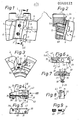
- Fig. 1 eine Draufsicht in radialer Richtung auf einen Abschnitt des Werkzeuges mit der den Schneidmesserhalter sowie die Klemmstücke aufnehmenden Ausnehmung,
- Fig. 2 einen Schnitt nach der Linie II - II der Fig. 1,
- Fig. 3 eine Ansicht des Fräswerkzeugabschnittes in Richtung des Pfeiles III der Fig. 1,
- Fig. 4 den Schneidmesserhalter in Seitenansicht,
- Fig. 5 denselben Halter in der Ansicht gegen seine Unterseite in Richtung des Pfeiles V in Figur 4,
- Fig. 6 eine Draufsicht auf den Schneidmesserhalter in Richtung des Pfeiles VI in Figur 4,
- Fig. 7 das Eingreifen des Exzenters in die entsprechende Ausnehmung des Schneidmesserhalters,
- Fig. 8 die stirnseitige Ansicht des Schneidmesserhalters mit der, das Schneidmesser ausnehmenden Ausnehmung,
- Fig. 9 die, den Exzenter in dem Fräswerkzeug haltende Schraube mit Feder- und Haltestift,
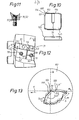
- Fig. 10 ein zur Anwendung gelangendes Schneidmesser in Draufsicht, von hinten und von der Seite,
- Fig. 11 einen Schnitt durch eins der beiden Klemmstücke,
- Fig. 12 eine Ansicht in radialer Richtung des Werkzeugabschnittes gemäß Fig. 1 mit dem eingesetzten Schneidmesserhalter sowie den beiden Klemmstücken,
- Fig. 13 das in einem Durchsichtprojektor erkennbare Bild einer Schneidmesserecke mit den Möglichkeiten der Verstellung des Schneidmessers in axialer und radialer Richtung gegenüber dem Fräswerkzeug sowie in eine geneigte Lage gegenüber der Radialen des Fräswerkzeuges,
- Fig. 14 einen Schnitt durch den Schneidmesserhalter in seinen verschiedenen einstellbaren Lagen und
- Fig. 15 den Exzenter mit seinem pilzartigen Kopf in der entsprechenden Ausnehmung des Schneidmesserhalters.
- Das zylindrische Werkzeug 1 trägt in gleichmäßigem winkelmäßigem Abstand an seinem Umfang Ausnehmungen 2, von denen jeweils in der Zeichnung nur immer eine dargestellt ist. Die Ausnehmung verläuft gegenüber der Längsachse L des Werkzeuges, bzw. einer Parallelen hierzu geneigt; sie wird von dem Boden 3 und den beiden Seitenwänden 4,5 begrenzt, von denen die Seitenwand 4 in die Abschrägung 6 übergeht. An die Seitenwand 5 schließt sich seitlich die Ausnehmung 7 für den Schneidmesserhalter an, die parallel zu der Ausnehmung 2 verläuft und deren Boden 8 und somit die Ausnehmung 7 selbst der Breite des Schneidmesserhalters entspricht, der unten noch näher beschrieben wird. Die Seitenwand 9 der Ausnehmung 7 entspricht in ihrer Kontur der des Schneidmesserhalters und des Werkzeuges 1.
- In Längsrichtung der Ausnehmung 7 weist deren Boden 8 zwei schmale Ausnehmungen oder Nuten 10, 11 auf, die in Längsrichtung der Ausnehmung 7 gegeneinander versetzt sind und deren Boden 12, 13 geneigt zum Boden 8 und parallel zur Längsachse L des Werkzeuges verläuft.- Von dem zu dem Boden 3 der Ausnehmung 2 parallelen Boden 8 der Ausnehmung 7 erstreckt sich etwa in * aus
- deren Mitte in radialer Richtung des Werkzeuges eine Sackbohrung 15, in die der Zapfen 16 eines kegelstumpfförmigen Exzenterkopfes 17 hineinragt. Dieser Zapfen trägt eine ringförmige Einschnürung 18, in die zum Zwecke der Fliehkraftsicherung des aus den Teilen 16, 17 gebildeten Exzenters der Fuß 19 des Sicherungsstiftes 20 eingreifen kann, der unter Wirkung der Feder steht, deren zweites Widerlager durch eine Madenschraube 22 gebildet wird. Der Stift 20, die Feder 21 und die Madenschraube 22 sind in eine mit Gewinde versehene Bohrung 23 in Richtung des Pfeiles 24 (Fig. 2) in das Werkzeug 1 derart einschraubbar, daß der Exzenterkopf 17 um die Achse 25 des Zapfens 16 drehbar ist, die Madenschraube 22 jedoch in ihrer Lage gehalten wird. Um die Drehbewegung des kegelstumpfförmigen Exzenterkopfes 17 zu ermöglichen, kann die Seitenwand 9 mit einer Auswölbung 26 (Fig. 1 und 2) versehen sein. Durch die Ausbildung des Exzenterkopfes 17 und der ihn aufnehmenden Ausnehmung 32 des Schneidmesserhalters sowie durch den Sicherungsstift 21 wird eine zu der untenstehend noch näher beschriebenen Klemmsicherung des Schneidmessers Sch und des Schneidmesserhalters : 30 zusätzliche Fliehkraftsicherung geschaffen.
- Der zur Anwendung gelangende Schneidmesserhalter 30 weist die Unterseite 31 auf, von der aus ein schwalbenschwanzförmiger Einschnitt 32 ausgeht in den der kegelstumpfförmige Exzenterkopf 17 einzugreifen vermag. Der Einschnitt 32 besitzt gegenüber dem Exzenterkopf 17 Übermaß, ohne daß hierdurch die Verstellbewegung des Schneidmesserhalters beeinträchtigt wird (Fig. 7). Von der abgeschrägten Oberseite 33 geht eine zu der Unterseite 31 und damit zu dem Boden 8 der Ausnehmung 7 geneigte Gewindebohrung 34 aus, in die eine Madenschraube 35 einschraubbar ist, deren Ende 36 aus dem Boden 31 herausragt (Fig. 4).- Von dem Oberseitenabschnitt 37 des Schneidmesserhalters 30 geht eine gleiche Bohrung 38 aus, deren Madenschraube 39 ebenfalls mit ihrem Fuß 40 aus dem Boden 31 hervorragt. Die Bohrungen 34, 38 liegen rechtwinklig zu den Böden 12, 13 der Nut bzw. Ausnehmung 11, 12 des Bodens 8 der Ausnehmung 7. Die Enden 36, 40 können sich daher in Richtung einer Normalen auf den genannten Böden abstützen, wenn die Madenschrauben aus ihren Bohrungen 34, 38 aus- und eingeschraubt werden. An dem Schneidmesserhalter 30 ist mit Hilfe einer in einem Schlitz eingelegten Blattfeder 42 das Halterstück 43 gehalten. Dieses ragt federnd in eine Ausnehmung 44 des Schneidmesserhalters, die von der Wand 45 sowie dem Boden 46 begrenzt wird (Fig. 6). Die Ausnehmung entspricht in ihrer Größe dem aufzunehmenden Schneidmesser Sch. Die Ausnehmung 44 sowie das Halterstück 43 sind derart bemessen, daß dessen Außenseite 47 mit der Wand 48 des Schneidmesserhalters 30 abschneidet, von dessen abgeschrägter Oberseite 33 eine Bohrung 49 ausgeht, durch die ein geeignetes Werkzeug gesteckt werden kann, dessen Kopf in die Mehrkantausnehmung 50 des Exzenters 17 gesteckt werden kann (Fig. 7), um hierdurch den Exzenter um die Achse 25 seines Zapfens 16 zu drehen.
- Der Schneidmesserhalter 30 wird durch zwei Klemmstücke 51, 52 gehalten (Fig. 11 und 12), die in der Ausnehmung 2 des Werkzeuges Aufnahme finden und deren Seitenflächen 53, 54 gegen die Seitenwand des Schneidmesserhalters 30 und gegen das Haltestück 43 klemmend anliegen und die beiden genannten Teile in ihrer Lage festhalten. Hierzu sind die beiden Klemmstücke 51, 52 mit einer Gewindebohrung 55, 56 versehen, durch die in eine mit gegenläufigen Gewinden versehene Innenmehrkantschraube 57, 58 ragt, die mit ihrem zweiten Gewinde in Bohrungen 59, 60 einschraubbar ist, die von dem Boden 2 der Ausnehmung 3 des Werkzeuges radial einwärts gerichtet sind.
- Das Schneidmesser Sch besitzt als Einschneidmesser eine Nut 70, die sich über einen Teil des Schneidmessers erstreckt und in die der Kopf eines Stiftes 71 ragt, der in dem Halter 30 steckt.
- Anhand der Figuren 14 und 13 sind die Einstellmöglichkeiten des Schneidmessers Sch erläutert. Mit Hilfe der vorstehend beschriebenen Einstellmittel des Schneidmesserhalters 30 kann die Hauptschneide 100 und die Nebenschneide 101 eine bestimmte Lage gegenüber den Achsen a, b des Werkzeuges gegeben werden. Diese Lage kann auf dem, in Fig. 13 wiedergegebenen Schirm 102 einest Durchlicht-Projektors dargestellt werden. Hierbei wird die Eckkante 103 zwischen Haupt- und Nebenschneide zur Orientierung gegenüber dem Fadenkreuz M verwendet.- In strichpunktierter Lage Sch' des Schneidmessers ist diese Eckkante 103 axial gegenüber dem Fadenkreuz M versetzt. Durch Betätigung des Exzenterkopfes 17 kann die in Fig. 13 in ausgezogener Linie dargestellte Lage Sch des Schneidmessers erreicht werden.
- In der Lage Sch'' ist die Eckkante.103 in Richtung des Pfeiles S gegenüber dem Fadenkreuz M versetzt. Durch entsprechende Betätigung der beiden, beidseits der Mittelebene des Schneidmesserhalters 30 angeordneten Schrauben 35, 39 kann der Schneidmesserhalter 30 derart radial in Richtung des Pfeiles .K verstellt werden, daß die Eckkante 103 wiederum auf Höhe des Fadenkreuzes M liegt und das Schneidmesser die Stellung Sch in ausgezogener Linie in Fig. 13 erhält.
- Aus den wiedergegebenen Stellungen Sch, Sch' und Sch" kann das Schneidmesser auch in die zu den Achsen a, b des Fadenkreuzes geneigte Lage Sch"' dadurch gebracht werden, daß der Exzenterkopf 17 zur Verstellung in Richtung der Achse B betätigt wird, die beiden Schrauben 35, 39 zunächst gemeinsam die radiale Lage in Richtung des Pfeiles K bestimmen, dann aber eine der Schrauben oder aber beide Schrauben unanhängig voneinander so verstellt werden, daß das Schneidmesser seine geneigte Lage Sch "' erhält.
Claims (6)
Applications Claiming Priority (2)
| Application Number | Priority Date | Filing Date | Title |
|---|---|---|---|
| DE3036527 | 1980-09-27 | ||
| DE19803036527 DE3036527A1 (de) | 1980-09-27 | 1980-09-27 | Fraeswerkzeug |
Publications (3)
| Publication Number | Publication Date |
|---|---|
| EP0048833A2 true EP0048833A2 (de) | 1982-04-07 |
| EP0048833A3 EP0048833A3 (en) | 1984-03-28 |
| EP0048833B1 EP0048833B1 (de) | 1986-08-27 |
Family
ID=6113021
Family Applications (1)
| Application Number | Title | Priority Date | Filing Date |
|---|---|---|---|
| EP81106795A Expired EP0048833B1 (de) | 1980-09-27 | 1981-08-31 | Fräswerkzeug |
Country Status (4)
| Country | Link |
|---|---|
| US (1) | US4474512A (de) |
| EP (1) | EP0048833B1 (de) |
| JP (1) | JPS57121414A (de) |
| DE (1) | DE3036527A1 (de) |
Cited By (1)
| Publication number | Priority date | Publication date | Assignee | Title |
|---|---|---|---|---|
| US4547100A (en) * | 1983-09-28 | 1985-10-15 | The Valeron Corporation | Adjustable milling cutter |
Families Citing this family (13)
| Publication number | Priority date | Publication date | Assignee | Title |
|---|---|---|---|---|
| DE3236921C1 (de) * | 1982-10-06 | 1983-11-17 | Fried. Krupp Gmbh, 4300 Essen | Fräsmesserkopf |
| DE3317916A1 (de) * | 1983-05-17 | 1984-11-22 | Walter Kieninger KG Hartmetallwerkzeugfabrik, 7630 Lahr | Fraeswerkzeug |
| US4566826A (en) * | 1984-02-17 | 1986-01-28 | Dickinson Lawrence C | Adjustable insert support |
| DE3441821A1 (de) * | 1984-11-15 | 1986-05-15 | Walter Kieninger KG Hartmetallwerkzeugfabrik, 7630 Lahr | Messerkopf |
| SE512751C2 (sv) * | 1997-04-11 | 2000-05-08 | Sandvik Ab | Skärande verktyg |
| AT407358B (de) * | 1998-07-01 | 2001-02-26 | Fuerlinger August | Bohrwerkzeug für eine holzbearbeitungsmaschine zum herstellen einer holzverbindung |
| SE512977C2 (sv) * | 1998-10-27 | 2000-06-12 | Sandvik Ab | Fräsverktyg |
| DE19851500B4 (de) * | 1998-11-09 | 2005-03-03 | Bayerische Motoren Werke Ag | Fräs-Messerkopf mit einstellbaren Schneidenträgern |
| KR100473418B1 (ko) * | 2001-08-08 | 2005-03-07 | 한국야금 주식회사 | 밀링공구용 인선조정장치 |
| WO2003092969A1 (en) * | 2002-04-29 | 2003-11-13 | Kennametal Inc. | Cutting tool |
| IL177613A0 (en) * | 2006-08-21 | 2006-12-10 | Iscar Ltd | A cutting insert adjustment device |
| JP7000226B2 (ja) * | 2018-03-28 | 2022-01-19 | 日本特殊陶業株式会社 | 回転切削工具 |
| CN110842998A (zh) * | 2019-11-27 | 2020-02-28 | 徐州鑫盛源新型建材科技有限公司 | 一种pvc板修边装置 |
Family Cites Families (20)
| Publication number | Priority date | Publication date | Assignee | Title |
|---|---|---|---|---|
| DE132472C (de) * | ||||
| DE674112C (de) * | 1936-12-11 | 1939-04-05 | Elek Sche Unternehmungen Akt G | Messerkopf mit gleichmaessig auf dem Umfang verteilten Schneidmessern |
| GB589514A (en) * | 1945-03-23 | 1947-06-23 | Morris Commercial Cars Ltd | Improvements relating to boring bars |
| US2690610A (en) * | 1949-06-27 | 1954-10-05 | Begle | Milling cutter |
| US3121939A (en) * | 1957-01-18 | 1964-02-25 | O K Tool Co Inc | Cutting tool with indexable bit |
| US3057043A (en) * | 1960-08-05 | 1962-10-09 | O K Tool Co Inc | Bit holder |
| GB958725A (en) * | 1962-05-29 | 1964-05-27 | Lloyd Ltd Richard | Improvements relating to milling cutters |
| GB1018973A (en) * | 1963-01-01 | 1966-02-02 | Hard Alloys Ltd | Improvements in or relating to lathe or like tools |
| FR1362071A (fr) * | 1963-04-19 | 1964-05-29 | Poudres Metalliques Alliages Speciaux Ugine Carbone | Fraise à plaquettes |
| NL125964C (de) * | 1963-07-26 | |||
| US3214825A (en) * | 1963-12-18 | 1965-11-02 | O K Tool Co Inc | Tool and bit |
| GB1063441A (en) * | 1964-03-02 | 1967-03-30 | Wickman Wimet Ltd | Cutting tools |
| FR1401790A (fr) * | 1964-07-15 | 1965-06-04 | O K Tool Co Inc | Porte-outil |
| CA754373A (en) * | 1965-10-11 | 1967-03-14 | Ernest E. Runnion | Cutter head structure |
| DE1289723B (de) * | 1966-05-04 | 1969-02-20 | Tos Kurim Narodni Podnik | Messerkopf mit austauschbaren Messern |
| US3498164A (en) * | 1968-03-14 | 1970-03-03 | Bullard Co | Adjustable tool support |
| DE2163842A1 (de) * | 1971-12-22 | 1973-06-28 | Ingersoll Mach & Tool Co | Messerkopf, insbesondere zum fertigfraesen, mit mehrere in arbeitsstellung wendbare schneidkanten aufweisenden, austauschbaren messerplatten |
| US3831237A (en) * | 1972-07-20 | 1974-08-27 | C Gunsalus | Mounting apparatus for indexable cutting inserts |
| FR2210125A5 (de) * | 1972-12-08 | 1974-07-05 | Ugine Carbone | |
| US4038732A (en) * | 1976-09-15 | 1977-08-02 | The Gleason Works | Versatile cutting tool for gear manufacture |
-
1980
- 1980-09-27 DE DE19803036527 patent/DE3036527A1/de active Granted
-
1981
- 1981-08-31 EP EP81106795A patent/EP0048833B1/de not_active Expired
- 1981-09-25 US US06/305,681 patent/US4474512A/en not_active Expired - Fee Related
- 1981-09-26 JP JP56151449A patent/JPS57121414A/ja active Pending
Cited By (1)
| Publication number | Priority date | Publication date | Assignee | Title |
|---|---|---|---|---|
| US4547100A (en) * | 1983-09-28 | 1985-10-15 | The Valeron Corporation | Adjustable milling cutter |
Also Published As
| Publication number | Publication date |
|---|---|
| JPS57121414A (en) | 1982-07-28 |
| EP0048833B1 (de) | 1986-08-27 |
| DE3036527A1 (de) | 1982-05-13 |
| US4474512A (en) | 1984-10-02 |
| DE3036527C2 (de) | 1988-04-21 |
| EP0048833A3 (en) | 1984-03-28 |
Similar Documents
| Publication | Publication Date | Title |
|---|---|---|
| DE2339873C2 (de) | Anordnung zum Einstellen und Befestigen eines ein Schneidplättchen tragenden Blocks in einer nutförmigen Aufnahme im Werkzeugkörper eines spanabhebenden Werkzeugs | |
| EP0126432B1 (de) | Fräswerkzeug | |
| DE3204210C2 (de) | Bohrwerkzeug für metallische Werkstoffe | |
| EP0048833B1 (de) | Fräswerkzeug | |
| DE2452681C3 (de) | Rotierendes Werkzeug zur spanabhebenden Bearbeitung | |
| DE2110078A1 (de) | Werkzeug zur spanabhebenden Bear bettung, insbesondere Frasmesserkopf | |
| EP0255042A1 (de) | Spannvorrichtung für ein Werkzeug an einer Werkzeugmaschine, insbesondere einer Senkerodiermaschine | |
| DE3922963C2 (de) | Drehräumwerkzeug | |
| EP0259846A1 (de) | Schneidwerkzeug zur spanabhebenden Metallbearbeitung wie Stechen, Anfasen, Plandrehen und Fräsen | |
| DD285562A5 (de) | Einstellvorrichtung, insbesondere fuer werkzeuge | |
| DE3811775A1 (de) | Bohrkopf mit vorkopf liegenden schneiden | |
| EP0004312B1 (de) | Hobelkopf mit austauschbaren Wendemessern | |
| DE69203835T2 (de) | Anordnung für ein Gehrungssägegerät. | |
| EP0158345A2 (de) | Führungseinrichtung für ein bewegliches Bearbeitungsgerät | |
| DE1502125B1 (de) | Messerkopf fuer viereckige Wendeschneidplaettchen | |
| EP0388786B1 (de) | Elektrisch betriebener Einhandhobel | |
| DE3530296A1 (de) | Vorrichtung zum herstellen von wandausnehmungen | |
| DE3505974A1 (de) | Messerkopf | |
| DE8706730U1 (de) | Führungsschuh für Elektrowerkzeuge | |
| DE2400986B2 (de) | Spiralklötzchen und dessen Feststelleinrichtung in einem Uhrwerk | |
| DE1295967B (de) | Spanabhebendes Werkzeug mit auswechselbarem Schneidkoerper | |
| DE3816301C2 (de) | ||
| DE8034884U1 (de) | Fraeswerkzeug, insbesondere hochgeschwindigkeitsfraeswerkzeug | |
| DE3415399C2 (de) | ||
| DE2337469C3 (de) | Messerkopf für Holz- und Metallbearbeitungsmaschinen |
Legal Events
| Date | Code | Title | Description |
|---|---|---|---|
| PUAI | Public reference made under article 153(3) epc to a published international application that has entered the european phase |
Free format text: ORIGINAL CODE: 0009012 |
|
| AK | Designated contracting states |
Designated state(s): FR GB IT SE |
|
| RAP1 | Party data changed (applicant data changed or rights of an application transferred) |
Owner name: SANTRADE LIMITED |
|
| 17P | Request for examination filed |
Effective date: 19820930 |
|
| PUAL | Search report despatched |
Free format text: ORIGINAL CODE: 0009013 |
|
| AK | Designated contracting states |
Designated state(s): FR GB IT SE |
|
| GRAA | (expected) grant |
Free format text: ORIGINAL CODE: 0009210 |
|
| AK | Designated contracting states |
Kind code of ref document: B1 Designated state(s): FR GB IT SE |
|
| ET | Fr: translation filed | ||
| ITF | It: translation for a ep patent filed | ||
| PLBE | No opposition filed within time limit |
Free format text: ORIGINAL CODE: 0009261 |
|
| STAA | Information on the status of an ep patent application or granted ep patent |
Free format text: STATUS: NO OPPOSITION FILED WITHIN TIME LIMIT |
|
| 26N | No opposition filed | ||
| ITTA | It: last paid annual fee | ||
| PGFP | Annual fee paid to national office [announced via postgrant information from national office to epo] |
Ref country code: FR Payment date: 19920807 Year of fee payment: 12 |
|
| PGFP | Annual fee paid to national office [announced via postgrant information from national office to epo] |
Ref country code: SE Payment date: 19920817 Year of fee payment: 12 |
|
| PGFP | Annual fee paid to national office [announced via postgrant information from national office to epo] |
Ref country code: GB Payment date: 19920824 Year of fee payment: 12 |
|
| PG25 | Lapsed in a contracting state [announced via postgrant information from national office to epo] |
Ref country code: GB Effective date: 19930831 |
|
| PG25 | Lapsed in a contracting state [announced via postgrant information from national office to epo] |
Ref country code: SE Effective date: 19930901 |
|
| GBPC | Gb: european patent ceased through non-payment of renewal fee |
Effective date: 19930831 |
|
| PG25 | Lapsed in a contracting state [announced via postgrant information from national office to epo] |
Ref country code: FR Effective date: 19940429 |
|
| REG | Reference to a national code |
Ref country code: FR Ref legal event code: ST |
|
| EUG | Se: european patent has lapsed |
Ref document number: 81106795.8 Effective date: 19940410 |