EP0046505B1 - Zylinder für Hubkolbenmaschinen - Google Patents
Zylinder für Hubkolbenmaschinen Download PDFInfo
- Publication number
- EP0046505B1 EP0046505B1 EP81105586A EP81105586A EP0046505B1 EP 0046505 B1 EP0046505 B1 EP 0046505B1 EP 81105586 A EP81105586 A EP 81105586A EP 81105586 A EP81105586 A EP 81105586A EP 0046505 B1 EP0046505 B1 EP 0046505B1
- Authority
- EP
- European Patent Office
- Prior art keywords
- cylinder
- ring
- cylinder head
- barrel
- reciprocating piston
- Prior art date
- Legal status (The legal status is an assumption and is not a legal conclusion. Google has not performed a legal analysis and makes no representation as to the accuracy of the status listed.)
- Expired
Links
- 239000002826 coolant Substances 0.000 claims description 2
- 238000001816 cooling Methods 0.000 claims description 2
- 238000009413 insulation Methods 0.000 claims description 2
- 229910010293 ceramic material Inorganic materials 0.000 claims 1
- 239000000919 ceramic Substances 0.000 abstract description 7
- 239000000463 material Substances 0.000 description 6
- 238000002485 combustion reaction Methods 0.000 description 5
- 230000017525 heat dissipation Effects 0.000 description 3
- OKTJSMMVPCPJKN-UHFFFAOYSA-N Carbon Chemical compound [C] OKTJSMMVPCPJKN-UHFFFAOYSA-N 0.000 description 1
- 229910000831 Steel Inorganic materials 0.000 description 1
- 239000000853 adhesive Substances 0.000 description 1
- 230000001070 adhesive effect Effects 0.000 description 1
- 229910052799 carbon Inorganic materials 0.000 description 1
- 239000000567 combustion gas Substances 0.000 description 1
- 238000009833 condensation Methods 0.000 description 1
- 230000005494 condensation Effects 0.000 description 1
- 238000006073 displacement reaction Methods 0.000 description 1
- 239000000446 fuel Substances 0.000 description 1
- 239000007789 gas Substances 0.000 description 1
- 238000010438 heat treatment Methods 0.000 description 1
- 238000013021 overheating Methods 0.000 description 1
- 239000010959 steel Substances 0.000 description 1
Images
Classifications
-
- F—MECHANICAL ENGINEERING; LIGHTING; HEATING; WEAPONS; BLASTING
- F02—COMBUSTION ENGINES; HOT-GAS OR COMBUSTION-PRODUCT ENGINE PLANTS
- F02B—INTERNAL-COMBUSTION PISTON ENGINES; COMBUSTION ENGINES IN GENERAL
- F02B77/00—Component parts, details or accessories, not otherwise provided for
- F02B77/11—Thermal or acoustic insulation
-
- F—MECHANICAL ENGINEERING; LIGHTING; HEATING; WEAPONS; BLASTING
- F02—COMBUSTION ENGINES; HOT-GAS OR COMBUSTION-PRODUCT ENGINE PLANTS
- F02F—CYLINDERS, PISTONS OR CASINGS, FOR COMBUSTION ENGINES; ARRANGEMENTS OF SEALINGS IN COMBUSTION ENGINES
- F02F1/00—Cylinders; Cylinder heads
- F02F1/02—Cylinders; Cylinder heads having cooling means
- F02F1/04—Cylinders; Cylinder heads having cooling means for air cooling
Definitions
- the invention relates to a cylinder for reciprocating piston machines with the features specified in the preamble of the first claim.
- a generic internal combustion engine is known from DE-A 2 729 230. Parts of the cylinder and the exhaust gas channel which come into contact with the combustion gases are lined with a lining, in particular ceramic, which is suitable for thermal insulation.
- a lining in particular ceramic, which is suitable for thermal insulation.
- generic DE-A 2 729 230 deals with the problem of how this lining is to be attached to the walls of the piston, cylinder and cylinder head without the considerable difficulties arising from the different thermal expansion of the individual materials.
- a resiliently deformable adhesive is proposed, since the lining always lies against the cylinder head or cylinder material on at least one side.
- a cylinder is known in which a clamped ring between the cylinder head and cylinder tube is made of a material of higher strength and / or higher thermal conductivity than the rest of the cylinder.
- This solves the problem of enabling improved heat dissipation from the cylinder head and lowering the wall temperature in the area of the highest position of the upper piston ring.
- a special ribbing serves to further promote the transfer of heat to the cooling air.
- Such increased heat dissipation in the area of the combustion chamber wall also has disadvantages.
- increased fuel condensation and flame extinguishing on the extremely cooled inner wall of the cylinder and correspondingly higher HC emissions can be expected in cold start and part-load operation.
- the high heat dissipation reduces the efficiency due to the reduced combustion chamber temperature.
- the invention is based on the object of arranging a ceramic ring arranged in the region between the cylinder head and the cylinder tube in such a way that tensions between the cylinder head and the cylinder tube are reduced as far as possible due to different thermal expansion.
- the large forces exerted by the cylinder head screws only act as compressive forces on the ceramic part, for which the material is well suited. This eliminates the fastening problems known from DE-A 2 729 230.
- the forces caused by the combustion chamber pressure cause an undesirable tensile stress in the material, which, however, is completely evenly distributed due to the ring shape.
- the ring is preferably designed such that it is not overrun by the upper piston ring, which could lead to damage even at very small joint steps. At the same time, this ensures that the upper piston ring rests on a well-cooled part of the combustion chamber wall at top dead center, so that overheating with the risk of oil carbon deposits is avoided.
- the ceramic ring has the advantage that the heat flow from the cylinder head to the cylinder tube is prevented, so that the undesired additional heating of the cylinder tube in its upper region is avoided.
- radial tension between the cylinder head and the heat-insulating ring is reduced by an interposed washer, which forms two sliding planes for micro-displacements, while the same can be achieved for stresses between the cylinder tube and the heat-insulating ring by an additional washer.
- Sheet steel is well suited as a material for this.
- the ceramic ring is preferably simply inserted with appropriate fitting parts between the cylinder head and the cylinder tube and is fully or partially exposed to the cooling medium.
- the cylinder head and cylinder tube can usually be clamped or screwed together.
- the ring is smooth and cylindrical on the outside even when the cylinder tube is otherwise ribbed.
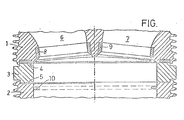
- the single figure shows an axial section through a cylinder head 1, a cylinder tube 2 and a ring 3 made of ceramic. Between the ring 3 and the cylinder head 1 there is an annular disc 4, while another ring plate 5 is shown exclusively in the left half of the section between the ring 3 and the cylinder head 2.
Landscapes
- Engineering & Computer Science (AREA)
- Chemical & Material Sciences (AREA)
- Combustion & Propulsion (AREA)
- Mechanical Engineering (AREA)
- General Engineering & Computer Science (AREA)
- Acoustics & Sound (AREA)
- Physics & Mathematics (AREA)
- Cylinder Crankcases Of Internal Combustion Engines (AREA)
- Pistons, Piston Rings, And Cylinders (AREA)
- Reciprocating Pumps (AREA)
- Forklifts And Lifting Vehicles (AREA)
- Compressor (AREA)
- Combustion Methods Of Internal-Combustion Engines (AREA)
Description
- Die Erfindung bezieht sich auf einen Zylinder für Hubkolbenmaschinen mit den im Oberbegriff des ersten Anspruchs angegebenen Merkmalen.
- Aus der DE-A 2 729 230 ist eine gattungsgemäße Brennkraftmaschine bekannt. Hierbei sind mit den Brenngasen in Kontakt gelangende Teile des Zylinders sowie des Abgaskanals mit einer zur Wärmeisolierung geeigneten Verkleidung, insbesondere Keramik, ausgekleidet. Speziell beschäftigt sich die gattungsgemäße DE-A 2 729 230 mit dem Problem, wie diese Auskleidung an den Wandungen von Kolben, Zylinder und Zylinderkopf zu befestigen seien, ohne daß die erheblichen Schwierigkeiten, die durch die unterschiedliche Wärmedehnung der einzelnen Materialien entstehen, auftreten. Hierzu wird ein nachgiebig verformbarer Haftstoff vorgeschlagen, da die Auskleidung zumindest auf einer Seite immer am Zylinderkopf- bzw. Zylindermaterial anliegt.
- Aus der DE-A 2 630 225 ist hingegen ein Zylinder bekannt, bei dem ein eingespannter Ring zwischen Zylinderkopf und Zylinderrohr aus einem Material höherer Festigkeit und/oder höherer Wärmeleitfähigkeit als der übrige Zylinder hergestellt ist. Hiermit wird die Aufgabe gelöst, eine verbesserte Wärmeableitung aus dem Zylinderkopf zu ermöglichen und die Wandtemperatur im Bereich der Höchstlage des oberen Kolbenringes abzusenken. Eine besondere Verrippung dient hierbei zur weiteren Förderung des Wärmeübergangs an die Kühlluft. Eine derart verstärkte Wärmeabfuhr im Bereich der Brennraumwandung hat auch Nachteile. Zum einen ist im Kaltstart- und Teillastbetrieb mit verstärkter Brennstoffkondensation und Flammenverlöschung an der extrem gekühlten Zylinderinnenwand und dementsprechend höherer HC-Emission zu rechnen. Zum anderen wird durch die starke Wärmeableitung der Wirkungsgrad infolge der herabgesetzten Brennraumtemperatur gesenkt.
- Der Erfindung liegt die Aufgabe zugrunde, einen im Bereich zwischen Zylinderkopf und Zylinderrohr angeordneten Keramikring derart anzuordnen, daß Spannungen zwischen dem Zylinderkopf und dem Zylinderrohr aufgrund unterschiedlicher Wärmedehnung möglichst abgebaut werden.
- Diese Aufgabe wird durch die kennzeichnenden Merkmale des ersten Anspruchs gelöst. Die durch die Zylinderkopfschrauben ausgeübten großen Kräfte wirken ausschließlich als Druckkräfte auf das Keramikteil, für deren Aufnahme der Werkstoff gut geeignet ist. Dadurch entfallen die aus der DE-A 2 729 230 bekannten Befestigungsprobleme. Die durch den Brennraumdruck verursachten Kräfte bewirken im Material eine unerwünschte Zugspannung, die sich jedoch durch die Ringform vollkommen gleichmäßig verteilt. Dabei ist '--r Ring vorzugsweise so ausgeführt, daß er nicm vom oberen Kolbenring überlaufen wird, was bereits bei sehr kleinen Fugenstufen zu Schäden führen könnte. Gleichzeitig wird damit sichergestellt, daß der obere Kolbenring im oberen Totpunkt an einem gut gekühlten Teil der Brennraumwand anliegt, so daß sich eine Überhitzung mit der Gefahr des Ölkohleansatzes vermieden wird. Darüber hinaus hat der Keramikring den Vorteil, daß der Wärmefluß vom Zylinderkopf zum Zylinderrohr unterbunden wird, so daß die unerwünschte zusätzliche Aufheizung des Zylinderrohres in seinem oberen Bereich unterbleibt.
- Radiale Spannung zwischen Zylinderkopf und wärmedämmendem Ring werden erfindungsgemäß durch eine zwischengelegte Ringscheibe, die zwei Gleitebenen für Mikroverschiebungen bildet, abgebaut, während das gleiche für Spannungen zwischen Zylinderrohr und wärmedämmendem Ring durch eine zusätzliche Ringscheibe erreicht werden kann. Als Material hierfür ist Stahlblech gut geeignet.
- Der Keramikring ist vorzugsweise mit entsprechenden Einpaßteilen einfach zwischen Zylinderkopf und Zylinderrohr eingesetzt und ganz oder teilweise dem Kühlmedium ausgesetzt. Zylinderkopf und Zylinderrohr können dabei üblicherweise miteinander verspannt oder verschraubt sein. Zur deutlichen Verringerung des Wärmeübergangs an der Außenseite ist der Ring auch bei ansonsten verripptem Zylinderrohr an seiner Außenseite glatt und zylindrisch ausgeführt.
- Im folgenden wird die Erfindung anhand eines bevorzugten, schematischen Ausführungsbeispielsnähererläutert.
- Die einzige Figur zeigt einen Axialschnitt durch einen Zylinderkopf 1, ein Zylinderrohr 2 und einen Ring 3 aus Keramik. Zwischen dem Ring 3 und dem Zylinderkopf 1 befindet sich eine Ringscheibe 4, während ausschließlich in der linken Hälfte des Schnittes zwischen dem Ring 3 und dem Zylinderkopf 2 ein weiteres Ringblech 5 gezeigt ist.
- Im Zylinderkopf 1 sind der Einlaß- 6 und Auslaßkanal 7 mit eingesetzten Ventilsitzen 8 und 9 zu erkennen. Mit 10 ist die Lage des oberen Kolbenringes im oberen Totpunkt bezeichnet.
Claims (4)
Priority Applications (1)
| Application Number | Priority Date | Filing Date | Title |
|---|---|---|---|
| AT81105586T ATE6685T1 (de) | 1980-08-23 | 1981-07-16 | Zylinder fuer hubkolbenmaschinen. |
Applications Claiming Priority (2)
| Application Number | Priority Date | Filing Date | Title |
|---|---|---|---|
| DE19803031926 DE3031926A1 (de) | 1980-08-23 | 1980-08-23 | Zylinder fuer hubkolbenmaschinen |
| DE3031926 | 1980-08-23 |
Publications (2)
| Publication Number | Publication Date |
|---|---|
| EP0046505A1 EP0046505A1 (de) | 1982-03-03 |
| EP0046505B1 true EP0046505B1 (de) | 1984-03-14 |
Family
ID=6110299
Family Applications (1)
| Application Number | Title | Priority Date | Filing Date |
|---|---|---|---|
| EP81105586A Expired EP0046505B1 (de) | 1980-08-23 | 1981-07-16 | Zylinder für Hubkolbenmaschinen |
Country Status (4)
| Country | Link |
|---|---|
| US (1) | US4462343A (de) |
| EP (1) | EP0046505B1 (de) |
| AT (1) | ATE6685T1 (de) |
| DE (2) | DE3031926A1 (de) |
Families Citing this family (6)
| Publication number | Priority date | Publication date | Assignee | Title |
|---|---|---|---|---|
| DE3236185A1 (de) * | 1982-09-30 | 1984-04-05 | Klöckner-Humboldt-Deutz AG, 5000 Köln | Hubkolbenbrennkraftmaschine |
| US4831976A (en) * | 1987-02-02 | 1989-05-23 | General Motors Corporation | Engine with valve seat inserts and method of retaining |
| US5072697A (en) * | 1991-03-13 | 1991-12-17 | Sputhe Alan C | Sealing apparatus for an internal combustion engine |
| FI106972B (fi) | 1999-06-04 | 2001-05-15 | Waertsilae Tech Oy Ab | Koksinpoistorengasjärjestely |
| CA2607138A1 (en) * | 2005-03-23 | 2006-09-28 | David M. Baker | Utility scale method and apparatus to convert low temperature thermal energy to electricity |
| US20090077961A1 (en) * | 2007-09-24 | 2009-03-26 | Baker David M | Heat Concentrator Piston and Chamber |
Family Cites Families (14)
| Publication number | Priority date | Publication date | Assignee | Title |
|---|---|---|---|---|
| DE636782C (de) * | 1936-10-14 | Michael Martinka Dipl Ing | Arbeitszylinder fuer Brennkraftmaschinen | |
| GB178827A (en) * | 1921-04-19 | 1923-05-10 | Moteurs Gnome & Rhone Soc D | Improvements in combustion chambers for internal combustion engines |
| US1814781A (en) * | 1927-05-04 | 1931-07-14 | Ass Elect Ind | Internal combustion engine |
| US1872931A (en) * | 1928-03-19 | 1932-08-23 | Doherty Res Co | Fuel supply for internal combustion engines |
| US2577022A (en) * | 1945-11-22 | 1951-12-04 | Sulzer Ag | Piston ring |
| US3081754A (en) * | 1961-02-14 | 1963-03-19 | Georges Raymond | Internal combustion engines, in particular of the constant pressure cycle type |
| DE1301655C2 (de) * | 1965-01-12 | 1970-04-23 | Daimler Benz Ag | Brennkraftmaschine mit fluessigkeitsgekuehlten Zylinderlaufbuchsen |
| US3408995A (en) * | 1967-05-22 | 1968-11-05 | Thomas A. Johnson | Combustion chamber design and material for internal combustion cylinders and engines |
| JPS5332336B2 (de) * | 1973-05-24 | 1978-09-07 | ||
| DE2630225A1 (de) * | 1976-07-06 | 1978-01-19 | Kloeckner Humboldt Deutz Ag | Rippenzylinder fuer eine luftgekuehlte hubkolbenmaschine |
| DE7621243U1 (de) * | 1976-07-06 | 1980-02-21 | Kloeckner-Humboldt-Deutz Ag, 5000 Koeln | Rippenzylinder fuer eine luftgekuehlte hubkolbenmaschine |
| DE2729230A1 (de) * | 1977-06-29 | 1979-01-11 | Daimler Benz Ag | Brennkraftmaschine |
| DE2752633A1 (de) * | 1977-11-25 | 1979-05-31 | Kloeckner Humboldt Deutz Ag | Zylinder fuer eine hubkolbenbrennkraftmaschine |
| DE2937788A1 (de) * | 1979-09-19 | 1981-04-02 | Klöckner-Humboldt-Deutz AG, 5000 Köln | Leichtmetallzylinderkopf fuer brennkraftmaschinen |
-
1980
- 1980-08-23 DE DE19803031926 patent/DE3031926A1/de not_active Withdrawn
-
1981
- 1981-07-16 DE DE8181105586T patent/DE3162657D1/de not_active Expired
- 1981-07-16 EP EP81105586A patent/EP0046505B1/de not_active Expired
- 1981-07-16 AT AT81105586T patent/ATE6685T1/de active
- 1981-08-21 US US06/294,829 patent/US4462343A/en not_active Expired - Fee Related
Also Published As
| Publication number | Publication date |
|---|---|
| DE3162657D1 (en) | 1984-04-19 |
| ATE6685T1 (de) | 1984-03-15 |
| DE3031926A1 (de) | 1982-04-01 |
| EP0046505A1 (de) | 1982-03-03 |
| US4462343A (en) | 1984-07-31 |
Similar Documents
| Publication | Publication Date | Title |
|---|---|---|
| EP0752088B1 (de) | Wärmetauscherrohr für heizkessel | |
| DE3032253C2 (de) | Verbrennungsmotor, insbesondere Dieselmotor | |
| DE112007000918B4 (de) | Zylinderkopf für einen Motor sowie Motor | |
| EP1795711A2 (de) | Abgasturbolader | |
| EP1227236A2 (de) | Kurbelgehäuse für eine flüssigkeitsgekühlte Hubkolben-Brennkraftmaschine | |
| DE2458460B2 (de) | Dichtung zum abdichten zwischen bauteilen unterschiedlicher betriebstemperatur | |
| DE4141051A1 (de) | Brennkraftmaschine mit einer dampfturbinenanlage als leistungsgekoppelter zusatzeinrichtung | |
| DE2262770C3 (de) | Ansaugsystem für eine gemischverdichtende Brennkraftmaschine | |
| EP0105108B1 (de) | Hubkolbenbrennkraftmaschine | |
| EP0046505A1 (de) | Zylinder für Hubkolbenmaschinen | |
| EP0315098A1 (de) | Wärmetauscher zur Erwärmung von Flüssigkeiten | |
| DE2332716B2 (de) | Ansaugsystem fuer eine brennkraftmaschine | |
| EP1063408B1 (de) | Zylinderkopf | |
| DE1140305B (de) | Kolbenmaschine fuer gasfoermige Medien | |
| DE1005319B (de) | Rohrgelenkverbindung fuer Auspuff- und Ansaugeleitungen von Brennkraftmaschinen | |
| DE19832844B4 (de) | Verbrennungsmotor mit einer auswechselbaren Zylinderlaufbuchse | |
| DE3521789A1 (de) | Fluessigkeitsgekuehltes zylinderrohr | |
| DE102005037383A1 (de) | Zylinderkopf für eine Brennkraftmaschine | |
| EP0999387B1 (de) | Anordnung zur Abdichtung des Brennraums bei Dieselmotoren mit einer Zylinderkopfdichtung | |
| DE748748C (de) | Zweitakt-Brennkraftmaschine | |
| EP1182344A2 (de) | Vorrichtung zur Rückführung von Gas an einem Verbrennungsmotor | |
| DE2360215B2 (de) | Ansaug- und Auspuffleitungsanordnung für eine Brennkraftmaschine | |
| AT150535B (de) | Flüssigkeitsgekühlter Zylinder, vorzugsweise für Hochleistungs-Brennkraftmaschinen. | |
| DE3150919A1 (de) | Ansaugventil | |
| DE2002785C3 (de) | Zylinderkopf für Hubkolbenbrennkraftmaschinen |
Legal Events
| Date | Code | Title | Description |
|---|---|---|---|
| PUAI | Public reference made under article 153(3) epc to a published international application that has entered the european phase |
Free format text: ORIGINAL CODE: 0009012 |
|
| 17P | Request for examination filed |
Effective date: 19811029 |
|
| AK | Designated contracting states |
Designated state(s): AT DE FR GB |
|
| GRAA | (expected) grant |
Free format text: ORIGINAL CODE: 0009210 |
|
| AK | Designated contracting states |
Designated state(s): AT DE FR GB |
|
| REF | Corresponds to: |
Ref document number: 6685 Country of ref document: AT Date of ref document: 19840315 Kind code of ref document: T |
|
| REF | Corresponds to: |
Ref document number: 3162657 Country of ref document: DE Date of ref document: 19840419 |
|
| ET | Fr: translation filed | ||
| PGFP | Annual fee paid to national office [announced via postgrant information from national office to epo] |
Ref country code: FR Payment date: 19840615 Year of fee payment: 4 |
|
| PGFP | Annual fee paid to national office [announced via postgrant information from national office to epo] |
Ref country code: DE Payment date: 19840913 Year of fee payment: 4 |
|
| PLBI | Opposition filed |
Free format text: ORIGINAL CODE: 0009260 |
|
| PLBI | Opposition filed |
Free format text: ORIGINAL CODE: 0009260 |
|
| 26 | Opposition filed |
Opponent name: MTU MOTOREN- UND TURBINEN-UNION FRIEDRICHSHAFEN GM Effective date: 19841115 |
|
| 26 | Opposition filed |
Opponent name: FELDMUEHLE AKTIENGESELLSCHAFT, DUESSELDORF Effective date: 19841212 |
|
| PGFP | Annual fee paid to national office [announced via postgrant information from national office to epo] |
Ref country code: AT Payment date: 19860609 Year of fee payment: 6 |
|
| PG25 | Lapsed in a contracting state [announced via postgrant information from national office to epo] |
Ref country code: AT Effective date: 19870716 |
|
| PG25 | Lapsed in a contracting state [announced via postgrant information from national office to epo] |
Ref country code: FR Free format text: LAPSE BECAUSE OF NON-PAYMENT OF DUE FEES Effective date: 19880331 |
|
| GBPC | Gb: european patent ceased through non-payment of renewal fee | ||
| REG | Reference to a national code |
Ref country code: FR Ref legal event code: ST |
|
| PG25 | Lapsed in a contracting state [announced via postgrant information from national office to epo] |
Ref country code: DE Effective date: 19880722 |
|
| RDAG | Patent revoked |
Free format text: ORIGINAL CODE: 0009271 |
|
| STAA | Information on the status of an ep patent application or granted ep patent |
Free format text: STATUS: PATENT REVOKED |
|
| GBPR | Gb: patent revoked under art. 102 of the ep convention designating the uk as contracting state | ||
| 27W | Patent revoked |
Effective date: 19881017 |
|
| APAH | Appeal reference modified |
Free format text: ORIGINAL CODE: EPIDOSCREFNO |