EP0044476A2 - Tube pour le chauffage indirect de matières facilement ruisselantes et échangeur de chaleur composé de tels tubes - Google Patents
Tube pour le chauffage indirect de matières facilement ruisselantes et échangeur de chaleur composé de tels tubes Download PDFInfo
- Publication number
- EP0044476A2 EP0044476A2 EP81105348A EP81105348A EP0044476A2 EP 0044476 A2 EP0044476 A2 EP 0044476A2 EP 81105348 A EP81105348 A EP 81105348A EP 81105348 A EP81105348 A EP 81105348A EP 0044476 A2 EP0044476 A2 EP 0044476A2
- Authority
- EP
- European Patent Office
- Prior art keywords
- tube
- tubes
- pipe
- heat exchanger
- section
- Prior art date
- Legal status (The legal status is an assumption and is not a legal conclusion. Google has not performed a legal analysis and makes no representation as to the accuracy of the status listed.)
- Granted
Links
Images


Classifications
-
- F—MECHANICAL ENGINEERING; LIGHTING; HEATING; WEAPONS; BLASTING
- F26—DRYING
- F26B—DRYING SOLID MATERIALS OR OBJECTS BY REMOVING LIQUID THEREFROM
- F26B3/00—Drying solid materials or objects by processes involving the application of heat
- F26B3/18—Drying solid materials or objects by processes involving the application of heat by conduction, i.e. the heat is conveyed from the heat source, e.g. gas flame, to the materials or objects to be dried by direct contact
- F26B3/22—Drying solid materials or objects by processes involving the application of heat by conduction, i.e. the heat is conveyed from the heat source, e.g. gas flame, to the materials or objects to be dried by direct contact the heat source and the materials or objects to be dried being in relative motion, e.g. of vibration
-
- F—MECHANICAL ENGINEERING; LIGHTING; HEATING; WEAPONS; BLASTING
- F26—DRYING
- F26B—DRYING SOLID MATERIALS OR OBJECTS BY REMOVING LIQUID THEREFROM
- F26B11/00—Machines or apparatus for drying solid materials or objects with movement which is non-progressive
- F26B11/02—Machines or apparatus for drying solid materials or objects with movement which is non-progressive in moving drums or other mainly-closed receptacles
- F26B11/04—Machines or apparatus for drying solid materials or objects with movement which is non-progressive in moving drums or other mainly-closed receptacles rotating about a horizontal or slightly-inclined axis
- F26B11/0404—Machines or apparatus for drying solid materials or objects with movement which is non-progressive in moving drums or other mainly-closed receptacles rotating about a horizontal or slightly-inclined axis with internal subdivision of the drum, e.g. for subdividing or recycling the material to be dried
- F26B11/0418—Machines or apparatus for drying solid materials or objects with movement which is non-progressive in moving drums or other mainly-closed receptacles rotating about a horizontal or slightly-inclined axis with internal subdivision of the drum, e.g. for subdividing or recycling the material to be dried the subdivision consisting of a plurality of parallel tubes, e.g. through which the material to be dried is conveyed in single or multi-pass fashion
- F26B11/0422—Machines or apparatus for drying solid materials or objects with movement which is non-progressive in moving drums or other mainly-closed receptacles rotating about a horizontal or slightly-inclined axis with internal subdivision of the drum, e.g. for subdividing or recycling the material to be dried the subdivision consisting of a plurality of parallel tubes, e.g. through which the material to be dried is conveyed in single or multi-pass fashion the tubes having internal members
-
- F—MECHANICAL ENGINEERING; LIGHTING; HEATING; WEAPONS; BLASTING
- F28—HEAT EXCHANGE IN GENERAL
- F28D—HEAT-EXCHANGE APPARATUS, NOT PROVIDED FOR IN ANOTHER SUBCLASS, IN WHICH THE HEAT-EXCHANGE MEDIA DO NOT COME INTO DIRECT CONTACT
- F28D11/00—Heat-exchange apparatus employing moving conduits
- F28D11/02—Heat-exchange apparatus employing moving conduits the movement being rotary, e.g. performed by a drum or roller
- F28D11/04—Heat-exchange apparatus employing moving conduits the movement being rotary, e.g. performed by a drum or roller performed by a tube or a bundle of tubes
-
- F—MECHANICAL ENGINEERING; LIGHTING; HEATING; WEAPONS; BLASTING
- F28—HEAT EXCHANGE IN GENERAL
- F28F—DETAILS OF HEAT-EXCHANGE AND HEAT-TRANSFER APPARATUS, OF GENERAL APPLICATION
- F28F1/00—Tubular elements; Assemblies of tubular elements
- F28F1/02—Tubular elements of cross-section which is non-circular
Definitions
- the invention relates to a tube for indirect heat treatment of powdery to granular, free-flowing material which is parallel to the tube,. Rotatable about an axis that can be inside or outside the tube, and a heat exchanger that is constructed from such tubes and components for manufacturing the tube bundle for such a heat exchanger.
- the rotary kiln can be divided into parallel chambers to increase the surface.
- a continuous process is preferred; therefore are in known rotary kilns Conveying elements available for the product to be treated; Usually, these are the helix in the (cylindrical) tube on the inside. It is known that it is very important that the material to be treated is thoroughly mixed in the tube in order to achieve uniform treatment and good heat transfer and to avoid damage to the material. Therefore, in known heat exchangers to improve the mixing effect, in addition to the helical conveying elements, baffles or rods or other baffles are also provided parallel to the tube jacket, as a result of which better mixing is achieved when the tube is turned.
- a tube or a heat exchanger which consists of a plurality of tubes connected in parallel has advantageous properties if the tube jacket is composed of flat surfaces and baffles are present at least on an inner tube jacket surface at an angle to the tube axis.
- the invention therefore relates to a tube for indirect heat treatment of powdery to granular, free-flowing material which runs parallel to the tube about an axis which can be inside or outside the tube, is rotatable and the tubular jacket is composed of flat surfaces and baffles are provided at least on an inner tubular jacket surface at an angle to the pipe axis. Pipes whose cross sections are square or equilateral triangular are very particularly preferred.
- a heat exchanger constructed from the tubes according to the invention is particularly suitable for heat exchange with another solid medium if equilateral triangles or squares are interconnected in the densest packing, which are flowed through in such a way that two tubes through which the same medium flows do not abut one side.
- a line-shaped arrangement of the tubes according to the invention can be useful. The distance between two such tube surface bundles can be chosen freely according to the heat transfer conditions.
- the invention is also directed to the internals for the heat exchanger, by means of which the tube bundles with flat tube jacket surfaces can be produced in a simple manner. They are formed from sheets that are folded in such a way that by connecting two identical or different sheets on their two outer sides, a row of tubes with flat tube jacket surfaces is created.
- the pipe according to the invention with flat surfaces has several advantages over the known cylindrical pipe, which are particularly useful when several such pipes are connected in parallel. With the same cross-section, the heat exchange surface is larger. With less effort than with cylindrical pipes, the conveying and mixing performance can be improved by simple installations. While with a circular tube for manufacturing reasons, a spiral running around the entire inner wall is practically always required and to increase the mixing effect, baffles on the wall are required, with a triangular or quadrangular pipe, it is sufficient if sheets are attached to a pipe inner wall at an angle to the axis. The dwell time spectrum is not significantly broadened by omitting conveyor elements on some inner sides. Because of the conveying elements, the rotary kiln according to the invention is generally operated horizontally.
- Solid material can also flow through it in cocurrent or countercurrent without difficulty.
- it is considerably less complex if rectangular guide plates only have to be attached to a flat inner wall than if a continuous helix has to be attached to the inner tube.
- Such tubes can also be produced with a very small cross section without difficulty.
- the heat exchange surface can thereby be considerably increased for a given cross section of the furnace; in addition, the mixing compared to round pipes is increased.
- the edges where the flat outer surfaces meet look like chicanes. It has been shown that rods or other baffles can usually be dispensed with in the tubes according to the invention. Despite the unusual tube shape, a reactor can be produced more economically from the tubes according to the invention than with round tubes of the same output.
- heat exchanger there are no problems with the dimensioning of the heat exchanger; however, some conditions for optimal heat transfer are particularly good customizable.
- a heat exchanger can be adapted particularly well both for indirect heat exchange with a gas or a liquid or with another solid substance.
- the triangular and rectangular cross section of the tubes is preferred.
- the obvious hexagonal honeycomb arrangement in a heat exchanger is less suitable. Even pipes with a side length of a few centimeters can be realized.
- the shape of the tubes according to the invention allows a particularly simple manufacture of the heat exchanger inserts.
- a tube 1 according to the invention is shown schematically with a square cross section.
- the pipe is horizontal, it is sufficient to transport the solid if rectangular conveyor ribs 2 are welded onto an inside.
- baffles parallel to the pipe axis can normally be dispensed with.
- a square tube 1 with conveyor 2 and baffle ribs 3 is shown in cross and longitudinal section.
- FIG. 4 shows a triangular tube 4 with conveying ribs 5 and retaining ribs 6.
- the length of the flat surfaces in cross section is particularly preferably 80 to 200 mm.
- the tubes according to the invention are connected in parallel in order to enlarge the heat exchange surface.
- a longitudinal section through such a heat exchanger is shown in Fig. 5.
- the interconnected pipes 10 are normally surrounded by a cylindrical sleeve 11.
- the reactor is operated horizontally.
- a heat exchange is to take place between two solid products.
- the heat-emitting product is fed in via the hopper 12 and passes through the reactor from left to right. A mirror image of this is on the on the right side (not shown here) there is an analog feeding device for the cold product; during the passage through the tubes 10 from right to left, it absorbs heat and exits the heat exchanger via the outlet opening 13.
- the product feed device 14 effects a uniform metering.
- the metering 14 always ensures that the fill level in the tubes 10 always remains constant over the entire length, and that all tubes which are flowed through by the same product are filled equally, if at all A correction of the quantity may be necessary for the outer tubes of the insert, since these tubes are not equally involved in heat transfer on all sides.
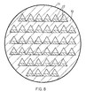
- a section 7-7 through the heat exchanger in Fig. 5 with triangular tubes is shown in Fig. 6, with square tubes in Fig. 7.
- the tubes 10a are flowed through in the opposite direction by the product to be heated, the tubes 10b by the product to be cooled.
- the tubes 12 are combined like a band in this case; the solid medium is guided through them.
- the heating or cooling gas or the liquid flows around them on all sides.
- the densest packing was omitted here in order to reduce the flow velocity e.g. of the gas.
- This structure is particularly preferred when the solid substance flowing through an insert according to FIG. 10 is to give off or absorb its heat to a liquid or a gas, for which of course no tubular guide is necessary.
- a liquid medium the gap between two inserts according to FIG. 10 can be small. If it is in the second medium is a gas, it may be useful if g to the disk inserts by Fi. 10 outside fins are present to increase the heat exchange area.
- these pipes can achieve heat transfer coefficients of over 100 Wm -2 K -1 based on the entire pipe area.
Landscapes
- Engineering & Computer Science (AREA)
- Mechanical Engineering (AREA)
- General Engineering & Computer Science (AREA)
- Physics & Mathematics (AREA)
- Life Sciences & Earth Sciences (AREA)
- Thermal Sciences (AREA)
- Microbiology (AREA)
- Geometry (AREA)
- Sustainable Development (AREA)
- Heat-Exchange Devices With Radiators And Conduit Assemblies (AREA)
Applications Claiming Priority (2)
| Application Number | Priority Date | Filing Date | Title |
|---|---|---|---|
| DE3027187 | 1980-07-18 | ||
| DE19803027187 DE3027187A1 (de) | 1980-07-18 | 1980-07-18 | Rohr zur indirekten waermebehandlung von rieselfaehigen stoffen, aus solchen rohren zusammengesetzter waermeaustauscher und bauteile zur fertigung der rohrbuendel |
Publications (3)
| Publication Number | Publication Date |
|---|---|
| EP0044476A2 true EP0044476A2 (fr) | 1982-01-27 |
| EP0044476A3 EP0044476A3 (en) | 1982-09-22 |
| EP0044476B1 EP0044476B1 (fr) | 1985-05-22 |
Family
ID=6107476
Family Applications (1)
| Application Number | Title | Priority Date | Filing Date |
|---|---|---|---|
| EP81105348A Expired EP0044476B1 (fr) | 1980-07-18 | 1981-07-09 | Tube pour le chauffage indirect de matières facilement ruisselantes et échangeur de chaleur composé de tels tubes |
Country Status (3)
| Country | Link |
|---|---|
| EP (1) | EP0044476B1 (fr) |
| DE (2) | DE3027187A1 (fr) |
| ES (1) | ES8206011A1 (fr) |
Cited By (3)
| Publication number | Priority date | Publication date | Assignee | Title |
|---|---|---|---|---|
| EP0370144A1 (fr) * | 1987-09-03 | 1990-05-30 | Kawasaki Jukogyo Kabushiki Kaisha | Procédé de régulation de l'humidité du charbon |
| EP2348272A3 (fr) * | 2010-01-22 | 2015-08-26 | Technische Universität Darmstadt | Echangeur thermique régénératif et procédé de transmission de chaleur entre deux matières solides |
| CN115388625A (zh) * | 2022-08-30 | 2022-11-25 | 湖南越洋药业有限公司 | 一种应用于甲泼尼龙生产的反冲旋转式烘干设备 |
Families Citing this family (1)
| Publication number | Priority date | Publication date | Assignee | Title |
|---|---|---|---|---|
| CN115388624B (zh) * | 2022-08-30 | 2023-06-13 | 湖南越洋药业有限公司 | 一种应用于甲泼尼龙生产的旋转可调式烘干设备 |
Citations (8)
| Publication number | Priority date | Publication date | Assignee | Title |
|---|---|---|---|---|
| FR489266A (fr) * | 1918-03-12 | 1919-01-11 | Gio Ansaldo & Cie | Faisceau tubulaire réfrigérant avec circulation d'un liquide à l'extérieur et d'un fluide à l'intérieur |
| GB252373A (en) * | 1925-05-19 | 1927-04-14 | Simmon Maschf Hans | Process and apparatus for the exchange of heat between gaseous, vapour like or liquid bodies |
| US1769412A (en) * | 1928-06-09 | 1930-07-01 | Traylor Engineering & Mfg Co | Rotary tube cooler |
| US2899176A (en) * | 1959-08-11 | Heat exchanger | ||
| US3602298A (en) * | 1969-04-25 | 1971-08-31 | Mecislaus Joseph Ciesielski | Heat exchanger |
| DE1778226A1 (de) * | 1968-04-09 | 1971-10-14 | Ljungberg Bror Gustaf | Rauch-oder Flammenrohr,insbesondere fuer Heizkessel |
| DE2109308A1 (de) * | 1971-02-26 | 1972-09-07 | Linde Ag | Verfahren zur Herstellung eines Blechpaketes, insbesondere eines Platten Wärmetauschers |
| DE2946904B1 (de) * | 1979-11-21 | 1981-02-26 | Bayer Ag, 5090 Leverkusen | Von außen beheiz- oder kühlbares, drehbares Wärmetauscherrohr zum Wärmebehandeln von pulvrigem bis körnigem, rieselfähigem, ggf. angeschlämmtem Gut |
-
1980
- 1980-07-18 DE DE19803027187 patent/DE3027187A1/de not_active Withdrawn
-
1981
- 1981-07-09 EP EP81105348A patent/EP0044476B1/fr not_active Expired
- 1981-07-09 DE DE8181105348T patent/DE3170594D1/de not_active Expired
- 1981-07-17 ES ES504077A patent/ES8206011A1/es not_active Expired
Patent Citations (8)
| Publication number | Priority date | Publication date | Assignee | Title |
|---|---|---|---|---|
| US2899176A (en) * | 1959-08-11 | Heat exchanger | ||
| FR489266A (fr) * | 1918-03-12 | 1919-01-11 | Gio Ansaldo & Cie | Faisceau tubulaire réfrigérant avec circulation d'un liquide à l'extérieur et d'un fluide à l'intérieur |
| GB252373A (en) * | 1925-05-19 | 1927-04-14 | Simmon Maschf Hans | Process and apparatus for the exchange of heat between gaseous, vapour like or liquid bodies |
| US1769412A (en) * | 1928-06-09 | 1930-07-01 | Traylor Engineering & Mfg Co | Rotary tube cooler |
| DE1778226A1 (de) * | 1968-04-09 | 1971-10-14 | Ljungberg Bror Gustaf | Rauch-oder Flammenrohr,insbesondere fuer Heizkessel |
| US3602298A (en) * | 1969-04-25 | 1971-08-31 | Mecislaus Joseph Ciesielski | Heat exchanger |
| DE2109308A1 (de) * | 1971-02-26 | 1972-09-07 | Linde Ag | Verfahren zur Herstellung eines Blechpaketes, insbesondere eines Platten Wärmetauschers |
| DE2946904B1 (de) * | 1979-11-21 | 1981-02-26 | Bayer Ag, 5090 Leverkusen | Von außen beheiz- oder kühlbares, drehbares Wärmetauscherrohr zum Wärmebehandeln von pulvrigem bis körnigem, rieselfähigem, ggf. angeschlämmtem Gut |
Cited By (4)
| Publication number | Priority date | Publication date | Assignee | Title |
|---|---|---|---|---|
| EP0370144A1 (fr) * | 1987-09-03 | 1990-05-30 | Kawasaki Jukogyo Kabushiki Kaisha | Procédé de régulation de l'humidité du charbon |
| EP2348272A3 (fr) * | 2010-01-22 | 2015-08-26 | Technische Universität Darmstadt | Echangeur thermique régénératif et procédé de transmission de chaleur entre deux matières solides |
| CN115388625A (zh) * | 2022-08-30 | 2022-11-25 | 湖南越洋药业有限公司 | 一种应用于甲泼尼龙生产的反冲旋转式烘干设备 |
| CN115388625B (zh) * | 2022-08-30 | 2023-06-13 | 湖南越洋药业有限公司 | 一种应用于甲泼尼龙生产的反冲旋转式烘干设备 |
Also Published As
| Publication number | Publication date |
|---|---|
| DE3170594D1 (en) | 1985-06-27 |
| ES504077A0 (es) | 1982-06-16 |
| EP0044476B1 (fr) | 1985-05-22 |
| EP0044476A3 (en) | 1982-09-22 |
| ES8206011A1 (es) | 1982-06-16 |
| DE3027187A1 (de) | 1982-02-11 |
Similar Documents
| Publication | Publication Date | Title |
|---|---|---|
| DE2124010C3 (de) | Wärmeaustauscher zum Erhitzen, Trocknen oder Abkühlen | |
| DE2544916B2 (de) | Vorrichtung zum Kühlen von Lebensmitteln | |
| EP0144092A2 (fr) | Machine pour mélanger et pétrir | |
| DE2232386B2 (de) | Vorrichtung zur Kältetrocknung von Gas, insbesondere Luft | |
| DE3136589A1 (de) | Temperierbarer statischer mischer und reaktor | |
| DE2804106C2 (de) | Wärmetauscher | |
| DE2951352C2 (de) | Flachrohr-Wärmetauscher | |
| EP0019244B1 (fr) | Dispositif et procédé pour la pyrolyse de déchets | |
| DE2100248C3 (de) | Einrichtung zur Wärme-, Kälte,- und/oder Stoffbehandlung körnigen, rieselfähigen Gutes | |
| DE2048226B2 (de) | Drehrohrofen zur Gewinnung von Fluorwasserstoffsäure | |
| EP2976589A1 (fr) | Récupérateur à faisceaux de tubes sur un four de frittage, et procédé de transfert de chaleur au moyen d'un four de frittage et d'un récupérateur à faisceaux de tubes | |
| DE2256711A1 (de) | Kuehlverfahren und -vorrichtung | |
| DE2853054B2 (de) | Vorrichtung zum Auspressen von fließfähigen Massen | |
| EP0044476B1 (fr) | Tube pour le chauffage indirect de matières facilement ruisselantes et échangeur de chaleur composé de tels tubes | |
| DE19849099C2 (de) | Vorrichtung zum kontinuierlichen Temperieren von zu verarbeitenden kakaobutterhaltigen oder ähnlichen fetthaltigen Massen | |
| DE2550035C3 (de) | Wärmetauscher mit einer Vielzahl mit Abstand voneinander angeordneter Wärmetauschmedium-Strömungsrohre | |
| DE2946904C2 (de) | Von außen beheiz- oder kühlbares, drehbares Wärmetauscherrohr zum Wärmebehandeln von pulvrigem bis körnigem, rieselfähigem, ggf. angeschlämmtem Gut | |
| DE1298083B (de) | Schneckenmaschine | |
| DE1567297C3 (de) | Vorrichtung zum Temperieren einer Zuckerfüllmasse | |
| DE2164012C2 (de) | Verfahren und Drehtrommel zur Gegenstrombehandlung von fließfähigen Feststoffen mit einer fließenden Flüssigkeit | |
| EP0004081B1 (fr) | Refroidisseur à cuve | |
| DE2349305C3 (de) | Vorrichtung zum Durchführen eines physikalisch-chemischen Austauschvorgangs | |
| DE1542151C3 (de) | Wischer für Dünnschichtreaktions- oder -verdampf errohr | |
| DE102005045051A1 (de) | Drehrohrofen | |
| DE3407104A1 (de) | Desublimator |
Legal Events
| Date | Code | Title | Description |
|---|---|---|---|
| PUAI | Public reference made under article 153(3) epc to a published international application that has entered the european phase |
Free format text: ORIGINAL CODE: 0009012 |
|
| 17P | Request for examination filed |
Effective date: 19810709 |
|
| AK | Designated contracting states |
Designated state(s): BE CH DE FR GB IT LI NL |
|
| KL | Correction list |
Free format text: 82/03 TITELBLATT |
|
| PUAL | Search report despatched |
Free format text: ORIGINAL CODE: 0009013 |
|
| AK | Designated contracting states |
Designated state(s): BE CH DE FR GB IT LI NL |
|
| RAP1 | Party data changed (applicant data changed or rights of an application transferred) |
Owner name: KELLER, WOLFGANG |
|
| GRAA | (expected) grant |
Free format text: ORIGINAL CODE: 0009210 |
|
| AK | Designated contracting states |
Designated state(s): BE CH DE FR GB IT LI NL |
|
| PG25 | Lapsed in a contracting state [announced via postgrant information from national office to epo] |
Ref country code: NL Effective date: 19850522 Ref country code: IT Free format text: LAPSE BECAUSE OF FAILURE TO SUBMIT A TRANSLATION OF THE DESCRIPTION OR TO PAY THE FEE WITHIN THE PRESCRIBED TIME-LIMIT;WARNING: LAPSES OF ITALIAN PATENTS WITH EFFECTIVE DATE BEFORE 2007 MAY HAVE OCCURRED AT ANY TIME BEFORE 2007. THE CORRECT EFFECTIVE DATE MAY BE DIFFERENT FROM THE ONE RECORDED. Effective date: 19850522 Ref country code: FR Free format text: THE PATENT HAS BEEN ANNULLED BY A DECISION OF A NATIONAL AUTHORITY Effective date: 19850522 Ref country code: BE Effective date: 19850522 |
|
| REF | Corresponds to: |
Ref document number: 3170594 Country of ref document: DE Date of ref document: 19850627 |
|
| PG25 | Lapsed in a contracting state [announced via postgrant information from national office to epo] |
Ref country code: LI Effective date: 19850731 Ref country code: CH Effective date: 19850731 |
|
| NLV1 | Nl: lapsed or annulled due to failure to fulfill the requirements of art. 29p and 29m of the patents act | ||
| EN | Fr: translation not filed | ||
| GBPC | Gb: european patent ceased through non-payment of renewal fee | ||
| REG | Reference to a national code |
Ref country code: CH Ref legal event code: PL |
|
| PLBE | No opposition filed within time limit |
Free format text: ORIGINAL CODE: 0009261 |
|
| STAA | Information on the status of an ep patent application or granted ep patent |
Free format text: STATUS: NO OPPOSITION FILED WITHIN TIME LIMIT |
|
| 26N | No opposition filed | ||
| PG25 | Lapsed in a contracting state [announced via postgrant information from national office to epo] |
Ref country code: GB Free format text: LAPSE BECAUSE OF NON-PAYMENT OF DUE FEES Effective date: 19881118 |
|
| PGFP | Annual fee paid to national office [announced via postgrant information from national office to epo] |
Ref country code: DE Payment date: 19911021 Year of fee payment: 11 |
|
| PG25 | Lapsed in a contracting state [announced via postgrant information from national office to epo] |
Ref country code: DE Effective date: 19930401 |