EP0044476A2 - Tube for the indirect heating of easy flowing material and heat exchanger composed of such tubes - Google Patents
Tube for the indirect heating of easy flowing material and heat exchanger composed of such tubes Download PDFInfo
- Publication number
- EP0044476A2 EP0044476A2 EP81105348A EP81105348A EP0044476A2 EP 0044476 A2 EP0044476 A2 EP 0044476A2 EP 81105348 A EP81105348 A EP 81105348A EP 81105348 A EP81105348 A EP 81105348A EP 0044476 A2 EP0044476 A2 EP 0044476A2
- Authority
- EP
- European Patent Office
- Prior art keywords
- tube
- tubes
- pipe
- heat exchanger
- section
- Prior art date
- Legal status (The legal status is an assumption and is not a legal conclusion. Google has not performed a legal analysis and makes no representation as to the accuracy of the status listed.)
- Granted
Links
Images


Classifications
-
- F—MECHANICAL ENGINEERING; LIGHTING; HEATING; WEAPONS; BLASTING
- F26—DRYING
- F26B—DRYING SOLID MATERIALS OR OBJECTS BY REMOVING LIQUID THEREFROM
- F26B3/00—Drying solid materials or objects by processes involving the application of heat
- F26B3/18—Drying solid materials or objects by processes involving the application of heat by conduction, i.e. the heat is conveyed from the heat source, e.g. gas flame, to the materials or objects to be dried by direct contact
- F26B3/22—Drying solid materials or objects by processes involving the application of heat by conduction, i.e. the heat is conveyed from the heat source, e.g. gas flame, to the materials or objects to be dried by direct contact the heat source and the materials or objects to be dried being in relative motion, e.g. of vibration
-
- F—MECHANICAL ENGINEERING; LIGHTING; HEATING; WEAPONS; BLASTING
- F26—DRYING
- F26B—DRYING SOLID MATERIALS OR OBJECTS BY REMOVING LIQUID THEREFROM
- F26B11/00—Machines or apparatus for drying solid materials or objects with movement which is non-progressive
- F26B11/02—Machines or apparatus for drying solid materials or objects with movement which is non-progressive in moving drums or other mainly-closed receptacles
- F26B11/04—Machines or apparatus for drying solid materials or objects with movement which is non-progressive in moving drums or other mainly-closed receptacles rotating about a horizontal or slightly-inclined axis
- F26B11/0404—Machines or apparatus for drying solid materials or objects with movement which is non-progressive in moving drums or other mainly-closed receptacles rotating about a horizontal or slightly-inclined axis with internal subdivision of the drum, e.g. for subdividing or recycling the material to be dried
- F26B11/0418—Machines or apparatus for drying solid materials or objects with movement which is non-progressive in moving drums or other mainly-closed receptacles rotating about a horizontal or slightly-inclined axis with internal subdivision of the drum, e.g. for subdividing or recycling the material to be dried the subdivision consisting of a plurality of parallel tubes, e.g. through which the material to be dried is conveyed in single or multi-pass fashion
- F26B11/0422—Machines or apparatus for drying solid materials or objects with movement which is non-progressive in moving drums or other mainly-closed receptacles rotating about a horizontal or slightly-inclined axis with internal subdivision of the drum, e.g. for subdividing or recycling the material to be dried the subdivision consisting of a plurality of parallel tubes, e.g. through which the material to be dried is conveyed in single or multi-pass fashion the tubes having internal members
-
- F—MECHANICAL ENGINEERING; LIGHTING; HEATING; WEAPONS; BLASTING
- F28—HEAT EXCHANGE IN GENERAL
- F28D—HEAT-EXCHANGE APPARATUS, NOT PROVIDED FOR IN ANOTHER SUBCLASS, IN WHICH THE HEAT-EXCHANGE MEDIA DO NOT COME INTO DIRECT CONTACT
- F28D11/00—Heat-exchange apparatus employing moving conduits
- F28D11/02—Heat-exchange apparatus employing moving conduits the movement being rotary, e.g. performed by a drum or roller
- F28D11/04—Heat-exchange apparatus employing moving conduits the movement being rotary, e.g. performed by a drum or roller performed by a tube or a bundle of tubes
-
- F—MECHANICAL ENGINEERING; LIGHTING; HEATING; WEAPONS; BLASTING
- F28—HEAT EXCHANGE IN GENERAL
- F28F—DETAILS OF HEAT-EXCHANGE AND HEAT-TRANSFER APPARATUS, OF GENERAL APPLICATION
- F28F1/00—Tubular elements; Assemblies of tubular elements
- F28F1/02—Tubular elements of cross-section which is non-circular
Landscapes
- Engineering & Computer Science (AREA)
- Mechanical Engineering (AREA)
- General Engineering & Computer Science (AREA)
- Physics & Mathematics (AREA)
- Life Sciences & Earth Sciences (AREA)
- Thermal Sciences (AREA)
- Sustainable Development (AREA)
- Microbiology (AREA)
- Geometry (AREA)
- Heat-Exchange Devices With Radiators And Conduit Assemblies (AREA)
Abstract
Description
Die Erfindung betrifft ein Rohr zur indirekten Wärmebehandlung von pulvrigem bis körnigem, rieselfähigem Gut, das um eine Achse, die inner- oder außerhalb des Rohres liegen kann, parallel zum Rohr verlaufend,.drehbar ist, und einen Wärmetauscher, der aus solchen Rohren aufgebaut ist und Bauteilen zur Fertigung des Rohrbündels für einen solchen Wärmeaustauscher.The invention relates to a tube for indirect heat treatment of powdery to granular, free-flowing material which is parallel to the tube,. Rotatable about an axis that can be inside or outside the tube, and a heat exchanger that is constructed from such tubes and components for manufacturing the tube bundle for such a heat exchanger.
Es ist bekannt, pulvriges bis körniges, rieselfähiges Gut in einem Drehrohrofen, dessen Achse horizontal oder schräg verlaufen kann, wärmezubehandeln. Dabei kann es zu einem direkten oder indirekten Wäremübergang kommen. Ein indirekter Wärmeübergang liegt dann vor, wenn der Übergang von dem zu behandelnden Feststoff auf ein flüssiges oder gasförmiges Medium oder einen anderen Feststoff über eine Trennwand hin erfolgt, also eine direkte Berührung mit dem zu behandelnden Stoff durch das Wärmeübertragungsmedium vermieden wird.It is known to heat-treat powdery to granular, free-flowing material in a rotary kiln, the axis of which can run horizontally or at an angle. This can lead to direct or indirect heat transfer. Indirect heat transfer occurs when the transition from the solid to be treated to a liquid or gaseous medium or another solid takes place via a partition, ie direct contact with the substance to be treated by the heat transfer medium is avoided.
Der Drehrohrofen kann zur Vergrößerung der Oberfläche in parallel geschaltete Kammern unterteilt sein. Ein kontinuierlicher Verfahrensablauf ist bevorzugt; daher sind in bekannten Drehrohröfen Förderelemente für das zu behandelnde Produkt vorhanden; üblicherweise sind das im (zylindrischen) Rohr an der Innenseite anliegende Wendel. Man weiß, daß es sehr wesentlich ist, daß das zu behandelnde Gut im Rohr gut durchmischt wird, um eine gleichmäßige Behandlung und einen guten Wärmeübergang zu erreichen und um eine Schädigung des Gutes zu vermeiden. Daher sind bei bekannten Wärmetauschern zur Verbesserung der Mischwirkung zusätzlich zu den wendelförmigen Förderelementen noch parallel zum Rohrmantel Leitbleche oder Stangen oder andere Schikanen vorhanden, wodurch beim Drehen des Rohres eine bessere Vermischung erreicht wird.The rotary kiln can be divided into parallel chambers to increase the surface. A continuous process is preferred; therefore are in known rotary kilns Conveying elements available for the product to be treated; Usually, these are the helix in the (cylindrical) tube on the inside. It is known that it is very important that the material to be treated is thoroughly mixed in the tube in order to achieve uniform treatment and good heat transfer and to avoid damage to the material. Therefore, in known heat exchangers to improve the mixing effect, in addition to the helical conveying elements, baffles or rods or other baffles are also provided parallel to the tube jacket, as a result of which better mixing is achieved when the tube is turned.
Es ist auch bekannt, daß die Wärmeaustauschfläche eines Apparats dadurch vergrößert wird, daß statt eines Einzelrohres mit einem großen Querschnitt mehrere kleinere Rohre zu einem Bündel parallel geschaltet sind; auch bei einem solchen rotierenden Bündel wird von einem Drehrohrofen gesprochen.It is also known that the heat exchange surface of an apparatus is increased in that instead of a single tube with a large cross section, several smaller tubes are connected in parallel to form a bundle; Such a rotating bundle is also referred to as a rotary kiln.
Es wurde nun gefunden, daß ein Rohr oder ein Wärmeaustauscher der aus mehreren parallel geschalteten Rohren besteht, vorteilhafte Eigenschaften aufweist, wenn der Rohrmantel aus ebenen Flächen zusammengesetzt ist und schräg zur Rohrachse mindestens auf einer inneren Rohrmantelfläche Leitbleche vorhanden sind. Gegenstand der Erfindung ist daher ein Rohr zur indirekten Wärmebehandlung von pulvrigem bis körnigem, rieselfähigem Gut, das um eine Achse, die inner- oder außerhalb des Rohres liegen kann, parallel zum Rohr verlaufend, drehbar ist und dessen Rohrmantel aus ebenen Flächen zusammengesetzt ist und schräg zur Rohrachse mindestens auf einer inneren Rohrmantelfläche Leitbleche vorhanden sind. Ganz besonders bevorzugt sind Rohre, deren Querschnitte quadratisch oder gleichseitig dreieckig sind. Ein aus den erfindungsgemäßen Rohren aufgebauter Wärmeaustauscher ist für den Wärmeaustausch mit einem anderen Festmedium besonders geeignet, wenn in dichtester Packung gleichseitige Dreiecke oder Quadrate zusammengeschaltet sind, die so durchströmt werden, daß nicht zwei vom gleichen Medium durchströmte Rohre mit einer Seite aneinander stoßen. Bei einem Wärmeübergang auf ein flüssiges oder gasförmiges Medium kann eine zeilenförmige Anordnung der erfindungsgemäßen Rohre sinnvoll sein. Der Abstand zwischen zwei solchen Rohrflächenbündeln kann entsprechend den Wärmeübertragungsbedingungen frei gewählt werden. Die Erfindung richtet sich auch auf die Einbauten für die Wärmeaustauscher, durch die die Rohrbündel mit ebenen Rohrmantelflächen in einfacher Weise erzeugt werden können. Sie werden gebildet aus Blechen, die so gefaltet sind, daß durch Verbindung zweier gleicher oder ungleicher Bleche an ihren beiden Außenseiten eine Reihe von Rohren mit ebenen Rohrmantelflächen entsteht.It has now been found that a tube or a heat exchanger which consists of a plurality of tubes connected in parallel has advantageous properties if the tube jacket is composed of flat surfaces and baffles are present at least on an inner tube jacket surface at an angle to the tube axis. The invention therefore relates to a tube for indirect heat treatment of powdery to granular, free-flowing material which runs parallel to the tube about an axis which can be inside or outside the tube, is rotatable and the tubular jacket is composed of flat surfaces and baffles are provided at least on an inner tubular jacket surface at an angle to the pipe axis. Pipes whose cross sections are square or equilateral triangular are very particularly preferred. A heat exchanger constructed from the tubes according to the invention is particularly suitable for heat exchange with another solid medium if equilateral triangles or squares are interconnected in the densest packing, which are flowed through in such a way that two tubes through which the same medium flows do not abut one side. In the case of heat transfer to a liquid or gaseous medium, a line-shaped arrangement of the tubes according to the invention can be useful. The distance between two such tube surface bundles can be chosen freely according to the heat transfer conditions. The invention is also directed to the internals for the heat exchanger, by means of which the tube bundles with flat tube jacket surfaces can be produced in a simple manner. They are formed from sheets that are folded in such a way that by connecting two identical or different sheets on their two outer sides, a row of tubes with flat tube jacket surfaces is created.
Das erfindungsgemäße Rohr mit ebenen Flächen hat gegenüber dem bekannten zylindrischen Rohr einige Vorteile, die besonders zum Tragen kommen, wenn mehrere solcher Rohre parallel geschaltet sind. Bei gleichem Querschnitt ist die Wärmeaustauschfläche größer. Bei geringerem Aufwand als bei zylindrischen Rohren kann die Förder- und Mischleistung durch einfache Einbauten verbessert werden. Während bei einem kreisförmigen Rohr aus herstellungstechnischen Gründen praktisch immer eine an der ganzen Innenwand umlaufende Wendel erforderlich ist und zur Erhöhung der Mischwirkung Schikanen an der Wand erforderlich sind, reicht es bei einem drei- oder viereckigen Rohr aus, wenn an einer Rohrinnenwand schräg zur Achse verlaufend Bleche angebracht sind. Das Verweilzeitspektrum wird durch das Weglassen von Förderelementen auf einigen Innenseiten nicht wesentlich verbreitert. Wegen der Förderelemente wird der erfindungsgemäße Drehrohrofen in der Regel waagerecht betrieben. Er kann ohne Schwierigkeiten im Gleich- oder Gegenstrom auch von festem Gut durchströmt werden. Fertigungstechnisch ist es erheblich weniger aufwendig, wenn nur auf einer ebenen Innenwand rechteckige Leitbleche angebracht werden müssen, als wenn eine durchgehende Wendel am Innenrohr befestigt werden muß. Solche Rohre können auch ohne Schwierigkeiten mit einem sehr kleinen Querschnitt hergestellt werden. Die Wärmeaustauschfläche kann bei gegebenem Querschnitt des Ofens dadurch beträchlich erhöht werden; außerdem wird noch die Durchmischung gegenüber runden Rohren erhöht. Die Kanten, wo die ebenen Mantelflächen zusammenstoßen, wirken wie Schikanen. Es hat sich gezeigt, daß bei den erfindungsgemäßen Rohren auf Stäbe oder weitere Leitbleche meistens verzichtet werden kann. Trotz der unüblichen Rohrform läßt sich ein Reaktor aus den erfindungsgemäßen Rohren wirtschaftlicher als mit runden Rohren gleicher Leistung herstellen.The pipe according to the invention with flat surfaces has several advantages over the known cylindrical pipe, which are particularly useful when several such pipes are connected in parallel. With the same cross-section, the heat exchange surface is larger. With less effort than with cylindrical pipes, the conveying and mixing performance can be improved by simple installations. While with a circular tube for manufacturing reasons, a spiral running around the entire inner wall is practically always required and to increase the mixing effect, baffles on the wall are required, with a triangular or quadrangular pipe, it is sufficient if sheets are attached to a pipe inner wall at an angle to the axis. The dwell time spectrum is not significantly broadened by omitting conveyor elements on some inner sides. Because of the conveying elements, the rotary kiln according to the invention is generally operated horizontally. Solid material can also flow through it in cocurrent or countercurrent without difficulty. In terms of production technology, it is considerably less complex if rectangular guide plates only have to be attached to a flat inner wall than if a continuous helix has to be attached to the inner tube. Such tubes can also be produced with a very small cross section without difficulty. The heat exchange surface can thereby be considerably increased for a given cross section of the furnace; in addition, the mixing compared to round pipes is increased. The edges where the flat outer surfaces meet look like chicanes. It has been shown that rods or other baffles can usually be dispensed with in the tubes according to the invention. Despite the unusual tube shape, a reactor can be produced more economically from the tubes according to the invention than with round tubes of the same output.
Bei der Dimensionierung des Wärmeaustauschers treten keine Probleme auf; einige Bedingungen für einen optimalen Wärmeübergang sind jedoch besonders gut anpaßbar. Ein solcher Wärmeaustauscher läßt sich sowohl für einen indirekten Wärmeaustausch mit einem Gas oder einer Flüssigkeit oder auch mit einem anderen festen Stoff besonders gut anpassen. Der dreieckige und rechteckige Querschnitt der Rohre ist bevorzugt. Die an sich naheliegende sechseckige bienenwabenartige Anordnung in einem Wärmeaustauscher ist weniger geeignet. Selbst Rohre mit wenigen Zentimeter Seitenlänge lassen sich realisieren.There are no problems with the dimensioning of the heat exchanger; however, some conditions for optimal heat transfer are particularly good customizable. Such a heat exchanger can be adapted particularly well both for indirect heat exchange with a gas or a liquid or with another solid substance. The triangular and rectangular cross section of the tubes is preferred. The obvious hexagonal honeycomb arrangement in a heat exchanger is less suitable. Even pipes with a side length of a few centimeters can be realized.
Zur Herstellung der Rohrbündel in einem Reaktor reicht es meist aus, wenn entsprechend gefaltete Bleche außen verschweißt oder verschraubt werden. Es kann dann zwar auftreten, daß über die aneinanderstoßenden Kanten Gut von einem Rohr in das benachbarte Rohr gelangt; durch die Rotation ändert sich aber am Füllgrad der einzelnen Rohre wenig. Daß es wichtig ist, das zu behandelnde Gut auf die einzelnen Rohre zu dosieren und die Rohre nicht zu überfüllen, ist dem Fachmann bekannt. Ob die beiden Produktströme in gleiche Richtung oder einander entgegenfließen, ist bei dem erfindungsgemäßen Wärmetauscher ohne Belang. Beide Möglichkeiten sind in einfacher Weise realisierbar.To produce the tube bundles in a reactor, it is usually sufficient if correspondingly folded sheets are welded or screwed on the outside. It can then occur that good passes from one tube into the adjacent tube via the abutting edges; the rotation changes little in the degree of filling of the individual tubes. The skilled worker is aware that it is important to dose the material to be treated onto the individual tubes and not to overfill the tubes. It is irrelevant in the heat exchanger according to the invention whether the two product flows flow in the same direction or counter to one another. Both options can be implemented in a simple manner.
Bei einem indirekten Wärmeübergang auf ein gasförmiges Medium kann es erforderlich sein, die Spalten, durch die das Gas strömt verhältnismäßig eng zu machen, um eine hohe Strömungsgeschwindigkeit des gasförmigen Mediums zu_erreichen. Wegen der ebenen Begrenzungsflächen der Rohre ist es leicht möglich, die Abstände zwischen den Rohren sehr gleichmäßig auszubilden, was bei runden Rohren niemals möglich ist (in Sonderfällen sind dort sogar doppelmantelige Rohre erforderlich).In the case of indirect heat transfer to a gaseous medium, it may be necessary to make the gaps through which the gas flows relatively narrow in order to achieve a high flow rate of the gaseous medium. Because of the flat boundary surfaces of the pipes, it is easy to make the distances between the pipes very even, which is never possible with round pipes (in special cases, double-walled pipes are even required there).
Die Form der erfindungsgemäßen Rohre erlaubt eine besonders einfache Herstellung der Wärmeaustauschereinsätze.The shape of the tubes according to the invention allows a particularly simple manufacture of the heat exchanger inserts.
Die Erfindung ist im folgenden weiter beispielhaft beschrieben und in der Zeichnung dargestellt. Es zeigen:
- Figur 1: Vierkantrohr mit Förderrippen;
- Figur 2: Vierkantrohr mit Förder- und Staurippen;
- Figur 3: Dreieckrohr mit Förderrippen;
- Figur 4: Dreieckrohr mit Förder- und Staurippen;
- Figur 5: Längsschnitt durch einen Feststoff-Feststoffwärmetauscher
- Figur 6: Querschnitt durch einen Feststoff-Feststoffwärmetauscher mit Dreieckrohren
- Figur 7: Querschnitt durch einen Feststoff-Feststoffwärmetauscher mit Viereckrohren
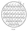
- Figur 8: Querschnitt durch einen Feststoff Gas-oder Flüssigkeitswärmetauscher
- Figur 9: Viereckigen Rohreinsatz für Wärmetauscher
- Figur 10: Viereckigen Rohreinsatz für Wärmetauscher
- Figur 11: Dreieckiger Rohreinsatz für Wärmetauscher
- Figure 1: Square tube with ribs;
- Figure 2: Square tube with conveyor and storage ribs;
- Figure 3: triangular tube with ribs;
- Figure 4: triangular tube with conveying and storage ribs;
- Figure 5: Longitudinal section through a solid-solid heat exchanger
- Figure 6: Cross section through a solid-to-solid heat exchanger with triangular tubes
- Figure 7: Cross section through a solid-solid heat exchanger with square tubes
- Figure 8: Cross section through a solid gas or liquid heat exchanger
- Figure 9: Square tube insert for heat exchangers
- Figure 10: Square tube insert for heat exchangers
- Figure 11: Triangular tube insert for heat exchangers
In Fig. 1 ist schematisch ein erfindungsgemäßes Rohr 1 mit quadratischem Querschnitt dargestellt. Zum Transport des Feststoffes genügt es bei waagerecht liegendem Rohr, wenn auf einer Innenseite rechteckige Förderrippen 2 aufgeschweißt sind. Insbesondere kann auf Schikanen parallel zur Rohrachse im Normalfall verzichetet werden.In Fig. 1, a tube 1 according to the invention is shown schematically with a square cross section. When the pipe is horizontal, it is sufficient to transport the solid if rectangular conveyor ribs 2 are welded onto an inside. In particular, baffles parallel to the pipe axis can normally be dispensed with.
In Fig. 2 ist in Quer- und Längsschnitt ein Vierkantrohr 1 mit Förder- 2 und Staurippen 3 dargestellt.In Fig. 2, a square tube 1 with conveyor 2 and baffle
Auch bei einem Dreieckrohr 4, in Fig. 3 hier mit gleichseitigem Querschnitt, ist es normalerweise ausreichend, wenn an einer Innenseite Förderrippen 5 vorhanden sind.Even with a
Fig. 4 zeigt ein Dreieckrohr 4 mit Förderrippen 5 und Staurippen 6.4 shows a
Die Länge der ebenen Flächen im Querschnitt beträgt besonders bevorzugt 80 bis 200 mm.The length of the flat surfaces in cross section is particularly preferably 80 to 200 mm.
In vielen Fällen werden die erfindungsgemäßen Rohre zur Vergrößerung der Wärmeaustauschfläche parallel geschaltet. Ein Längsschnitt durch einen solchen Wärmeaustauscher ist in Fig. 5 dargestellt. Die zusammengeschalteten Rohre 10 sind im Normalfall mit einer zylindrischen Hülle 11 umgeben. Der Reaktor wird waagerecht liegend betrieben. In diesem Beispiel soll ein Wärmeaustausch zwischen zwei festen Produkten stattfinden. Das wärmeabgebende Produkt wird in diesem Beispiel über den Einfülltrichter 12 aufgegeben und durchläuft den Reaktor von links nach rechts. Spiegelbildlich dazu ist auf der rechten Seite (hier nicht gezeichnet) eine analoge Aufgabevorrichtung für das kalte Produkt vorhanden; während des Durchlaufes durch die Rohre 10 von rechts nach links nimmt es Wärme auf und tritt über die Austrittsöffnung 13 wieder aus dem Wärmetauscher aus. Die Produktaufgabevorrichtung 14 bewirkt eine gleichmäßige Zudosierung. Abgestimmt auf die Fördervorrichtungen 15 in den Rohren ist durch die Dosierung 14 immer gewährleistet, daß die Füllhöhe in den Rohren 10 auf der ganzen Länge immer konstant bleibt, und daß auch alle Rohre, die vom gleichen Produkt durchströmt werden, gleich gefüllt sind, allenfalls an den äußeren Rohren des Einsatzes kann eine Korrektur der Menge erforderlich sein, da diese Rohre nicht allseitig in gleicher Weise an Wärmeübergang beteiligt sind. Ein Schnitt 7 - 7 durch den Wärmeaustauscher in Fig. 5 mit Dreieckrohren ist in Fig. 6, mit quadratischen Rohren in Fig. 7 dargestellt. Die Rohre 10a werden von dem aufzuheizenden Produkt, die Rohre 10b von dem abzukühlenden Produkt in entgegengesetzter Richtung durchströmt.In many cases, the tubes according to the invention are connected in parallel in order to enlarge the heat exchange surface. A longitudinal section through such a heat exchanger is shown in Fig. 5. The
Während bei Feststoff/Festoffwärmetauschern die von den beiden Medien durchströmten Rohre größenordnungsmäßig gleich gefüllt sind und gleichen Querschnitt haben, können bei einem Reaktor mit einem Wärmeübergang zwischen einem festen und einem flüssigen oder gasförmigen Medium (Fig. 8) die Querschnittsflächen auch unterschiedlich sein. Die Rohre 12 sind in diesem Fall bandartig zusammengefaßt; durch sie wird das feste Medium geführt. Sie sind allseitig von dem Heiz- oder Kühlgas oder der Flüssigkeit umströmt. Auf die dichteste Packung wurde hier verzichtet, um die Strömungsgeschwindigkeit z.B. des Gases herabzusetzen.While in solid / solid heat exchangers the pipes through which the two media flow are of the same order of magnitude and have the same cross-section, in a reactor with heat transfer between a solid and a liquid or gaseous medium (FIG. 8) the cross-sectional areas can also be different. The
Bei den erfindungsgemäßen Wärmeaustauschern ist es möglich, die Einsätze scheibenweise aus gleichen Elementen aufzubauen. Bei Rohren mit einem quadratischen Querschnitt wie in Fig. 9 oder 10, werden zwei Bleche 20, 21 rechtwinklig gefaltet und an ihren Enden verschweißt 22 oder verschraubt 22a.In the heat exchangers according to the invention, it is possible to construct the inserts in disks from the same elements. In pipes with a square cross section as in FIG. 9 or 10, two
Selbst wenn dort, wo zwei Kanten aneinanderstoßen, in manchen Bereichen ein kleiner Spalt bleibt, wird die Funktionsweise der Wärmeaustauschrohre dadurch kaum gestört, da durch alle von den Platten 20, 21 gebildeten Rohre der gleiche Produktstrom geht und durch die Rotation sich kein Überschuß zwischen zwei Rohren ausbilden kann. Baut man aus Einsätzen nach Fig. 9 einen Wärmeaustauscher auf, so sind die Querschnittsflächen für die beiden Medien gleich. Ein solcher Wärmeaustauscher ist auch mit Einsätzen nach Fig. 10 erreichbar, wenn die Einsätze an ihren Spitzen zusammenstoßen und außen miteinander verschweißt oder verschraubt sind. Einsätze nach Fig. 10 können jedoch auch so zusammengeschaltet werden, daß die Spitzen des oberen Einsatzes in die "Täler" des unteren Einsatzes fallen und so ein beliebig einstellbarer Spalt zwischen beiden Einsätzen entsteht. Dieser Aufbau wird besonders dann bevorzugt, wenn der durch einen Einsatz nach Fig. 10 strömende feste Stoff seine Wärme an eine Flüssigkeit oder ein Gas abgebem bzw. aufnehmen soll, für das natürlich keine rohrförmige Führung notwendig ist. Bei einem flüssigen Medium kann der Spalt zwischen zwei Einsätzen nach Fig. 10 klein sein. Handelt es sich bei dem zweiten Medium um ein Gas, kann es sinnvoll sein, wenn an den Platteneinsätzen nach Fig. 10 außen Rippen vorhanden sind, um die Wärmeaustauschfläche zu vergrößern.Even if there is a small gap in some areas where two edges meet, the functioning of the heat exchange tubes is hardly disturbed, since the same product flow goes through all the tubes formed by the
Die gleicne Vielfalt wie bei Platten aus viereckigen Rohren nach Fig. 10 kann auch bei Platten mit dreieckigen Rohren nach Fig. 11 erreicht werden. Auch hier genügt es normalerweise wieder, wenn die beiden Platten 23, 24 an ihren Enden 25 verschweißt oder 25 a) verschraubt sind. Werden diese Platten dicht aufeinander gestapelt und seitlich miteinander verschweißt oder verschraubt, erhält man einen Wärmeaustauscher, dessen Querschnittsfläche für beide Medien verhältnismäßig gleich ist und der besonders für einen Feststoff/ Feststoffwärmetauscher in Frage kommt. Kommt es dagegen zu einem Wärmeübergang auf ein flüssiges oder gasförmiges Medium, so können die einzelnen Abstände auch in einem größeren Abstand voneinander angebracht sein, wie es beispielsweise auch in Fig. 8 angedeutet ist, oder es können auch die Einsätze nach Fig. 11 so zusammengesetzt werden, daß die Spitzen ineinander greifen bzw. die ebenen Grundflächen einander gegenüber stehen, wodurch sich präzise sehr kleine Abstände einhalten lassen. Bei einer Reparatur am Wärmeaustauscherbündel ist die Wartungsfreundlichkeit der erfindungsgemäßen Einsätze besonders auffällig.The same variety as with plates made of square tubes according to FIG. 10 can also be achieved with plates with triangular tubes according to FIG. 11. Again, it is usually sufficient if the two
Generell läßt sich sagen, daß sich mit diesen Rohren Wärmeübergangszahlen über 100 Wm-2K-1 bezogen auf die ganze Rohrfläche erzielen lassen.In general, it can be said that these pipes can achieve heat transfer coefficients of over 100 Wm -2 K -1 based on the entire pipe area.
Claims (8)
Applications Claiming Priority (2)
| Application Number | Priority Date | Filing Date | Title |
|---|---|---|---|
| DE19803027187 DE3027187A1 (en) | 1980-07-18 | 1980-07-18 | PIPE FOR INDIRECT HEAT TREATMENT OF GIANT MATERIALS, HEAT EXCHANGERS COMPOSED FROM SUCH PIPES AND COMPONENTS FOR THE PRODUCTION OF THE TUBE BUNDLE |
| DE3027187 | 1980-07-18 |
Publications (3)
| Publication Number | Publication Date |
|---|---|
| EP0044476A2 true EP0044476A2 (en) | 1982-01-27 |
| EP0044476A3 EP0044476A3 (en) | 1982-09-22 |
| EP0044476B1 EP0044476B1 (en) | 1985-05-22 |
Family
ID=6107476
Family Applications (1)
| Application Number | Title | Priority Date | Filing Date |
|---|---|---|---|
| EP81105348A Expired EP0044476B1 (en) | 1980-07-18 | 1981-07-09 | Tube for the indirect heating of easy flowing material and heat exchanger composed of such tubes |
Country Status (3)
| Country | Link |
|---|---|
| EP (1) | EP0044476B1 (en) |
| DE (2) | DE3027187A1 (en) |
| ES (1) | ES504077A0 (en) |
Cited By (3)
| Publication number | Priority date | Publication date | Assignee | Title |
|---|---|---|---|---|
| EP0370144A1 (en) * | 1987-09-03 | 1990-05-30 | Kawasaki Jukogyo Kabushiki Kaisha | Coal-moisture control process |
| EP2348272A3 (en) * | 2010-01-22 | 2015-08-26 | Technische Universität Darmstadt | Regenerative heat exchanger and method for transferring heat between two solids |
| CN115388625A (en) * | 2022-08-30 | 2022-11-25 | 湖南越洋药业有限公司 | Be applied to recoil rotation type drying equipment of methylprednisolone production |
Families Citing this family (1)
| Publication number | Priority date | Publication date | Assignee | Title |
|---|---|---|---|---|
| CN115388624B (en) * | 2022-08-30 | 2023-06-13 | 湖南越洋药业有限公司 | Rotary adjustable drying equipment applied to methylprednisolone production |
Citations (8)
| Publication number | Priority date | Publication date | Assignee | Title |
|---|---|---|---|---|
| FR489266A (en) * | 1918-03-12 | 1919-01-11 | Gio Ansaldo & Cie | Refrigerant tube bundle with circulation of a liquid outside and a fluid inside |
| GB252373A (en) * | 1925-05-19 | 1927-04-14 | Simmon Maschf Hans | Process and apparatus for the exchange of heat between gaseous, vapour like or liquid bodies |
| US1769412A (en) * | 1928-06-09 | 1930-07-01 | Traylor Engineering & Mfg Co | Rotary tube cooler |
| US2899176A (en) * | 1959-08-11 | Heat exchanger | ||
| US3602298A (en) * | 1969-04-25 | 1971-08-31 | Mecislaus Joseph Ciesielski | Heat exchanger |
| DE1778226A1 (en) * | 1968-04-09 | 1971-10-14 | Ljungberg Bror Gustaf | Smoke or flame pipe, especially for boilers |
| DE2109308A1 (en) * | 1971-02-26 | 1972-09-07 | Linde Ag | Method for producing a laminated core, in particular a plate heat exchanger |
| DE2946904B1 (en) * | 1979-11-21 | 1981-02-26 | Bayer Ag, 5090 Leverkusen | Rotatable heat exchanger tube that can be heated or cooled from the outside for heat treatment of powdery to granular, free-flowing, possibly slurried material |
-
1980
- 1980-07-18 DE DE19803027187 patent/DE3027187A1/en not_active Withdrawn
-
1981
- 1981-07-09 DE DE8181105348T patent/DE3170594D1/en not_active Expired
- 1981-07-09 EP EP81105348A patent/EP0044476B1/en not_active Expired
- 1981-07-17 ES ES504077A patent/ES504077A0/en active Granted
Patent Citations (8)
| Publication number | Priority date | Publication date | Assignee | Title |
|---|---|---|---|---|
| US2899176A (en) * | 1959-08-11 | Heat exchanger | ||
| FR489266A (en) * | 1918-03-12 | 1919-01-11 | Gio Ansaldo & Cie | Refrigerant tube bundle with circulation of a liquid outside and a fluid inside |
| GB252373A (en) * | 1925-05-19 | 1927-04-14 | Simmon Maschf Hans | Process and apparatus for the exchange of heat between gaseous, vapour like or liquid bodies |
| US1769412A (en) * | 1928-06-09 | 1930-07-01 | Traylor Engineering & Mfg Co | Rotary tube cooler |
| DE1778226A1 (en) * | 1968-04-09 | 1971-10-14 | Ljungberg Bror Gustaf | Smoke or flame pipe, especially for boilers |
| US3602298A (en) * | 1969-04-25 | 1971-08-31 | Mecislaus Joseph Ciesielski | Heat exchanger |
| DE2109308A1 (en) * | 1971-02-26 | 1972-09-07 | Linde Ag | Method for producing a laminated core, in particular a plate heat exchanger |
| DE2946904B1 (en) * | 1979-11-21 | 1981-02-26 | Bayer Ag, 5090 Leverkusen | Rotatable heat exchanger tube that can be heated or cooled from the outside for heat treatment of powdery to granular, free-flowing, possibly slurried material |
Cited By (4)
| Publication number | Priority date | Publication date | Assignee | Title |
|---|---|---|---|---|
| EP0370144A1 (en) * | 1987-09-03 | 1990-05-30 | Kawasaki Jukogyo Kabushiki Kaisha | Coal-moisture control process |
| EP2348272A3 (en) * | 2010-01-22 | 2015-08-26 | Technische Universität Darmstadt | Regenerative heat exchanger and method for transferring heat between two solids |
| CN115388625A (en) * | 2022-08-30 | 2022-11-25 | 湖南越洋药业有限公司 | Be applied to recoil rotation type drying equipment of methylprednisolone production |
| CN115388625B (en) * | 2022-08-30 | 2023-06-13 | 湖南越洋药业有限公司 | Backflushing rotary type drying equipment applied to methylprednisolone production |
Also Published As
| Publication number | Publication date |
|---|---|
| ES8206011A1 (en) | 1982-06-16 |
| ES504077A0 (en) | 1982-06-16 |
| EP0044476A3 (en) | 1982-09-22 |
| EP0044476B1 (en) | 1985-05-22 |
| DE3027187A1 (en) | 1982-02-11 |
| DE3170594D1 (en) | 1985-06-27 |
Similar Documents
| Publication | Publication Date | Title |
|---|---|---|
| DE2124010C3 (en) | Heat exchangers for heating, drying or cooling | |
| DE2544916B2 (en) | Device for cooling food | |
| EP0144092A2 (en) | Mixing and kneading machine | |
| DE2232386B2 (en) | Device for cold drying of gas, in particular air | |
| DE3136589A1 (en) | TEMPERATURE STATIC MIXER AND REACTOR | |
| DE2804106C2 (en) | Heat exchanger | |
| DE2951352C2 (en) | Flat tube heat exchanger | |
| EP0019244B1 (en) | Apparatus and process for pyrolyzing waste products | |
| DE2100248C3 (en) | Device for heat, cold and / or material treatment of granular, free-flowing goods | |
| DE2048226B2 (en) | Rotary kiln for the production of hydrofluoric acid | |
| EP2976589A1 (en) | Pipe bundle recuperator on a sintering furnace and thermal transfer method having a sintering furnace and having a pipe bundle recuperator | |
| DE2256711A1 (en) | COOLING PROCESS AND DEVICE | |
| DE2853054B2 (en) | Device for pressing out flowable masses | |
| EP0044476B1 (en) | Tube for the indirect heating of easy flowing material and heat exchanger composed of such tubes | |
| DE19849099C2 (en) | Device for the continuous tempering of cocoa butter-containing or similar fat-containing masses to be processed | |
| DE2550035C3 (en) | Heat exchanger with a plurality of heat exchange medium flow tubes arranged at a distance from one another | |
| DE2946904C2 (en) | Rotatable heat exchanger tube that can be heated or cooled from the outside for heat treatment of powdery to granular, free-flowing, possibly slurried material | |
| DE1298083B (en) | Screw machine | |
| DE1567297C3 (en) | Device for tempering a sugar filling compound | |
| DE2164012C2 (en) | Process and rotary drum for countercurrent treatment of flowable solids with a flowing liquid | |
| EP0004081B1 (en) | Shaft-type cooler | |
| DE2349305C3 (en) | Device for carrying out a physico-chemical exchange process | |
| DE1542151C3 (en) | Wiper for thin film reaction or evaporation tube | |
| DE102005045051A1 (en) | Indirectly heated rotary kiln suitable for high temperatures comprises multiple barrels within a common furnace | |
| DE4225905C2 (en) | Food heat exchangers |
Legal Events
| Date | Code | Title | Description |
|---|---|---|---|
| PUAI | Public reference made under article 153(3) epc to a published international application that has entered the european phase |
Free format text: ORIGINAL CODE: 0009012 |
|
| 17P | Request for examination filed |
Effective date: 19810709 |
|
| AK | Designated contracting states |
Designated state(s): BE CH DE FR GB IT LI NL |
|
| KL | Correction list |
Free format text: 82/03 TITELBLATT |
|
| PUAL | Search report despatched |
Free format text: ORIGINAL CODE: 0009013 |
|
| AK | Designated contracting states |
Designated state(s): BE CH DE FR GB IT LI NL |
|
| RAP1 | Party data changed (applicant data changed or rights of an application transferred) |
Owner name: KELLER, WOLFGANG |
|
| GRAA | (expected) grant |
Free format text: ORIGINAL CODE: 0009210 |
|
| AK | Designated contracting states |
Designated state(s): BE CH DE FR GB IT LI NL |
|
| PG25 | Lapsed in a contracting state [announced via postgrant information from national office to epo] |
Ref country code: NL Effective date: 19850522 Ref country code: IT Free format text: LAPSE BECAUSE OF FAILURE TO SUBMIT A TRANSLATION OF THE DESCRIPTION OR TO PAY THE FEE WITHIN THE PRESCRIBED TIME-LIMIT;WARNING: LAPSES OF ITALIAN PATENTS WITH EFFECTIVE DATE BEFORE 2007 MAY HAVE OCCURRED AT ANY TIME BEFORE 2007. THE CORRECT EFFECTIVE DATE MAY BE DIFFERENT FROM THE ONE RECORDED. Effective date: 19850522 Ref country code: FR Free format text: THE PATENT HAS BEEN ANNULLED BY A DECISION OF A NATIONAL AUTHORITY Effective date: 19850522 Ref country code: BE Effective date: 19850522 |
|
| REF | Corresponds to: |
Ref document number: 3170594 Country of ref document: DE Date of ref document: 19850627 |
|
| PG25 | Lapsed in a contracting state [announced via postgrant information from national office to epo] |
Ref country code: LI Effective date: 19850731 Ref country code: CH Effective date: 19850731 |
|
| NLV1 | Nl: lapsed or annulled due to failure to fulfill the requirements of art. 29p and 29m of the patents act | ||
| EN | Fr: translation not filed | ||
| GBPC | Gb: european patent ceased through non-payment of renewal fee | ||
| REG | Reference to a national code |
Ref country code: CH Ref legal event code: PL |
|
| PLBE | No opposition filed within time limit |
Free format text: ORIGINAL CODE: 0009261 |
|
| STAA | Information on the status of an ep patent application or granted ep patent |
Free format text: STATUS: NO OPPOSITION FILED WITHIN TIME LIMIT |
|
| 26N | No opposition filed | ||
| PG25 | Lapsed in a contracting state [announced via postgrant information from national office to epo] |
Ref country code: GB Free format text: LAPSE BECAUSE OF NON-PAYMENT OF DUE FEES Effective date: 19881118 |
|
| PGFP | Annual fee paid to national office [announced via postgrant information from national office to epo] |
Ref country code: DE Payment date: 19911021 Year of fee payment: 11 |
|
| PG25 | Lapsed in a contracting state [announced via postgrant information from national office to epo] |
Ref country code: DE Effective date: 19930401 |