EP0042970B1 - Buchsenleiste - Google Patents
Buchsenleiste Download PDFInfo
- Publication number
- EP0042970B1 EP0042970B1 EP81103875A EP81103875A EP0042970B1 EP 0042970 B1 EP0042970 B1 EP 0042970B1 EP 81103875 A EP81103875 A EP 81103875A EP 81103875 A EP81103875 A EP 81103875A EP 0042970 B1 EP0042970 B1 EP 0042970B1
- Authority
- EP
- European Patent Office
- Prior art keywords
- contact
- spring
- base member
- cavity
- side wall
- Prior art date
- Legal status (The legal status is an assumption and is not a legal conclusion. Google has not performed a legal analysis and makes no representation as to the accuracy of the status listed.)
- Expired
Links
- 238000003825 pressing Methods 0.000 claims description 3
- 239000002184 metal Substances 0.000 claims description 2
- 239000012212 insulator Substances 0.000 claims 2
- 230000000717 retained effect Effects 0.000 claims 1
- 230000000295 complement effect Effects 0.000 description 3
- 238000004804 winding Methods 0.000 description 2
- 230000000694 effects Effects 0.000 description 1
- 238000002347 injection Methods 0.000 description 1
- 239000007924 injection Substances 0.000 description 1
- 238000004519 manufacturing process Methods 0.000 description 1
- 230000005405 multipole Effects 0.000 description 1
- 230000000149 penetrating effect Effects 0.000 description 1
- 238000005476 soldering Methods 0.000 description 1
- 239000000243 solution Substances 0.000 description 1
- 239000000725 suspension Substances 0.000 description 1
Images


Classifications
-
- H—ELECTRICITY
- H01—ELECTRIC ELEMENTS
- H01R—ELECTRICALLY-CONDUCTIVE CONNECTIONS; STRUCTURAL ASSOCIATIONS OF A PLURALITY OF MUTUALLY-INSULATED ELECTRICAL CONNECTING ELEMENTS; COUPLING DEVICES; CURRENT COLLECTORS
- H01R13/00—Details of coupling devices of the kinds covered by groups H01R12/70 or H01R24/00 - H01R33/00
- H01R13/40—Securing contact members in or to a base or case; Insulating of contact members
- H01R13/42—Securing in a demountable manner
-
- H—ELECTRICITY
- H01—ELECTRIC ELEMENTS
- H01R—ELECTRICALLY-CONDUCTIVE CONNECTIONS; STRUCTURAL ASSOCIATIONS OF A PLURALITY OF MUTUALLY-INSULATED ELECTRICAL CONNECTING ELEMENTS; COUPLING DEVICES; CURRENT COLLECTORS
- H01R13/00—Details of coupling devices of the kinds covered by groups H01R12/70 or H01R24/00 - H01R33/00
- H01R13/02—Contact members
- H01R13/26—Pin or blade contacts for sliding co-operation on one side only
-
- H—ELECTRICITY
- H01—ELECTRIC ELEMENTS
- H01R—ELECTRICALLY-CONDUCTIVE CONNECTIONS; STRUCTURAL ASSOCIATIONS OF A PLURALITY OF MUTUALLY-INSULATED ELECTRICAL CONNECTING ELEMENTS; COUPLING DEVICES; CURRENT COLLECTORS
- H01R13/00—Details of coupling devices of the kinds covered by groups H01R12/70 or H01R24/00 - H01R33/00
- H01R13/40—Securing contact members in or to a base or case; Insulating of contact members
- H01R13/405—Securing in non-demountable manner, e.g. moulding, riveting
- H01R13/41—Securing in non-demountable manner, e.g. moulding, riveting by frictional grip in grommet, panel or base
Definitions
- the invention relates to a socket strip of the embodiment specified in the preamble of claim 1, as is known from US-A-4 036 544.
- Socket strips are known (DE-U-7705029), the insulating bodies of which contain slot-shaped contact chambers, each with a single-leg contact spring arranged therein.
- the contact spring rests on a vertically displaceable pressure piece, which, after inserting a contact pin, presses the spring leg against the contact pin by means of slide actuation, whereby the latter is clamped between a wall of the contact chamber and the spring leg.
- the housing of an exemplary embodiment consists of an insulating plate containing upstanding contact springs with a cap-like insulating body fastened thereon, in which the contact chambers open on the underside are contained. There is an opening assigned to each contact chamber in the cover wall for inserting the contact pin.
- the insulating housing has several individual sleeves, each containing a contact spring. These sleeves are fastened in bores of a common base plate in such a way that they form a multipole socket strip with contact springs arranged in two rows.
- the insulating body of such socket strips can also be formed in one piece (GB-A-1 463 515).
- the contact chambers in such insulating housings on the plug side are completely open.
- they are inserted with their rear contact connection parts first into the contact chambers in such a way that they are self-locking and their spring legs rest on one side of the chamber in the rest position.
- the same chamber side has a molded-in guide groove for the contact pin of the complementary connector strip, but the guide groove is narrower than the end of the contacting spring.
- the attachment of the contact springs by pressing their contact connection parts into corresponding openings in the insulating housings or contact chambers is critical here because these parts are subjected to high thermal and mechanical loads during the connection to the connecting wires by soldering and / or winding and can thereby lose their tight fit.
- the invention has for its object to provide an inexpensive socket strip with contact springs that can be easily inserted mechanically in the insulating body and securely attached therein. This object is achieved according to the invention by the design measures specified in the characterizing part of claim 1. An advantageous embodiment of the socket strip is specified in claim 2.
- the contact spring has a wider base part, which offers contact surfaces for simple mechanical pressing of the contact spring into corresponding slots in the contact chamber in the insulating body. Due to the incisions in the base part and the arrangement of the contact connection part that is cranked out of the sheet metal plane, a certain elasticity of the tabs is achieved, so that the load that occurs on the connection part when connecting with connecting wires no longer has a direct effect on the fastening of the contact spring or its base part.
- the cranking out of the contact connection part also makes it possible to arrange the latter in alignment with the connection part of the straight contact pin of the complementary connector strip.
- the plugs and socket strips have no offset to one another when arranged on printed circuit boards with an identical hole pattern.
- only one injection mold is required for the production of the insulating body, which molds the lateral slots for the base part in such a way that a simple, quick and secure press-fit fastening of the contact springs is ensured.
- the female header is generally designated 1. It consists of an integrally molded insulating body 2 with a plurality of contact chambers 4 each containing a contact spring 3.
- the contact chambers 4 are preferably arranged in two rows running parallel to one another and they serve to receive the contact pins 5 of a complementary connector strip.
- the contact spring 3 is formed in one leg. It consists of a relatively wide base part 6 with a narrower spring leg 7, which has a reduced sheet thickness compared to the base part 6.
- the spring leg 7 is obliquely away from the base edge.
- the spring end 8, which is again wider in size, is slightly bent back about half out of the leg plane, as a result of which the contact-making contact area is formed.
- the contact terminal 9 which is preferably designed as a winding post, is arranged on the side of the base part 6 opposite the spring leg 7.
- the base part 6 is slightly cut at the bottom and the contact connection 9 on the cranked out the contacting contact area of the spring end 8, whereby two short, free-standing tabs 10 are formed.
- Such contact elements can be produced hanging from the tape or individually, automatically fed to the socket body and equipped with its contact chambers.
- the contact spring 3 can be fastened in the insulating body 2 of the socket strip 1 by means of its base part 6.
- the base part 6 is pressed from the plug-in side 11 of the insulating body 2 with the contact connection 9 first into two oppositely arranged slots 12 of the contact chamber 4, which is completely open at the top, down to the bottom.
- the slots 12 are a little wider at the open start and slightly narrower at the lower end than the sheet thickness of the base part 6.
- the contact connection 9 penetrates a corresponding bore 13 in the lower part of the insulating body, which at an expedient embodiment is provided with a molded pin 14 assigned to each contact chamber 4, from which the end of the connection protrudes freely.
- the bore 13 containing the contact connection 9 is advantageously arranged in an aligned extension of the receptacle for the contact pin 5.
- the receptacle for the contact pin 5 consists of a part of the contact chamber 4, in which the spring leg 7 can be freely deflected and a guide groove 15 which prevents lateral inclination. This is formed with a smaller width than the end of the contact spring 3 on the chamber side in the insulating body 2, on which the spring leg 7 bears with more or less great prestress. So that its pressure force can be fully effective in function, the depth of the guide groove 15 is designed such that the contact pin 5 penetrating into the receptacle reliably lifts the spring leg 7 or its contacting spring end 8 from the chamber wall.
Landscapes
- Coupling Device And Connection With Printed Circuit (AREA)
- Details Of Connecting Devices For Male And Female Coupling (AREA)
- Connector Housings Or Holding Contact Members (AREA)
- Manufacturing Of Electrical Connectors (AREA)
Description
- Die Erfindung betrifft eine Buchsenleiste der im Oberbegriff des Anspruchs 1 näher bezeichneten Ausführung, wie sie aus der US-A-4 036 544 bekannt ist.
- Es sind Buchsenleisten bekannt (DE-U-7705029), deren Isolierkörper schlitzförmige Kontaktkammern mit je einer darin angeordneten, einschenkligen Kontaktfeder enthalten. Die Kontaktfeder liegt jeweils an einem vertikalverschieblich gelagerten Druckstück an, das nach dem Einstecken eines Kontaktstiftes mittels Schieberbetätigung den Federschenkel gegen den Kontaktstift andrückt, wodurch letzterer zwischen einer Wandung der Kontaktkammer und dem Federschenkel eingeklemmt wird.
- Bei einer beispielsweise für den Einsatz in Kraftfahrzeugen konzipierten Buchsenleiste (DE-A-2 222 359), besteht das Gehäuse eines Ausführungsbeispieies aus einer aufragende Kontaktfedern enthaltenden Isolierplatte mit einem darauf befestigten, kappenartigen Isolierkörper, in dem die an der Unterseite offenen Kontaktkammern enthalten sind. In der Deckwand befindet sich ein jeder Kontaktkammer zugeordneter Durchbruch zum Einstecken des Kontaktstiftes.
- Bei der Buchsenleiste nach der US-A-4 036 544 weist das Isoliergehäuse mehrere einzelne, je eine Kontaktfeder enthaltende Hülsen auf. Diese Hülsen sind so in Bohrungen einer gemeinsamen Grundplatte befestigt, dass sie eine mehrpolige Buchsenleiste mit in zwei Reihen angeordneten Kontaktfedern bilden. Die Isolierkörper von derartigen Buchsenleisten können aber auch einstükkig ausgebildet sein (GB-A-1 463 515).
- Hiervon unabhängig sind die Kontaktkammern bei solchen Isoliergehäusen an der Steckseite gänzlich offen. Bei Montage der Kontaktfedern werden diese mit ihren rückwärtigen Kontaktanschlussteilen voran so in die Kontaktkammern eingesetzt, dass sie sich darin selbsthemmend halten und ihre Federschenkel in der Ruhelage an einer Kammerseite anliegen. Dieselbe Kammerseite weist eine eingeformte Führungsnut für den Kontaktstift der komplementären Steckerleiste auf, wobei die Führungsnut jedoch schmaler ist als das Ende der kontaktgebenden Feder.
- Die Befestigung der Kontaktfedern durch Einpressen ihrer Kontaktanschlussteilg, in entsprechende Öffnungen der Isoliergegäuse bzw. Kontaktkammern ist hier kritisch, weil diese Teile bei dem durch Löten und/oder Anwickeln erfolgenden Verbinden mit Anschlussdrähten thermisch und mechanisch stark belastet werden und dabei ihren Festsitz verlieren können.
- Der Erfindung liegt die Aufgabe zugrunde, eine kostengünstig herstellbare Buchsenleiste mit Kontaktfedern zu schaffen, die auf einfache Weise maschinell in den Isolierkörper eingesetzt und darin sicher befestigt werden können. Diese Aufgabe wird erfindungsgemäss durch die im kennzeichnenden Teil des Anspruchs 1 angegebenen konstruktiven Massnahmen gelöst. Eine vorteilhafte Ausbildung der Buchsenleiste ist im Anspruch 2 angegeben.
- Die gefundene Lösung bietet verschiedene Vorzüge. Die Kontaktfeder weist gegenüber ihrem Federschenkel ein breiteres Basisteil auf, das Angriffsflächen für ein einfaches maschinelles Einpressen der Kontaktfeder in entsprechende Schlitze der Kontaktkammer im Isolierkörper bietet. Durch die Einschnitte im Basisteil und die aus der Blechebene herausgekröpfte Anordnung des Kontaktanschlussteiles wird eine gewisse Elastizität der Lappen erreicht, so dass die beim Verbinden mit Anschlussdrähten am Anschlussteil entstehende Belastung sich nicht mehr unmittelbar auf die Befestigung der Kontaktfeder bzw. ihres Basisteiles auswirkt. Das Herauskröpfen des Kontaktanschlussteiles gestattet es auch, letzteren fluchtend zum Anschlussteil des geraden Kontaktstiftes der komplementären Steckerleiste anzuordnen. Dies ist insofern von Vorteil, weil die Stecker und Buchsenleisten bei der Anordnung auf gedruckten Leiterplatten mit identischem Lochraster keinen Versatz zueinander haben. Schliesslich ist für die Herstellung des Isolierkörpers nur ein Spritzwerkzeug erforderlich, welches die seitlichen Schlitze für das Basisteil so ausformt, dass eine einfache, schnelle und sichere Presssitzbefestigung der Kontaktfedern gewährleistet ist.
- Die Erfindung wird anhand eines in Zeichnungen dargestellten Ausführungsbeispiels wie folgt näher beschrieben. In den Zeichnungen zeigt:
- Fig. 1 die Buchsenleiste mit eingestecktem Kontaktstift in einer Querschnittsansicht
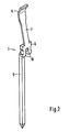
- Fig. 2 eine Kontaktfeder der Buchsenleiste in perspektivischer Darstellung
- Fig. 3 einen ausgeschnittenen Teil der Buchsenleiste mit Blick auf die in einer Kontaktkammer steckende Kontaktfeder, in perspektivischer Ansicht.
- In den Figuren 1 und 3 ist die Buchsenleiste allgemein mit 1 bezeichnet. Sie besteht aus einem einstückig gespritzten Isolierkörper 2 mit mehreren, je eine Kontaktfeder 3 enthaltenden Kontaktkammer 4. Die Kontaktkammern 4 sind vorzugsweise in zwei parallel zueinander verlaufenden Reihen angeordnet und sie dienen zur Aufnahme der Kontaktstifte 5 einer komplementären Steckerleiste.
- Wie Fig. 2 zeigt, ist die Kontaktfeder 3 einschenklig ausgebildet. Sie besteht aus einem relativ breiten Basisteil 6 mit sich schmaler fortsetzendem Federschenkel 7, der gegenüber dem Basisteil 6 eine reduzierte Blechdicke aufweist. Von der Basiskante steht der Federschenkel 7 schräg weg. Das wieder breiter bemessene Federende 8 ist etwa zur Hälfte aus der Schenkelebene heraus leicht zurückgebogen, wodurch der kontaktgebende Anlagebereich gebildet wird.
- Auf der dem Federschenkel 7 gegenüberstehenden Seite des Basisteils 6 ist der vorzugsweise als Wickelpfosten ausgebildete Kontaktanschluss 9 angeordnet. Um eine gewisse Federung zu erreichen, ist das Basisteil 6 unten etwas eingeschnitten und der Kontaktanschluss 9 auf der den kontaktgebenden Anlagebereich des Federendes 8 aufweisenden Seite herausgekröpft, wodurch zwei kurze, freistehende Lappen 10 gebildet werden. Solche Kontaktelemente lassen sich am Band hängend oder auch einzeln herstellen, dem Buchsenkörper automatisch zuführen und dessen Kontaktkammern bestücken.
- Die Kontaktfeder 3 lässt sich mittels ihres Basisteils 6 in dem Isolierkörper 2 der Buchsenleiste 1 befestigen. Bei der Montage wird das Basisteil 6 von der Steckseite 11 des Isolierkörpers 2 aus mit dem Kontaktanschluss 9 voran in zwei gegenüberliegend angeordnete Schlitze 12 der oben vollständig offenen Kontaktkammer 4 bis zum Boden eingedrückt. Wie insbesondere die Fig. 1 zeigt, sind die Schlitze 12 zur Montageerleichterung am offenen Beginn etwas breiter und am unteren Ende etwas schmaler bemessen als die Blechdikke des Basisteils 6. Nach beendeter Montage durchsetzt der Kontaktanschluss 9 eine entsprechende Bohrung 13 im unteren Isolierkörperteil, der bei einem zweckmässigen Ausführungsbeispiel mit einem jeder Kontaktkammer 4 zugeordneten, angespritzten Zapfen 14 versehen ist, aus dem das Ende des Anschlusses frei hervorsteht. In vorteilhafter Weise ist die den Kontaktanschluss 9 enthaltende Bohrung 13 in fluchtender Verlängerung der Aufnahme für den Kontaktstift 5 angeordnet.
- Die Aufnahme für den Kontaktstift 5 besteht aus einem Teil der Kontaktkammer 4, in dem der Federschenkel 7 frei auslenkbar ist und einer seitliches Schrägstecken verhindernden Führungsnut 15. Diese ist mit geringerer Breite als das Ende der Kontaktfeder 3 auf der Kammerseite in den Isolierkörper 2 eingeformt, an welcher sich der Federschenkel 7 mit mehr oder weniger grosser Vorspannung anlegt. Damit dessen Andruckkraft in Funktion voll wirksam werden kann, ist die Tiefe der Führungsnut 15 so ausgelegt, dass der in die Aufnahme eindringende Kontaktstift 5 den Federschenkel 7 bzw. sein kontaktgebendes Federende 8 mit Sicherheit von der Kammerwand abhebt.
Claims (2)
Applications Claiming Priority (2)
| Application Number | Priority Date | Filing Date | Title |
|---|---|---|---|
| DE3023934 | 1980-06-26 | ||
| DE19803023934 DE3023934A1 (de) | 1980-06-26 | 1980-06-26 | Buchsenleiste |
Publications (2)
| Publication Number | Publication Date |
|---|---|
| EP0042970A1 EP0042970A1 (de) | 1982-01-06 |
| EP0042970B1 true EP0042970B1 (de) | 1985-09-04 |
Family
ID=6105519
Family Applications (1)
| Application Number | Title | Priority Date | Filing Date |
|---|---|---|---|
| EP81103875A Expired EP0042970B1 (de) | 1980-06-26 | 1981-05-20 | Buchsenleiste |
Country Status (4)
| Country | Link |
|---|---|
| EP (1) | EP0042970B1 (de) |
| DE (2) | DE3023934A1 (de) |
| ES (1) | ES268064Y (de) |
| GB (1) | GB2079071B (de) |
Cited By (1)
| Publication number | Priority date | Publication date | Assignee | Title |
|---|---|---|---|---|
| DE9105347U1 (de) * | 1991-04-30 | 1992-09-03 | Panduit Gmbh, 6380 Bad Homburg | Steckverbinder |
Families Citing this family (4)
| Publication number | Priority date | Publication date | Assignee | Title |
|---|---|---|---|---|
| US4597625A (en) * | 1984-07-25 | 1986-07-01 | North American Specialties Corporation | Electrical connector |
| US4752246A (en) * | 1986-05-30 | 1988-06-21 | Molex Incorporated | Preloaded spring contact electrical terminal |
| US5411408A (en) * | 1994-08-19 | 1995-05-02 | Molex Incorporated | Electrical connector for printed circuit boards |
| CN105552620A (zh) * | 2015-12-09 | 2016-05-04 | 中国船舶重工集团公司第七二六研究所 | 插针水密包覆增强结构 |
Family Cites Families (4)
| Publication number | Priority date | Publication date | Assignee | Title |
|---|---|---|---|---|
| DE2222359A1 (de) * | 1972-05-06 | 1973-11-22 | Bbc Brown Boveri & Cie | Elektrische steckverbindung |
| GB1463515A (en) * | 1974-08-20 | 1977-02-02 | Trw Inc | Electrical connector assemblies |
| US4036544A (en) * | 1974-10-16 | 1977-07-19 | Bunker Ramo Corporation | Contact for multiple conductor connector |
| DE2707122C2 (de) * | 1976-02-20 | 1982-04-29 | Japan Aviation Electronics Industry, Ltd., Tokyo | Elektrische Kontaktverbindungseinrichtung |
-
1980
- 1980-06-26 DE DE19803023934 patent/DE3023934A1/de not_active Withdrawn
-
1981
- 1981-05-19 GB GB8115346A patent/GB2079071B/en not_active Expired
- 1981-05-20 EP EP81103875A patent/EP0042970B1/de not_active Expired
- 1981-05-20 DE DE8181103875T patent/DE3172117D1/de not_active Expired
- 1981-06-26 ES ES1981268064U patent/ES268064Y/es not_active Expired
Cited By (1)
| Publication number | Priority date | Publication date | Assignee | Title |
|---|---|---|---|---|
| DE9105347U1 (de) * | 1991-04-30 | 1992-09-03 | Panduit Gmbh, 6380 Bad Homburg | Steckverbinder |
Also Published As
| Publication number | Publication date |
|---|---|
| ES268064Y (es) | 1983-12-16 |
| ES268064U (es) | 1983-06-16 |
| GB2079071B (en) | 1985-01-23 |
| GB2079071A (en) | 1982-01-13 |
| DE3023934A1 (de) | 1982-01-14 |
| DE3172117D1 (en) | 1985-10-10 |
| EP0042970A1 (de) | 1982-01-06 |
Similar Documents
| Publication | Publication Date | Title |
|---|---|---|
| EP0793313B1 (de) | Abgewinkelter Einpress-Steck-verbinder zum Einpressen in Bohrungen einer Leiterplatte | |
| DE2406125C3 (de) | Buchsenkontakt | |
| DE69719595T2 (de) | Steckverbinderanordnung | |
| DE69306463T2 (de) | Elektrischer Flachbauverbinder | |
| DE69330110T2 (de) | Elektrischer Verbinder mit verbesserten Kontaktrückhaltemitteln | |
| DE2443476C2 (de) | Elektrisches Verbindungsstück | |
| DE69515388T2 (de) | Elektrische Verbinderklemme und Herstellungsverfahren eines elektrischen Verbinders mit derartigen Klemmen | |
| EP3387709B1 (de) | Leiteranschlussklemme und set aus leiteranschlussklemme und betätigungswerkzeug | |
| DE2426373A1 (de) | Elektrischer verbinder | |
| DE2409075A1 (de) | Elektrischer verbinder | |
| DE2212807C2 (de) | Elektrische Verbinderanordnung | |
| DE3629740C2 (de) | Buchsenartiger elektrischer Anschluß | |
| DE69703926T2 (de) | Steckerelement für Druckkontakt | |
| EP1119885A1 (de) | Anordnung zur kontaktierung eines einen elektrischen anschluss aufweisenden bauteils mit einer elektrischen schaltung | |
| DE69603189T2 (de) | Elektrischer verbinder | |
| DE2360822C2 (de) | Halterung für Sicherungspatronen | |
| EP0333989A2 (de) | Elektrischer Steckverbinder | |
| DE69208456T2 (de) | Verbinder mit Einpressstiften | |
| EP0828320A1 (de) | Steckverbinder | |
| DE2842892A1 (de) | Elektrischer verbinder | |
| DE3812921A1 (de) | Druckknopfschalter | |
| DE29820091U1 (de) | Elektrische Verbindungseinrichtung | |
| DE2363597A1 (de) | Elektrischer stecker | |
| DE20113884U1 (de) | Elektrischer Verbinder für eine Leiterplatte | |
| EP0042970A1 (de) | Buchsenleiste |
Legal Events
| Date | Code | Title | Description |
|---|---|---|---|
| PUAI | Public reference made under article 153(3) epc to a published international application that has entered the european phase |
Free format text: ORIGINAL CODE: 0009012 |
|
| AK | Designated contracting states |
Designated state(s): BE CH DE FR IT |
|
| RBV | Designated contracting states (corrected) |
Designated state(s): BE CH DE FR IT LI |
|
| 17P | Request for examination filed |
Effective date: 19820629 |
|
| ITF | It: translation for a ep patent filed | ||
| RAP1 | Party data changed (applicant data changed or rights of an application transferred) |
Owner name: CANNON ELECTRIC GMBH Owner name: ITT INDUSTRIES INC. |
|
| GRAA | (expected) grant |
Free format text: ORIGINAL CODE: 0009210 |
|
| AK | Designated contracting states |
Designated state(s): BE CH DE FR IT LI |
|
| REF | Corresponds to: |
Ref document number: 3172117 Country of ref document: DE Date of ref document: 19851010 |
|
| ET | Fr: translation filed | ||
| PG25 | Lapsed in a contracting state [announced via postgrant information from national office to epo] |
Ref country code: LI Effective date: 19860531 Ref country code: CH Effective date: 19860531 Ref country code: BE Effective date: 19860531 |
|
| PLBE | No opposition filed within time limit |
Free format text: ORIGINAL CODE: 0009261 |
|
| STAA | Information on the status of an ep patent application or granted ep patent |
Free format text: STATUS: NO OPPOSITION FILED WITHIN TIME LIMIT |
|
| 26N | No opposition filed | ||
| BERE | Be: lapsed |
Owner name: ITT INDUSTRIES INC. Effective date: 19860531 |
|
| REG | Reference to a national code |
Ref country code: CH Ref legal event code: PL |
|
| PG25 | Lapsed in a contracting state [announced via postgrant information from national office to epo] |
Ref country code: FR Free format text: LAPSE BECAUSE OF NON-PAYMENT OF DUE FEES Effective date: 19880129 |
|
| REG | Reference to a national code |
Ref country code: FR Ref legal event code: ST |
|
| PG25 | Lapsed in a contracting state [announced via postgrant information from national office to epo] |
Ref country code: DE Effective date: 19900201 |