EP0042179B1 - Encoder - Google Patents
Encoder Download PDFInfo
- Publication number
- EP0042179B1 EP0042179B1 EP81104660A EP81104660A EP0042179B1 EP 0042179 B1 EP0042179 B1 EP 0042179B1 EP 81104660 A EP81104660 A EP 81104660A EP 81104660 A EP81104660 A EP 81104660A EP 0042179 B1 EP0042179 B1 EP 0042179B1
- Authority
- EP
- European Patent Office
- Prior art keywords
- sensor array
- patterns
- grid patterns
- code plate
- sensor
- Prior art date
- Legal status (The legal status is an assumption and is not a legal conclusion. Google has not performed a legal analysis and makes no representation as to the accuracy of the status listed.)
- Expired
Links
Images


Classifications
-
- H—ELECTRICITY
- H03—ELECTRONIC CIRCUITRY
- H03M—CODING; DECODING; CODE CONVERSION IN GENERAL
- H03M1/00—Analogue/digital conversion; Digital/analogue conversion
- H03M1/12—Analogue/digital converters
- H03M1/22—Analogue/digital converters pattern-reading type
- H03M1/24—Analogue/digital converters pattern-reading type using relatively movable reader and disc or strip
- H03M1/28—Analogue/digital converters pattern-reading type using relatively movable reader and disc or strip with non-weighted coding
- H03M1/285—Analogue/digital converters pattern-reading type using relatively movable reader and disc or strip with non-weighted coding of the unit Hamming distance type, e.g. Gray code
-
- H—ELECTRICITY
- H03—ELECTRONIC CIRCUITRY
- H03M—CODING; DECODING; CODE CONVERSION IN GENERAL
- H03M1/00—Analogue/digital conversion; Digital/analogue conversion
- H03M1/12—Analogue/digital converters
- H03M1/20—Increasing resolution using an n bit system to obtain n + m bits
- H03M1/202—Increasing resolution using an n bit system to obtain n + m bits by interpolation
- H03M1/203—Increasing resolution using an n bit system to obtain n + m bits by interpolation using an analogue interpolation circuit
Definitions
- the present invention relates to an encoder for measuring distances or angles and, more particularly, to an encoder which is capable of providing high precision and good resolution.
- linear encoders and rotary encoders are known.
- the linear encoder is used to measure distances
- the rotary encoder is used to measure angles.
- These two types of encoders are based on essentially the same principle, and differ from each other only according to whether the encoder arrangement is linear or circular.
- the encoders are also classified into optical encoders which utilize light, encoders which utilize magnetism or electromagnetism instead of light, and so on.
- the minimum measurable limit is determined by the size of the calibration unit. For obtaining measurements of a smaller magnitude than the measurable limit, interpolation within the minimum calibration unit is required.
- One method according to US-A-3 427 463 uses a device for measuring the change in relative position between two movable systems, such as a reciprocating carriage and the stationary frame of a machine tool.
- the device comprises a stationary receiver screen element having screen bars and spaces therebetween, whereby the spaces denote the scanning period length of the screen elements and the screen bars of one of said screen elements are displaced relative to the screen bars of the other screen element by one half of the scanning period length.
- a transversely reciprocable emitter screen system has screen bars and spacers in predetermined relationship to the bars and spaces in the stationary receiver system.
- An optical illuminating system is arranged to face the emitter screen system so that the light rays passing first through the latter and then through the receiver screen system will energize photoelectric receivers facing said receiver screen system.
- the first example is the zero point reference interpolation method according to which square pulses are formed from two sinusoidal signals of different phases read out from the code plate using as a reference the crossing point of zero potential, and the leading edges and the trailing edges of the square pulses of two pulse sequences are counted to thereby interpolate within one period of the lattice pattern.
- EPC-Application EP-A-13 799 (state of the art under List 54(3) EPC) describes a linear encoder or a rotary encoder which has a code plate wherein a plurality of pattern blocks are arranged in a row, each block having in rows at least mark data representing the block, grid pattern data with repeated "1" and "0" data, and address data; a sensor array of a plurality of sensor elements arranged in a row for reading data on at least one block of the code plate, the sensor array being arranged parallel to the code plate in the direction of relative displacement therewith; and a circuit for processing electric output signals from the sensor array.
- the sensor array is so constructed to have a different number of sensor elements from the number of data of the grid pattern within one block, thereby establishing a vernier relationship between the grid. patterns and the group of sensor elements.
- the absolute position or angle to one pitch unit of the sensor array is obtained from the mark data and the address data time-serially output from the sensor array, and a reading within one pitch unit of the sensor element may be interpolated and read from the electric output signals time-serially output from the sensor array in correspondence with the grid patterns.
- an encoder comprising a sensor array having a plurality of sensor elements arranged in an array, a code plate having grid patterns arranged in association with said sensor array, and an arithmetic unit for processing portion data detected by said sensor array from said grid patterns of said code plate, the number of said grid patterns within a predetermined length of said code plate being different from the number of said sensor elements of said sensor array within a length corresponding to said predetermined length.
- Said encoder is characterized in that said code plate has at least two groups of grid patterns, one group of grid patterns is composed of first inclined grid patterns whose orientation is inclined with respect to the orientation of said sensor elements of said sensor array, the other group of grid patterns is composed of perpendicular grid patterns or second inclined grid patterns, and said perpendicular grid patterns are oriented perpendicular to the orientation of said sensor elements of said sensor array, or said second inclined grid patterns are arranged in a different direction with respect to said first inclined grid patterns and oriented in inclination with respect to the orientation of said sensor elements of said sensor array.
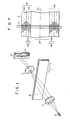
- a code plate 8 mounted to a displacement table or the like (not shown) is irradiated with light emitted from a light source 6 through an illumination lens 7, and the transmitted image is formed on a sensor array 11 of a line sensor 10 by a projection lens 9 to obtain an image.
- T line sensor 10 comprises the sensor array 11 having sensor array elements of independent sensitivities arranged in an array, and it outputs signals corresponding to the image in synchronism with clock pulses.
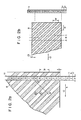
- Figs. 2(a) and 2(b) show the detailed arrangement of the code plate 8 and the sensor array 11 used in Fig. 1.
- a regular lattice i.e.
- this electric signal T(p,q) may be expressed by the following equation: where: a is a constant of photoelectric conversion, and q is a dimensionless term related to the relative displacement of the regular lattice and the line sensor.
- FIG. 3(a) shows the relationship between output b at every other element from the third element (output at the odd-number elements) of the sensor array 11 with an output a at every other element from the fourth element (output of even-numbered elements) when the relative positions of the code plate 8 and the sensor array 11 is as shown at A of Fig. 2(b).
- Fig. 3(b) shows the condition when the position of the sensor array 11 with repeat to the code plate 8 is shifted to the right by 1/22-W in Fig. 2(b). It is seen from this figure that the intersection of the output a with the output b is shifted by one element on the sensor array 11.
- the 1/2 period of the code plate 8 that is, W/2 may be interpolated with sufficient resolution when taking the position of the intersection alone into consideration.
- One period of the code plate 8 may also be interpolated with sufficient resolution by taking into consideration the position of the intersection and the phase conditions of the output of the odd-numbered elements and the output of even-numbered elements.
- the present invention is advantageous in that the detection sensitivity for-displacement may be arbitrarily set by changing the angle of inclination within the range wherein the contrast of the output waveform is sufficient.
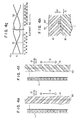
- a track 14 with inclined slits is arranged with another track 15 having slits which are symmetrical with the slits of the track 14.
- Reference numeral 11 denotes the corresponding sensor array.
- the intersections of the output of the sensor array 11 with the lattice pattern of the track 14 and the output of the sensor array 11 with the lattice pattern of the track 15 are shifted in opposite directions on the sensor array according to the distance of displacement. This is shown in Fig. 4(c).
- the Y-axis represents the position of the intersection on the sensor array
- the X-axis represents the distance of displacement in the direction of arrow 12 in Fig. 4(a).
- the loci of the intersections of the track 14 of Fig. 4(a) are shown in the upper half
- the loci of the intersections of the track 15 of Fig. 4(a) are shown in the lower half.
- Fig. 4(d) shows the loci of the intersections when the relative displacement is made in the direction of arrow 13 of Fig. 4(a); the loci are shown in the same manner as in Fig. 4(c).
- the displacement which is half the period of the white and black lattice patterns is 1 period when only the intersections of the even-numbered output and the odd-numbered output of the sensor array are considered.
- the displacement corresponding to the period W of the lattice is 1 period.
- the displacement in the direction of arrow 12 may be separated and detected as the distance between the intersections on the sensor array by the inclined lattice pattern tracks 14 and 15, and the displacement in the direction of arrow 13 may be separated and detected as the displacement of the midpoint between the intersections.
- This arrangement is further advantageous in that the detection sensitivity for detection of displacement in the direction of arrow 12 may be doubled.
- Fig. 4(b) shows another embodiment wherein a track 16 having white and black lattice patterns along the direction perpendicular to the longitudinal direction of the sensor array 11 is attached to the above-described inclined pattern track 14 in such a manner that a vernier relationship is established therebetween.
- a track 16 having white and black lattice patterns along the direction perpendicular to the longitudinal direction of the sensor array 11 is attached to the above-described inclined pattern track 14 in such a manner that a vernier relationship is established therebetween.
- relative displacements in both directions indicated by arrows 12 and 13 may be separated by checking the displacement of the intersection with the track 14 and the displacement of the intersection with the track 16.
- Figs. 4(e) to 4(h) the position of the sensor array with respect to the inclined lattice patterns of the tracks 14 and 15 is at a position 50 shown in this figure. If the relative positions of the track 14 and the sensor array 11 are as shown in Fig. 4(e) and the relative positions of the track 15 and the sensor array 11 are as shown in Fig. 4(f), the output of the sensor array 11 obtained by the vernier relationship at this instant becomes as shown in Fig. 4(g), and intersections 51 and 52 appear on an element 8 and an element 25 of the sensor array, respectively.
- the displacement in the direction of arrow 12 is assumed to be 2 pm and the displacement in the direction of arrow 13 is assumed to be 3 ⁇ m.
- the code plate moves 3 pm in the O direction of the arrow 13, the intersection 51 moves to an element 5, the code plate moves 2 pm in the O direction of the arrow 13, and the intersection 51 thus also moves in the O direction to an element 3.
- the intersection 52 moves to an element 22.
- the intersection 52 moves from the element 22 in the ⁇ direction to an element 24.
- the two-dimensional displacements in the directions of the arrows 12 and 13 may be measured by detecting the positions of intersections obtained with the tracks 14 and 15.
- the displacement in the direction indicated by 12 since the intersection 51 moves from the element 8 to the element 3 and the intersection 52 moves from the element 25 to the element 24 upon relative displacement of the sensor array and the lattice patterns, the displacement in the direction indicated by 12 may be obtained as: and the displacement in the direction indicated by 13 may be obtained as:
- the light transmitted through the code plate is detected by the line sensor.
- the lattice patterns on the code plate need not be binary data of white and black patterns but may be data of continuously gradating transmittance or reflectance. It, therefore, suffices that the lattice patterns which periodically change in transmittance or reflectance be formed on the code plate, establishing a vernier relationship between the period of such change and the corresponding elements of the line sensor.
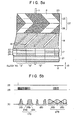
- Fig. 5(a) shows patterns of a code plate for an encoder of high precision and resolution wherein the code plate 8 is divided into a plurality of blocks, the number of each block is read with the address track 17, inside each block is interpolated by the fine reading patterns 19, and inside this fine reading pattern 19 is further interpolated by an inclined lattice 20.
- the patterns of the code plate 8 comprise, as shown in the figure, a reference track 21, an address track 17, a fine track 18, and an inclined lattice track 27 and are related to the sensor array 11 as shown in the figure.
- the reference track 21 shows the reference position of the entire patterns, designates the element of the sensor array for the purpose of reading the address, and indicates the reference position of the fine reading patterns 19.
- the address track 17 has a plurality of further divided tracks 22, 23 and 24 and gray codes are arranged in these further divided tracks for each block divided in the direction indicated by 12.
- the fine reading track 18 includes patterns which vary in the perpendicular direction when the code plate 8 and the sensor array 11 move relative to each other in the direction indicated by 12. These patterns are slightly longer than each block and are capable of distinguishing adjacent blocks. Although these patterns may be distinguished by thickness as in the figure, they may alternatively be distinguished by the number or transmittance.
- the inclined lattice track 27 has patterns shown in Fig. 4(a) and function as has been described hereinbefore.
- the pitch of the sensor array is 10 11m
- the vernier relationship between the sensor array and the inclined lattice patterns is 10: 11.
- the pitch of the inclined lattice patterns of the sensor array becomes 22 ⁇ m, and the position of the intersection of the output of the sensor array moves by a distance corresponding to one element of the sensor array upon a relative displacement of I pm.
- the interpolation within the unit of one element of the sensor array may be accomplished by detecting the positions of the intersections of the sensor array outputs obtained with the inclined lattice patterns by, for example, approximating the outputs of the odd- and even-numbered elements with the respective frequencies and calculating their intersections.
- the displacement in the direction indicated by 13 may similarly be detected with high precision by detecting the position of the reference track 21 projected on the sensor array and also detecting the midpoint of the intersections of the sensor array outputs with the inclined lattice patterns 25 and 26.
- Fig. 5(b) shows the input and output signals of the line sensor according to the arrangement shown in Fig. 5(a) wherein reference numeral 28 denotes a start pulse, 29 denotes a clock pulse, and 30 denotes an output signal proportional to the intensity of light.
- Fig. 6 is an overall block diagram of an encoder according to the present invention. The mode of operation of this encoder will now be described with reference to Figs. 5 and 6.
- the code plate 8 mounted to a moving object 31 such as a table of a machine tool or the like is illuminated by the light source 6 through the illumination lens 7, and an image of the transmitted pattern is formed on the line sensor 10 by the projection lens 9.
- the line sensor 10 starts scanning, and supplies an output signal 35 to an amplifier 36 in synchronism with a clock pulse 34 output from the same pulse generator 32.
- the signals passed through the amplifier 36 are supplied to a sample and hold circuit 37 which holds the peak value of the output of each element as an analog voltage which is converted into a digital signal by an analog-to- digital converter 38.
- a digital memory 39 sequentially stores the AID converted outputs of the line sensor 10. If the digital..memory 39 comprises a random access memory, the outputs of the line sensor are sequentially stored from the zero address of the memory by designating the addresses of the memory by the output of a counter 40 which counts the clock pulses output in synchronism with the outputs of the line sensor. The addresses of the memory and the bit numbers of the line sensor thus establish a one-to-one correspondence. The counter 40 must be reset in advance by the scanning start pulse 33 or a scanning terminating pulse 41.
- a signal processing circuit 43 comprises, for example, a microprocessor. In response to the scanning terminating pulse 41 of the line sensor, the signal processing circuit 43 transfers the line sensor output data temporarily stored in the digital memory 39 to a data memory 42 under its control and starts processing the data. The operation of the signal processing circuit 43 includes the following:
- This correction is performed between the fine reading value and the address.
- correction must be performed between the interpolated value obtained with the inclined lattice pattern and the fine reading.
- the correction may be easily performed.
- the correction between the interpolated value obtained with the inclined lattice patterns with the fine reading obtained with the fine reading patterns may be easily performed by making the range of the interpolated value wider than the resolutions of the fine reading obtained with the fine reading patterns.
- the midpoint of a segment connecting points at which the leading and trailing edges of the output are half the peak value may be obtained.
- the output waveform may be approximated by a poly- nominal and the maximum value may be obtained.
- the central positions may be detected with resolution significantly smaller than the pitch of the sensor array.
- the change in the optical system for projecting the pattern of the code plate on the sensor array for example, a change in the magnification of the projecting lens as designed by 9 in Fig. 6 is included in the measurement as errors.
- a change in the magnification of the projecting lens as designed by 9 in Fig. 6 is included in the measurement as errors.
- the pattern designed for a magnification of 1:1 is projected on the sensor array with a different magnification due to errors introduced by the focal distance of the projecting lens or errors in setting the code plate, the projecting lens, and the sensor array, errors are included in the reading. For this reason, high precision may not be achieved unless control of the focal distance of the projecting optical system and the adjustment during assembly are performed under strict control.
- Fig. 7 shows an example of patterns of the code plate according to a further embodiment of the present invention which is modified to solve these problems and which realizes high precision without requiring such strict control of magnification.
- another inclined lattice track 46 for correction of magnification of similar structure is arranged symmetrically with the inclined lattice track 27 already described above about an optical axis 45 (or optical center) of the projecting optical system.
- the reference track, the address track and the fine reading track are arranged in the same manner as in Fig. 5(a), these parts being omitted for the sake of simplicity.
- the patterns of the code plate projected on the sensor array are displaced symmetrically about the optical axis.
- the positions of the intersections of the sensor array outputs move to the direction indicated by 49 the same distance, respectively.
- the patterns are projected on an enlarged scale, the intersections of the sensor array move in the direction indicated by 48 and the distance of their movement is proportional to the rate of change of the projecting magnification.
- the midpoint of the intersections of the sensor array outputs obtained with the inclined lattice pattern 25 and the inclined lattice pattern 26 is detected as the projected position of the inclined lattice track 27 on the sensor array.
- the projected position of the inclined lattice track 46 on the sensor array is detected. Then, a deviation from a reference set distance (e.g., when the projecting magnification is 1:1) indicates the change of the projecting magnification. Therefore, an encoder may be manufactured which is not affected by the change in the projecting magnification by correcting the reading according to the deviation thus obtained.
- a reference set distance e.g., when the projecting magnification is 1:1
- the range of correction may be widened by arranging the reference track and the fine reading track symmetrically about the optical axis of the projecting optical system.
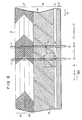
- Fig. 8 shows an encoder for incrementally measuring lengths or angles according to a further embodiment of the present invention.
- a plurality of blocks N-1, N, N+1,... are formed in the code plate 8
- each block 103 (N-1) has the reference track 21, the fine reading track 18, and the inclined lattice track 27 which have been described hereinbefore.
- Fine reading patterns 19 of the fine reading track 18 may comprise lines of the same thickness unlike in the case of the embodiments described above.
- the sensor array 11 is arranged in the direction perpendicular to the direction of normal displacement of the code plate 8 relative to the sensor array 11.
- the driver for driving this encoder is of the same construction as that of the embodiment described above.
- the measuring procedure is as follows. The measuring procedure described below is for measuring the displacement in the direction indicated by 12.
- a particular sensor array element located at a certain distance from the central position of the reference track is used as a sensor element for incremental counting.
- Block counting is performed by counting the fine reading patterns with this sensor element.
- a detecting element separate from the elements of the sensor array may be incorporated for counting the fine reading patterns for the purpose of counting the blocks.
- a rotary encoder may also be realized by utilizing, for example, a ringshaped code plate.
- the fine reading patterns and the inclined lattice patterns may be linear.
- the interpolation precision that is, the minimum measuring precision of an encoder of the present invention may be varied by changing projecting magnification of the projecting lens 9 shown in Fig. 2.
- the relative positions of the code plate and the line sensor are measured in the above embodiments.
- the patterns of the code plate may be reflected with a reflector or the like while holding stationary the code plate and the line sensor, and the displacement of the reflector may be measured.
- the reflected image may be used instead of the transmitted image of the code plate.
- the reading with the unit of the pitch of the sensor array may be performed only with the address track without utilizing the fine reading patterns.
- the number of further divided tracks within the address track may increase depending upon the length of the code plate or the angular divisor thereof, this may not necessarily result in a disadvantage since line sensors which have sufficient number of elements and which are inexpensive are readily available today.
Applications Claiming Priority (2)
| Application Number | Priority Date | Filing Date | Title |
|---|---|---|---|
| JP8169780A JPS576994A (en) | 1980-06-17 | 1980-06-17 | Coding board for encoder |
| JP81697/80 | 1980-06-17 |
Publications (3)
| Publication Number | Publication Date |
|---|---|
| EP0042179A2 EP0042179A2 (en) | 1981-12-23 |
| EP0042179A3 EP0042179A3 (en) | 1983-06-22 |
| EP0042179B1 true EP0042179B1 (en) | 1986-05-07 |
Family
ID=13753558
Family Applications (1)
| Application Number | Title | Priority Date | Filing Date |
|---|---|---|---|
| EP81104660A Expired EP0042179B1 (en) | 1980-06-17 | 1981-06-16 | Encoder |
Country Status (4)
| Country | Link |
|---|---|
| US (1) | US4465373A (ja) |
| EP (1) | EP0042179B1 (ja) |
| JP (1) | JPS576994A (ja) |
| DE (1) | DE3174549D1 (ja) |
Cited By (1)
| Publication number | Priority date | Publication date | Assignee | Title |
|---|---|---|---|---|
| DE102006010161A1 (de) * | 2006-02-28 | 2007-08-30 | Dr. Johannes Heidenhain Gmbh | Codestruktur für eine Positionsmesseinrichtung und Positionsmesseinrichtung mit einer solchen Codestruktur |
Families Citing this family (38)
| Publication number | Priority date | Publication date | Assignee | Title |
|---|---|---|---|---|
| JPS5829093A (ja) * | 1981-08-13 | 1983-02-21 | 株式会社トプコン | アブソリユ−トエンコ−ダ |
| JPS58150819A (ja) * | 1982-03-03 | 1983-09-07 | Mitsubishi Electric Corp | 光学式エンコ−ダ |
| US4553035A (en) * | 1983-08-30 | 1985-11-12 | Mylex Corporation | Data acquisition control method and system for a hand held reader |
| GB2179515B (en) * | 1985-08-22 | 1989-08-02 | Muirhead Vactric Components | Interpolation method and application thereof to encoders |
| US4720699A (en) * | 1985-10-28 | 1988-01-19 | Smith Ronald H | Optical encoder using line array detectors |
| DE3542514A1 (de) * | 1985-12-02 | 1987-06-04 | Zeiss Carl Fa | Wegmesseinrichtung |
| US5214426A (en) * | 1988-07-12 | 1993-05-25 | Furuno Electric Company, Limited | Rotary encoder having absolute angle patterns and relative angle patterns |
| US4984287A (en) * | 1988-11-15 | 1991-01-08 | Msc Technologies, Inc. | Method for orienting a dual mouse optical scanner |
| US4942621A (en) * | 1988-11-15 | 1990-07-17 | Msc Technologies, Inc. | Method for mapping scanned pixel data |
| US5237391A (en) * | 1988-11-23 | 1993-08-17 | The Boeing Company | Multitrack multilevel sensing system |
| US5069547A (en) * | 1988-11-23 | 1991-12-03 | The Boeing Company | Multitrack multilevel sensing system with error detecting |
| US5017776A (en) * | 1989-03-10 | 1991-05-21 | Hewlett-Packard Company | Apparatus for and methods of optical encoding having spiral shaped light modulator |
| DE4014479A1 (de) * | 1989-05-11 | 1990-11-15 | Volkswagen Ag | Einrichtung zur ermittlung der bewegungsstrecke zwischen zwei relativbewegungen ausfuehrenden teilen |
| US5105296A (en) * | 1989-11-20 | 1992-04-14 | Dainippon Screen Mfg. Co., Ltd. | Method and apparatus for detecting beam spot shape |
| US5254919A (en) * | 1991-03-22 | 1993-10-19 | Eastman Kodak Company | Encoder system using linear array sensor for high resolution |
| US5699058A (en) * | 1994-03-17 | 1997-12-16 | Copal Company Limited | Absolute encoder generating phase-shifted triangular waveforms to produce multi-bit signals |
| US6327791B1 (en) | 1999-06-09 | 2001-12-11 | The Government Of The United States As Represented By The Secretary Of Commerce | Chain code position detector |
| WO2000077472A1 (en) * | 1999-06-16 | 2000-12-21 | Snorkel International, Inc. | Chain code position detector |
| US6922907B2 (en) | 2001-04-05 | 2005-08-02 | Anton Rodi | Measuring system for recording absolute angular or position values |
| DE10117193B4 (de) * | 2001-04-05 | 2013-04-04 | Anton Rodi | Messsystem zur Absolutwerterfassung von Winkeln oder Wegen |
| US6912797B2 (en) * | 2001-04-05 | 2005-07-05 | Anton Rodi | Measuring system for recording absolute angular or position values |
| US6456244B1 (en) | 2001-07-23 | 2002-09-24 | Harris Corporation | Phased array antenna using aperiodic lattice formed of aperiodic subarray lattices |
| US6842157B2 (en) * | 2001-07-23 | 2005-01-11 | Harris Corporation | Antenna arrays formed of spiral sub-array lattices |
| US6897829B2 (en) * | 2001-07-23 | 2005-05-24 | Harris Corporation | Phased array antenna providing gradual changes in beam steering and beam reconfiguration and related methods |
| US7069120B1 (en) * | 2003-10-22 | 2006-06-27 | Rockwell Collins, Inc. | Position sensing system |
| US7568727B2 (en) * | 2005-04-06 | 2009-08-04 | Ford Global Technologies, Llc | Airbag deployment monitoring system |
| DE102005032869A1 (de) * | 2005-07-14 | 2007-01-25 | Leopold Kostal Gmbh & Co. Kg | Verfahren zum Bestimmen der absoluten Winkelstellung des Lenkrades eines Kraftfahrzeugs |
| US8182065B2 (en) * | 2005-07-29 | 2012-05-22 | Hewlett-Packard Development Company, L.P. | Apparatus and methods for compensation of thermal and hydroscopic expansion effects in a low cost motion control system |
| EP1790953A1 (de) * | 2005-11-04 | 2007-05-30 | Leica Geosystems AG | Optoelektrische Winkelmesseinrichtung |
| US7399956B2 (en) * | 2005-11-28 | 2008-07-15 | Avago Technologies Ecbuip Pte Ltd | Optical encoder with sinusoidal photodetector output signal |
| US7615737B2 (en) * | 2007-05-08 | 2009-11-10 | The Boeing Company | High precision compact rotation angle absolute encoder |
| JP2010256081A (ja) * | 2009-04-22 | 2010-11-11 | Fujifilm Corp | 光学式位置検出器及び光学装置 |
| US10357714B2 (en) | 2009-10-27 | 2019-07-23 | Harmonix Music Systems, Inc. | Gesture-based user interface for navigating a menu |
| JP5574899B2 (ja) * | 2010-09-24 | 2014-08-20 | キヤノン株式会社 | ロータリーエンコーダ及びこれを備えた光学機器 |
| EP3064902B1 (de) * | 2015-03-06 | 2017-11-01 | Hexagon Technology Center GmbH | System zur bestimmung von positionen |
| EP3121565B1 (de) | 2015-07-24 | 2018-09-12 | Hexagon Technology Center GmbH | Absolutpositionsbestimmung |
| US10989566B2 (en) | 2018-04-09 | 2021-04-27 | Infineon Technologies Ag | Magnetic sensor system for measuring linear position |
| TWI716246B (zh) * | 2019-12-31 | 2021-01-11 | 財團法人工業技術研究院 | 光學編碼器 |
Citations (1)
| Publication number | Priority date | Publication date | Assignee | Title |
|---|---|---|---|---|
| EP0013799A2 (en) * | 1978-12-19 | 1980-08-06 | Kabushiki Kaisha Toshiba | Encoder for length or angle measuring devices with high accuracy |
Family Cites Families (11)
| Publication number | Priority date | Publication date | Assignee | Title |
|---|---|---|---|---|
| DE1282988B (de) * | 1965-05-28 | 1968-11-14 | Zeiss Carl Fa | Einrichtung zum Messen von Lageaenderungen zweier zueinander beweglicher Teile unterVerwendung einer inkohaerenten Strahlung |
| GB1169698A (en) * | 1965-12-02 | 1969-11-05 | Nat Res Dev | Improvements in or relating to Positional Displacement Transducer Arrangements |
| SE324463B (ja) * | 1968-03-27 | 1970-06-01 | Aga Ab | |
| GB1192513A (en) * | 1968-05-02 | 1970-05-20 | Feinmass Dresden Veb | Improvements in and relating to Linear Measurement Scales |
| US3648276A (en) * | 1969-12-11 | 1972-03-07 | Warner Swasey Co | Segmented scale |
| US3708681A (en) * | 1971-04-01 | 1973-01-02 | Dynamics Res Corp | Position and velocity sensor |
| US3748043A (en) * | 1972-03-20 | 1973-07-24 | Bendix Corp | Photoelectric interpolating arrangement for reading displacements of divided scales |
| FR2271540A2 (en) * | 1974-02-05 | 1975-12-12 | Boudier Pierre | Electronic vernier device with slotted disc - has non-radial slots and two phototransistors on radius to give incremental signals |
| JPS5166856A (en) * | 1974-12-06 | 1976-06-09 | Hitachi Ltd | Fukusukono pataannosotaitekiheniryosokuteihoho oyobi sonosochi |
| DE2758854C2 (de) * | 1977-12-30 | 1979-09-27 | Dr. Johannes Heidenhain Gmbh, 8225 Traunreut | Vorrichtung zum Messen der Verschiebung und/oder der Geschwindigkeit eines mit einem optischen Streifenmuster verbundenen Körpers |
| US4180703A (en) * | 1978-06-28 | 1979-12-25 | International Business Machines Corporation | Bi-directional, self imaging grating detection apparatus |
-
1980
- 1980-06-17 JP JP8169780A patent/JPS576994A/ja active Granted
-
1981
- 1981-06-15 US US06/273,772 patent/US4465373A/en not_active Expired - Lifetime
- 1981-06-16 DE DE8181104660T patent/DE3174549D1/de not_active Expired
- 1981-06-16 EP EP81104660A patent/EP0042179B1/en not_active Expired
Patent Citations (1)
| Publication number | Priority date | Publication date | Assignee | Title |
|---|---|---|---|---|
| EP0013799A2 (en) * | 1978-12-19 | 1980-08-06 | Kabushiki Kaisha Toshiba | Encoder for length or angle measuring devices with high accuracy |
Cited By (2)
| Publication number | Priority date | Publication date | Assignee | Title |
|---|---|---|---|---|
| DE102006010161A1 (de) * | 2006-02-28 | 2007-08-30 | Dr. Johannes Heidenhain Gmbh | Codestruktur für eine Positionsmesseinrichtung und Positionsmesseinrichtung mit einer solchen Codestruktur |
| DE102006010161B4 (de) * | 2006-02-28 | 2010-04-08 | Dr. Johannes Heidenhain Gmbh | Codestruktur für eine Positionsmesseinrichtung und Positionsmesseinrichtung mit einer solchen Codestruktur |
Also Published As
| Publication number | Publication date |
|---|---|
| EP0042179A3 (en) | 1983-06-22 |
| JPS576994A (en) | 1982-01-13 |
| JPS6331722B2 (ja) | 1988-06-27 |
| DE3174549D1 (en) | 1986-06-12 |
| EP0042179A2 (en) | 1981-12-23 |
| US4465373A (en) | 1984-08-14 |
Similar Documents
| Publication | Publication Date | Title |
|---|---|---|
| EP0042179B1 (en) | Encoder | |
| EP0039082B1 (en) | Method and apparatus for measuring the displacement between a code plate and a sensor array | |
| EP0042178B1 (en) | Absolute encoder | |
| US4518859A (en) | Angle measuring device with line sensor | |
| EP0100243B1 (en) | Position sensor | |
| EP0013799B1 (en) | Encoder for length or angle measuring devices with high accuracy | |
| JP2546823B2 (ja) | 位置検出方法および装置 | |
| US5068529A (en) | Absolute position detection encoder | |
| EP0503716B1 (en) | Measuring device for determining an absolute position of a movable element and scale graduation element suitable for use in such a measuring device | |
| US5235181A (en) | Absolute position detector for an apparatus for measuring linear angular values | |
| US4421980A (en) | Position encoder with closed-ring diode array | |
| EP0072549B1 (en) | Absolute encoder | |
| US3285123A (en) | Scale reading apparatus | |
| US4492861A (en) | Arrangement for detecting the position of an index mark relative to a graduation | |
| JPS61182522A (ja) | リニアスケ−ル測定装置 | |
| JPS63290916A (ja) | 光学式リニアスケ−ル装置 | |
| JPS63117214A (ja) | 変位測定装置 | |
| JP2732488B2 (ja) | 測長または測角装置 | |
| JPH0141925B2 (ja) | ||
| JPH0342611B2 (ja) | ||
| JPH0143243B2 (ja) | ||
| JPH0157291B2 (ja) | ||
| WO1991010288A2 (en) | Position sensor | |
| JPS6343683B2 (ja) | ||
| JPH0335111A (ja) | 絶対位置検出装置 |
Legal Events
| Date | Code | Title | Description |
|---|---|---|---|
| PUAI | Public reference made under article 153(3) epc to a published international application that has entered the european phase |
Free format text: ORIGINAL CODE: 0009012 |
|
| 17P | Request for examination filed |
Effective date: 19810716 |
|
| AK | Designated contracting states |
Designated state(s): CH DE FR GB LI SE |
|
| PUAL | Search report despatched |
Free format text: ORIGINAL CODE: 0009013 |
|
| RHK1 | Main classification (correction) |
Ipc: G01D 5/245 |
|
| AK | Designated contracting states |
Designated state(s): CH DE FR GB LI SE |
|
| GRAA | (expected) grant |
Free format text: ORIGINAL CODE: 0009210 |
|
| AK | Designated contracting states |
Kind code of ref document: B1 Designated state(s): CH DE FR GB LI SE |
|
| REF | Corresponds to: |
Ref document number: 3174549 Country of ref document: DE Date of ref document: 19860612 |
|
| ET | Fr: translation filed | ||
| PLBE | No opposition filed within time limit |
Free format text: ORIGINAL CODE: 0009261 |
|
| STAA | Information on the status of an ep patent application or granted ep patent |
Free format text: STATUS: NO OPPOSITION FILED WITHIN TIME LIMIT |
|
| 26N | No opposition filed | ||
| REG | Reference to a national code |
Ref country code: CH Ref legal event code: PFA Free format text: KABUSHIKI KAISHA TOPCON |
|
| REG | Reference to a national code |
Ref country code: FR Ref legal event code: CD |
|
| PGFP | Annual fee paid to national office [announced via postgrant information from national office to epo] |
Ref country code: FR Payment date: 19920521 Year of fee payment: 12 |
|
| PGFP | Annual fee paid to national office [announced via postgrant information from national office to epo] |
Ref country code: GB Payment date: 19920605 Year of fee payment: 12 |
|
| PGFP | Annual fee paid to national office [announced via postgrant information from national office to epo] |
Ref country code: SE Payment date: 19920617 Year of fee payment: 12 |
|
| PG25 | Lapsed in a contracting state [announced via postgrant information from national office to epo] |
Ref country code: GB Effective date: 19930616 |
|
| PG25 | Lapsed in a contracting state [announced via postgrant information from national office to epo] |
Ref country code: SE Effective date: 19930617 |
|
| GBPC | Gb: european patent ceased through non-payment of renewal fee |
Effective date: 19930616 |
|
| PG25 | Lapsed in a contracting state [announced via postgrant information from national office to epo] |
Ref country code: FR Effective date: 19940228 |
|
| REG | Reference to a national code |
Ref country code: FR Ref legal event code: ST |
|
| EUG | Se: european patent has lapsed |
Ref document number: 81104660.6 Effective date: 19940110 |
|
| PGFP | Annual fee paid to national office [announced via postgrant information from national office to epo] |
Ref country code: CH Payment date: 20000518 Year of fee payment: 20 |
|
| PGFP | Annual fee paid to national office [announced via postgrant information from national office to epo] |
Ref country code: DE Payment date: 20000726 Year of fee payment: 20 |
|
| PG25 | Lapsed in a contracting state [announced via postgrant information from national office to epo] |
Ref country code: LI Free format text: LAPSE BECAUSE OF EXPIRATION OF PROTECTION Effective date: 20010615 Ref country code: CH Free format text: LAPSE BECAUSE OF EXPIRATION OF PROTECTION Effective date: 20010615 |
|
| REG | Reference to a national code |
Ref country code: CH Ref legal event code: PL |