EP0072549B1 - Absolute encoder - Google Patents
Absolute encoder Download PDFInfo
- Publication number
- EP0072549B1 EP0072549B1 EP82107383A EP82107383A EP0072549B1 EP 0072549 B1 EP0072549 B1 EP 0072549B1 EP 82107383 A EP82107383 A EP 82107383A EP 82107383 A EP82107383 A EP 82107383A EP 0072549 B1 EP0072549 B1 EP 0072549B1
- Authority
- EP
- European Patent Office
- Prior art keywords
- track
- patterns
- blocks
- sensor
- reading
- Prior art date
- Legal status (The legal status is an assumption and is not a legal conclusion. Google has not performed a legal analysis and makes no representation as to the accuracy of the status listed.)
- Expired
Links
- 230000003287 optical effect Effects 0.000 claims description 22
- 238000003384 imaging method Methods 0.000 description 5
- 238000000034 method Methods 0.000 description 5
- 238000012545 processing Methods 0.000 description 4
- 238000006073 displacement reaction Methods 0.000 description 3
- 238000010586 diagram Methods 0.000 description 2
- 238000005516 engineering process Methods 0.000 description 2
- 239000000835 fiber Substances 0.000 description 2
- 230000006870 function Effects 0.000 description 2
- 238000005259 measurement Methods 0.000 description 2
- 238000012935 Averaging Methods 0.000 description 1
- 125000004122 cyclic group Chemical group 0.000 description 1
- 238000001514 detection method Methods 0.000 description 1
- 238000005286 illumination Methods 0.000 description 1
- 230000002093 peripheral effect Effects 0.000 description 1
- 230000001373 regressive effect Effects 0.000 description 1
- 230000004044 response Effects 0.000 description 1
- 230000035945 sensitivity Effects 0.000 description 1
- 238000012546 transfer Methods 0.000 description 1
- 230000004304 visual acuity Effects 0.000 description 1
Images


Classifications
-
- G—PHYSICS
- G01—MEASURING; TESTING
- G01D—MEASURING NOT SPECIALLY ADAPTED FOR A SPECIFIC VARIABLE; ARRANGEMENTS FOR MEASURING TWO OR MORE VARIABLES NOT COVERED IN A SINGLE OTHER SUBCLASS; TARIFF METERING APPARATUS; MEASURING OR TESTING NOT OTHERWISE PROVIDED FOR
- G01D5/00—Mechanical means for transferring the output of a sensing member; Means for converting the output of a sensing member to another variable where the form or nature of the sensing member does not constrain the means for converting; Transducers not specially adapted for a specific variable
- G01D5/26—Mechanical means for transferring the output of a sensing member; Means for converting the output of a sensing member to another variable where the form or nature of the sensing member does not constrain the means for converting; Transducers not specially adapted for a specific variable characterised by optical transfer means, i.e. using infrared, visible, or ultraviolet light
- G01D5/32—Mechanical means for transferring the output of a sensing member; Means for converting the output of a sensing member to another variable where the form or nature of the sensing member does not constrain the means for converting; Transducers not specially adapted for a specific variable characterised by optical transfer means, i.e. using infrared, visible, or ultraviolet light with attenuation or whole or partial obturation of beams of light
- G01D5/34—Mechanical means for transferring the output of a sensing member; Means for converting the output of a sensing member to another variable where the form or nature of the sensing member does not constrain the means for converting; Transducers not specially adapted for a specific variable characterised by optical transfer means, i.e. using infrared, visible, or ultraviolet light with attenuation or whole or partial obturation of beams of light the beams of light being detected by photocells
- G01D5/347—Mechanical means for transferring the output of a sensing member; Means for converting the output of a sensing member to another variable where the form or nature of the sensing member does not constrain the means for converting; Transducers not specially adapted for a specific variable characterised by optical transfer means, i.e. using infrared, visible, or ultraviolet light with attenuation or whole or partial obturation of beams of light the beams of light being detected by photocells using displacement encoding scales
- G01D5/34776—Absolute encoders with analogue or digital scales
-
- H—ELECTRICITY
- H03—ELECTRONIC CIRCUITRY
- H03M—CODING; DECODING; CODE CONVERSION IN GENERAL
- H03M1/00—Analogue/digital conversion; Digital/analogue conversion
- H03M1/12—Analogue/digital converters
- H03M1/22—Analogue/digital converters pattern-reading type
- H03M1/24—Analogue/digital converters pattern-reading type using relatively movable reader and disc or strip
- H03M1/28—Analogue/digital converters pattern-reading type using relatively movable reader and disc or strip with non-weighted coding
- H03M1/30—Analogue/digital converters pattern-reading type using relatively movable reader and disc or strip with non-weighted coding incremental
- H03M1/308—Analogue/digital converters pattern-reading type using relatively movable reader and disc or strip with non-weighted coding incremental with additional pattern means for determining the absolute position, e.g. reference marks
Definitions
- the present invention relates to encoders for digitally reading a linear or angular length. More particularly, the present invention pertains to absolute encoders which include a code carrying medium having coded patterns such as binary codes and adapted to be advanced in one direction so that the coded patterns are read by photoelectrical means.
- Such absolute encoders are considered as advantageous over incremental type encoders in that, even when there is an interruption of electric power supply or an erroneous operation due to electrical noises, a correct read out operation can be recovered as soon as a normal condition is restored.
- conventional encoders have disadvantages in that a large number of light sources and photoelectric elements are required for read out operations and that the resolving power is limited by the coded pattern forming technology and the sensitivity of the photoelectric elements.
- the encoder includes a code carrying medium adapted to be advanced in one direction and having a plurality of blocks arranged in series in the direction of advancement.
- the code carrying medium has a mark pattern comprised of a character pattern and a reference position mark, a code bar pattern, and an address pattern including an address bar specific to the block.
- a line sensor including a plurality of photoelectric elements arranged in series is used for cooperation with the code carrying medium so that the medium is advanced with respect to the line sensor whereby the patterns on the medium are read by the sensor.
- the feature of the encoder as proposed by the Japanese patent application 53-155815 is that the pitch of the code bars in the code bar pattern is slightly different from the pitch of the photoelectric elements in the line sensor. For example, a length of the code carrying medium corresponding to ten code bars may correspond to eleven photoelectric elements.
- detection is at first made of a specific photoelectric element which is receiving the projection of the reference position mark. Then, the address of the block concerned is interpreted by detecting the address bar in the address pattern. Operation is then made to calculate the distance between a predetermined one of the photoelectric elements and the specific photoelectric element receiving the projection of the reference position mark to thereby obtain a rough value of the relative displacement of the code carrying medium with respect to the line sensor.
- a further fine read out is made under the principle of a vernier scale. The procedures for performing such fine read out are fully described in the aforementioned Japanese patent application and the corresponding U.S. and European patent applications.
- the proposed encoder is advantageous in that the coded patterns can be provided on a single code track extending in the direction of movement of the code carrying medium and that a high precision read out can be made by utilizing the principle of vernier scale.
- the encoder is however found disadvantageous in that it is difficult to increase the read out speed.
- the read out is made mostly statically, however, there are applications in which dynamic read out is desired. In fact, there are applications which require very fast read out and the proposed encoder is not suitable for such applications.
- DE-A-2 811 807 discloses a digital-absolute angle encoder having the vernier principle.
- the code disc carries two concentric codes, the latter being the vernier graduation.
- US-A-3 458 709 shows an angle encoder having a rotatable code disc and using a theodolite optical system.
- this object can be accomplished by an encoder according to claim 1.
- the coded bar patterns on the code carrying medium may be projected on the photoelectrical sensor means with 1:1 magnification.
- the actual pitch of the coded bar patterns must be slightly different from the actual pitch of the sensing elements of the sensor means to produce the vernier relationship.
- the actual pitch of the coded bar patterns may be the same as that of the sensing elements but the former may be slightly changed by suitable optical means when the patterns are projected on the sensor means.
- the second blocks in said second track are arranged with a pitch larger than that of said first blocks in said first track.
- the code carrying medium may further include at least one reference track for representing a reference position in a direction crossing to said direction of movement of the code carrying medium.
- the medium includes a fine reading track 21 and a rough reading track 22 which are parallel with each other and extending in the lengthwise direction of the medium 8.
- the medium 8 is moved in the direction shown by an arrow 11 in Figure 1.
- the fine reading track 21 is divided into a plurality of blocks 21a which are arranged in series along the length of the track 21.
- In each of the blocks 21a there are formed a mark pattern 12 and a code bar pattern 16.
- the mark pattern 12 includes transparent portion 12a and an opaque portion 12b whereas the code bar pattern 16 includes a series of alternately arranged transparent and opaque bars 16a and 16b of a regular pitch.
- the rough reading track 22 is divided into a plurality of blocks 23 which are arranged in series along the length of the track 22.
- each of the blocks 23 there is formed an address pattern 23a which contains an information of the address of the particular block 23.
- the address pattern 23a is recorded in the direction perpendicular to the direction 11 of movement of the medium 8 as will be described in more detail later.
- Beneath the code carrying medium 8,there is a photoelectrical sensing device 10 comprising line sensors 10A and 10B.
- Each of the line sensors 10A and 10B includes a linear array of photoelectrical elements as well known in the art.
- Figure 2 shows an optical system for reading the patterns on the medium 8 by means of the sensing device 10.
- the optical system includes a light source 6 and a condenser lens 7 for directing the beam of light from the light source 6 to the medium 8.
- the light beam which has passed through the medium 8 is focused by an imaging lens 9 on the sensing device 10 to produce an image of the patterns on the medium 8.
- the linear sensor 10B includes a linear array of photoelectrical sensing elements 15 which are arranged with a regular pitch P.
- Each of the bars 16a and 16b in the code bar pattern 16 has a width W.
- the pitch P of the elements 15 in the line sensor 10B and the width W of each bar 16a or 16b in the code bar pattern 16 are slightly different from each other so as to produce a vernier relationship therebetween.
- the length containing ten code bars 16a and 16b is equal to the length containing eleven photoelectric elements 15 so that one-tenth of the pitch P of the photoelectric element can be detected by the principle of the vernier scale.
- the mark pattern 12 is provided for detecting the particular element or elements 15 on which the pattern 12 is projected and calculating the distance between such element or elements and a predetermined one of the elements which is usually referred to as an "index bit IB" to thereby make it possible to read the relative position of the specific block 21 a with respect to the line sensor 10B by the order of the pitch P of the elements 15.
- the rough reading track 22 is divided into a plurality of sub-tracks 22a through 22e which are arranged in a direction perpendicular to the direction of movement of the medium 8.
- the sub-tracks 22a through 22e are coded in a binary method so as to form the aforementioned address pattern 23a.
- the line sensor 10A is constructed in the same way as the line sensor 10B and arranged with its lengthwise direction coincided with the direction of arrangement of the sub-tracks 22a through 22e.
- Figure 4 shows a modified form of the optical system which may be used with the code carrying medium 8 shown in Figure 1.
- the optical system shown in Figure 4 is intended to make it possible to read the informations by a single linear sensor 10.
- the beam of light from the light source 6 is passed through the condenser lens 7 and then through the code carrying medium 8.
- the portion of the light beam which has passed through the fine reading track 21 is projected through the focusing lens 27 to the sensor 10.
- the portion of the light beam which has passed through the rough reading track 22 is reflected by mirrors 29 and 30 so that the images of the patterns on the track 22 are rotated by 90°.
- the light beam from the mirror 30 is then passed through a focusing lens 28 and reflected by a mirror 31 to be projected on the sensor 10.
- the pattern recorded transversely on the track 22 is projected on the sensor 10 longitudinally along the array of the photoelectric elements in the sensor 10.
- the patterns for fine reading are provided on a track separated from the track where the rough reading patterns are provided. Further, the binary bits constituting the rough reading patterns are arranged in a direction crossing the direction of the relative movement of the code carrying medium 8. It is therefore possible to obtain an increased density of the fine reading patterns and to decrease the length of each recording block.
- the arrangements are thus convenient in reading more than one blocks for the purpose of ensuring accuracy of measurement, because the area of illumination may not necessarily be broadened. Even when the patterns are recorded on arcuate tracks, the reading can be carried out by a linear array of sensing elements without producing any significant error. Further, the reading can be made more rapidly than the previously discussed prior art.
- the rough reading track 22 has two blocks 23 in a length corresponding to one block length in the fine reading track 21.
- This arrangement is advantageous in preventing possible reading errors when the sensor 10A is on the border between two adjacent blocks on the rough reading track 22. Assuming in Figure 1 that the sensor 10A is on the border between the block for the address "0" and the block for the address "1", the address reading will take the value "0" or "1" so that there will be a possibility of producing a large error if the value is simply added to the value of the fine reading. In the arrangement shown in Figure 1, the possibility of such an error can be avoided by the following procedure.
- the sensor 10B includes one hundred elements in the length corresponding to one block length on the fine reading track 8.
- the address value as read by the sensor 10A is an odd number and the value of fine reading is greater than "twenty-five”
- the value "one” is subtracted from the address value, but the value "one” is added when the fine reading is smaller than "twenty-five”.
- the address value is an even number
- the value "two” is subtracted from the address value where the fine reading value is greater than "seventy-five” whereas the address value is adopted as it is where the fine reading value is smaller than "seventy-five”.
- the code carrying medium 8 in accordance with one embodiment of the present invention is placed on a movable member 45 such as a movable table of a machine tool.
- the informations on the medium 8 are read by an optical system including a light source 6, a condenser lens 7 and an imaging lens 9, and a photoelectric sensing device 10.
- the medium 8 carries coded patterns as shown in Figure 1 and the optical system as shown in Figure 2 may be used together with the linear sensors 10A and 10B as shown in Figure 1. Alternatively, the optical system as shown in Figure 4 may be used together with a single linear sensor 10.
- a pulse generator 32 is associated with the sensor 10 to apply thereto a start pulse 33 and a clock pulse 34.
- the sensor 10 start to operate as soon as the start pulse 33 is received from the pulse generator 32 and produces an output 35 in synchronism with the clock pulse 34 from the pulse generator 32.
- the output 35 from the sensor 10 is applied to an amplifier 36 which has an output connected with a sample hold 37.
- the sample hold 37 functions to store as an analogue voltage the peak value of the output of each sensing element of the sensor 10.
- the output of the sample hold 37 is connected with an analogue-digital transducer 38 which converts the analogue voltage signal from the sample hold 37 to a digital value.
- the output of the transducer 38 is connected with a digital memory 39 where the output signals from the sensor 10 are sequentially memorized.
- the digital memory 39 may be of a random access type and a counter 40 may be provided for receiving the clock pulse from the pulse generator 32.
- the output of the counter 40 is applied to the memory 39 to sequentially store the output signals from the sequential elements in the sensor 10 whereby the addresses of the respective ones of the memorized signals can have direct correspondence with the bit numbers of the sensor 10.
- the counter 40 must be reset either by the start pulse 33 or an end pulse 41 which may be applied thereto from the sensor 10.
- a signal processing circuit 43 is provided for receiving the scan end pulse 41 from the sensor 10 and functions to transfer the data in the memory 39 to a data memory 42 when the scan end pulse 41 is received to perform data processing.
- each block 21 a in the fine reading track 21 has a block stop mark 12c at the end thereof, which comprises an opaque portion having a length corresponding to three elements in the sensor 10.
- the code bar pattern 16 includes thirty transparent and opaque bars 16a and 16b.
- Each of the sub-tracks 22a through 22e in the rough reading track 22 has a width corresponding to four elements in the sensor 10.
- the fine reading can be obtained from the value as obtained in the paragraph (1) and the value as obtained in this paragraph by carrying out the following calculation.
- intersection 46 is shifted by a distance equal to 4.98 times the pitch between the elements in the sensor. Since there is a vernier relationship of 10:11 and the pitch between the elements is 10 pm, the fine reading is 4.98 pm.
- the value is then added to the value as obtained by the address code in the paragraph (4) to determine the relative displacement between the code carrying medium 8 and the sensor 10.
- the code carrying medium 8 is in the form of a rotatable disc which is adapted to rotate about an axis 0.
- the disc 8 has a peripheral portion formed with a circular fine reading track 21 and a circular rough reading track 22 both of which have patterns as the tracks 21 and 22 in the previous embodiment have.
- the encoder shown in Figure 7 has a pair of optical systems for reading the patterns in the fine reading track 21 at diametrically opposite positions. Since the eccentricity of the disc 8 is not large, it is unnecessary to read the rough reading track at two positions.
- the optical system for reading the fine reading track 21 at one position 58a includes a light source 50a and a condenser lens 51 a for directing a beam of light to the fine reading track 21 of the disc 8.
- the light beam which has passed through the fine reading track 21 is reflected by a mirror 52a and passed through a relay lens 53a to a mirror 54a to be reflected thereby.
- the light beam as reflected by the mirror 54a is directed to a further mirror 55a to be reflected toward an imaging lens 56a.
- the light beam which has passed through the lens 56a is again reflected by a mirror 57a toward a photoelectric sensor 10 to produce images 59a of the patterns on the fine reading track 21.
- another optical system which is essentially the same as that described above. Therefore, corresponding parts are shown by the same reference numerals with suffix b but detailed descriptions will not be made.
- an optical system including a light source 63 and a condenser lens 64 for directing a beam of light from the light source 63 to the rough reading track 22.
- the light beam which has passed through the rough reading track 22 at a position 60 is passed through an imaging lens 61 to the sensor 10 to form thereon images 62 of the patterns on the rough reading track 22.
- Figure 8 shows a further embodiment of the present invention in which the code carrying medium 8 has four separated tracks. More particularly, the medium 8 has a fine reading track 21a having code bars 16a and 16b which are of vernier relationship with photoelectric elements in the line sensor 10B, a track 23 having slanted or oblique patterns 24a and 24b which are to be detected by the sensor 10A, a rough reading track 22 having address patterns, and a reference track 25 for determining the position in the direction perpendicular to the direction 11 of movement of the medium 8.
- the medium 8 is divided into a plurality of blocks which are arranged in series in the direction 11 of movement of the medium 8.
- the address track 22 has address patterns for determining the addresses of the respective blocks. Fine readings can be made by the sensor 10B which detects the code bar patterns on the track 21 a in the same manner as in the previous embodiment.
- the oblique patterns 24a and 24b extend slightly beyond the lengths of the respective blocks and are distinguishable from adjacent patterns by for example providing different widths. These patterns are provided for eliminating possible reading errors in the border between two adjacent blocks.
- the operations are carried out in the following procedures.
- the reference track 25 on the medium 8 determines the reference position of the medium 8 with respect to the sensor 10A.
- the positions of the oblique patterns 24a and 24b are detected by the sensor 10A in terms of a distance between the positions where images of the patterns are projected on the sensor 10A and a reference position which can be preliminary determined on the sensor 10A.
- the reference track 25 is provided and the reference position on the sensor 10A is determined as the position where the image of the track 25 is projected.
Description
- The present invention relates to encoders for digitally reading a linear or angular length. More particularly, the present invention pertains to absolute encoders which include a code carrying medium having coded patterns such as binary codes and adapted to be advanced in one direction so that the coded patterns are read by photoelectrical means.
- Such absolute encoders are considered as advantageous over incremental type encoders in that, even when there is an interruption of electric power supply or an erroneous operation due to electrical noises, a correct read out operation can be recovered as soon as a normal condition is restored. However, conventional encoders have disadvantages in that a large number of light sources and photoelectric elements are required for read out operations and that the resolving power is limited by the coded pattern forming technology and the sensitivity of the photoelectric elements.
- In order to eliminate the above problems in conventional encoders, there has been proposed, by Japanese patent application 53-155815 filed on December 19,1978 and corresponding to the U.S. patent application serial 84159 filed on October 12, 1979 and the European patent application 79302233.6 filed on October 16,1979, an absolute encoder in which a fine read out can be made under the principle of a vernier scale. More specifically, the encoder includes a code carrying medium adapted to be advanced in one direction and having a plurality of blocks arranged in series in the direction of advancement. In each block, the code carrying medium has a mark pattern comprised of a character pattern and a reference position mark, a code bar pattern, and an address pattern including an address bar specific to the block. A line sensor including a plurality of photoelectric elements arranged in series is used for cooperation with the code carrying medium so that the medium is advanced with respect to the line sensor whereby the patterns on the medium are read by the sensor. The feature of the encoder as proposed by the Japanese patent application 53-155815 is that the pitch of the code bars in the code bar pattern is slightly different from the pitch of the photoelectric elements in the line sensor. For example, a length of the code carrying medium corresponding to ten code bars may correspond to eleven photoelectric elements.
- In operation of the proposed encoder, detection is at first made of a specific photoelectric element which is receiving the projection of the reference position mark. Then, the address of the block concerned is interpreted by detecting the address bar in the address pattern. Operation is then made to calculate the distance between a predetermined one of the photoelectric elements and the specific photoelectric element receiving the projection of the reference position mark to thereby obtain a rough value of the relative displacement of the code carrying medium with respect to the line sensor. A further fine read out is made under the principle of a vernier scale. The procedures for performing such fine read out are fully described in the aforementioned Japanese patent application and the corresponding U.S. and European patent applications.
- The proposed encoder is advantageous in that the coded patterns can be provided on a single code track extending in the direction of movement of the code carrying medium and that a high precision read out can be made by utilizing the principle of vernier scale. The encoder is however found disadvantageous in that it is difficult to increase the read out speed. In usual applications of encoders, the read out is made mostly statically, however, there are applications in which dynamic read out is desired. In fact, there are applications which require very fast read out and the proposed encoder is not suitable for such applications.
- In order to solve the problems, use may be made of pulsating light sources so that images of the patterns on the code carrying medium be projected statically on the sensor. The solution is not however recommendable because light sources of a high intensity have to be used and the apparatus will become bulky and expensive. The read out speed may be increased by increasing the length of the address pattern but the solution causes an increase in the length of the block. This is disadvantageous in view of the fact that it is desirable for increasing the accuracy of the reading to perform the reading in as many blocks as possible.
- Where the principle of the encoder as proposed by the Japanese patent application is applied to an rotary type apparatus, there further arise a problems that coded patterns arranged on a circular track are read by means of a linear array of photoelectric elements so that a certain amount of errors cannot be avoided. Further, the arrangement is also disadvantageous in making the code carrying disc small.
- DE-A-2 811 807 discloses a digital-absolute angle encoder having the vernier principle. The code disc carries two concentric codes, the latter being the vernier graduation.
- US-A-3 458 709 shows an angle encoder having a rotatable code disc and using a theodolite optical system.
- The use of the vernier principle in the field of fiber optics is known from ELECTRO TECHNOLOGY, vol. 70, Nr. 4, October 1982, Beverly shores (US)-E. D. Grim: "Fiber optics applied to control and sensing devices."-Pages 79-83.
- It is the object of the present invention to provide an absolute encoder in which fast and fine read out can be carried out.
- According to the present invention, this object can be accomplished by an encoder according to claim 1.
- The coded bar patterns on the code carrying medium may be projected on the photoelectrical sensor means with 1:1 magnification. In such a case, the actual pitch of the coded bar patterns must be slightly different from the actual pitch of the sensing elements of the sensor means to produce the vernier relationship. Alternatively, the actual pitch of the coded bar patterns may be the same as that of the sensing elements but the former may be slightly changed by suitable optical means when the patterns are projected on the sensor means.
- Preferably, the second blocks in said second track are arranged with a pitch larger than that of said first blocks in said first track. The code carrying medium may further include at least one reference track for representing a reference position in a direction crossing to said direction of movement of the code carrying medium. When the present invention is applied to a rotary type apparatus, the first and second tracks are formed coaxially along the periphery of a rotatable disc.
- The above and other objects and features of the present invention will become apparent from the following descriptions of preferred embodiments taking reference to the accompanying drawings, in which:
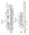
- Figure 1 is an enlarged view of a code carrying medium showing coded patterns in accordance with one embodiment of the present invention;
- Figure 2 is a diagrammatical illustration of an optical system which can be adopted in the encoded embodying the present invention;
- Figure 3 is a view showing the relationship between the code pattern and a linear array of photoelectrical elements constituting the photoelectrical sensor;
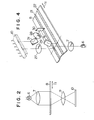
- Figure 4 is a perspective view showing another example of the optical system which can be used in the present invention;
- Figure 5 is a block diagram showing the overall arrangement of the encoder embodying the features of the present invention;
- Figure 6 (a) and (b) are diagrams showing the operations of the processing circuit in the encoder shown in Figure 5;
- Figure 7 is a perspective view of an optical system showing another embodiment of the present invention; and,
- Figure 8 is a viewsimilarto Figure 1 but showing a further embodiment of the present invention.
- Referring now to the drawings, particularly to Figure 1, there is shown a
code carrying medium 8 in accordance with one embodiment of the present invention. The medium includes afine reading track 21 and arough reading track 22 which are parallel with each other and extending in the lengthwise direction of themedium 8. Themedium 8 is moved in the direction shown by an arrow 11 in Figure 1. Thefine reading track 21 is divided into a plurality ofblocks 21a which are arranged in series along the length of thetrack 21. In each of theblocks 21a, there are formed amark pattern 12 and acode bar pattern 16. Themark pattern 12 includestransparent portion 12a and anopaque portion 12b whereas thecode bar pattern 16 includes a series of alternately arranged transparent andopaque bars - The
rough reading track 22 is divided into a plurality ofblocks 23 which are arranged in series along the length of thetrack 22. In each of theblocks 23, there is formed anaddress pattern 23a which contains an information of the address of theparticular block 23. In eachblock 23, theaddress pattern 23a is recorded in the direction perpendicular to the direction 11 of movement of themedium 8 as will be described in more detail later. Beneath thecode carrying medium 8,there is aphotoelectrical sensing device 10 comprising line sensors 10A and 10B. Each of the line sensors 10A and 10B includes a linear array of photoelectrical elements as well known in the art. - Figure 2 shows an optical system for reading the patterns on the
medium 8 by means of thesensing device 10. The optical system includes alight source 6 and acondenser lens 7 for directing the beam of light from thelight source 6 to themedium 8. The light beam which has passed through themedium 8 is focused by animaging lens 9 on thesensing device 10 to produce an image of the patterns on themedium 8. - Referring to Figure 3, there is shown the relationship between the
code bar pattern 16 and the linear sensor 10B. As described, the linear sensor 10B includes a linear array ofphotoelectrical sensing elements 15 which are arranged with a regular pitch P. Each of thebars code bar pattern 16 has a width W. The pitch P of theelements 15 in the line sensor 10B and the width W of eachbar code bar pattern 16 are slightly different from each other so as to produce a vernier relationship therebetween. In the specific example shown in Figure 3, the length containing tencode bars photoelectric elements 15 so that one-tenth of the pitch P of the photoelectric element can be detected by the principle of the vernier scale. Themark pattern 12 is provided for detecting the particular element orelements 15 on which thepattern 12 is projected and calculating the distance between such element or elements and a predetermined one of the elements which is usually referred to as an "index bit IB" to thereby make it possible to read the relative position of thespecific block 21 a with respect to the line sensor 10B by the order of the pitch P of theelements 15. - Referring back to Figure 1, the
rough reading track 22 is divided into a plurality of sub-tracks 22a through 22e which are arranged in a direction perpendicular to the direction of movement of themedium 8. In each of theblocks 23, the sub-tracks 22a through 22e are coded in a binary method so as to form theaforementioned address pattern 23a. The line sensor 10A is constructed in the same way as the line sensor 10B and arranged with its lengthwise direction coincided with the direction of arrangement of the sub-tracks 22a through 22e. Thus, it is possible to .detect the address of aparticular block 23 by the linear sensor 10A. It is therefore possible to carry out the reading based on the pitch P of thephotoelectric element 15 and the fine reading based on the principle of vernier scale to thereby determine the relative position of the code carrying medium 8 with respect to thesensing device 10. - Figure 4 shows a modified form of the optical system which may be used with the code carrying medium 8 shown in Figure 1. The optical system shown in Figure 4 is intended to make it possible to read the informations by a single
linear sensor 10. The beam of light from thelight source 6 is passed through thecondenser lens 7 and then through thecode carrying medium 8. The portion of the light beam which has passed through thefine reading track 21 is projected through the focusinglens 27 to thesensor 10. The portion of the light beam which has passed through therough reading track 22 is reflected bymirrors track 22 are rotated by 90°. The light beam from themirror 30 is then passed through a focusinglens 28 and reflected by amirror 31 to be projected on thesensor 10. Thus, the pattern recorded transversely on thetrack 22 is projected on thesensor 10 longitudinally along the array of the photoelectric elements in thesensor 10. - It will be understood from the foregoing descriptions that the patterns for fine reading are provided on a track separated from the track where the rough reading patterns are provided. Further, the binary bits constituting the rough reading patterns are arranged in a direction crossing the direction of the relative movement of the
code carrying medium 8. It is therefore possible to obtain an increased density of the fine reading patterns and to decrease the length of each recording block. The arrangements are thus convenient in reading more than one blocks for the purpose of ensuring accuracy of measurement, because the area of illumination may not necessarily be broadened. Even when the patterns are recorded on arcuate tracks, the reading can be carried out by a linear array of sensing elements without producing any significant error. Further, the reading can be made more rapidly than the previously discussed prior art. - In the embodiment shown in Figure 1, it will be noted that the
rough reading track 22 has twoblocks 23 in a length corresponding to one block length in thefine reading track 21. This arrangement is advantageous in preventing possible reading errors when the sensor 10A is on the border between two adjacent blocks on therough reading track 22. Assuming in Figure 1 that the sensor 10A is on the border between the block for the address "0" and the block for the address "1", the address reading will take the value "0" or "1" so that there will be a possibility of producing a large error if the value is simply added to the value of the fine reading. In the arrangement shown in Figure 1, the possibility of such an error can be avoided by the following procedure. For the purpose of explanation, it is assumed that the sensor 10B includes one hundred elements in the length corresponding to one block length on thefine reading track 8. When the address value as read by the sensor 10A is an odd number and the value of fine reading is greater than "twenty-five", the value "one" is subtracted from the address value, but the value "one" is added when the fine reading is smaller than "twenty-five". When the address value is an even number, the value "two" is subtracted from the address value where the fine reading value is greater than "seventy-five" whereas the address value is adopted as it is where the fine reading value is smaller than "seventy-five". It is preferred to adopt gray codes for the address codes in order to avoid reading errors at the border of the address code blocks. - Referring now to Figure 5, the code carrying medium 8 in accordance with one embodiment of the present invention is placed on a
movable member 45 such as a movable table of a machine tool. The informations on themedium 8 are read by an optical system including alight source 6, acondenser lens 7 and animaging lens 9, and aphotoelectric sensing device 10. The medium 8 carries coded patterns as shown in Figure 1 and the optical system as shown in Figure 2 may be used together with the linear sensors 10A and 10B as shown in Figure 1. Alternatively, the optical system as shown in Figure 4 may be used together with a singlelinear sensor 10. - A
pulse generator 32 is associated with thesensor 10 to apply thereto a start pulse 33 and a clock pulse 34. Thesensor 10 start to operate as soon as the start pulse 33 is received from thepulse generator 32 and produces anoutput 35 in synchronism with the clock pulse 34 from thepulse generator 32. Theoutput 35 from thesensor 10 is applied to anamplifier 36 which has an output connected with asample hold 37. The sample hold 37 functions to store as an analogue voltage the peak value of the output of each sensing element of thesensor 10. The output of the sample hold 37 is connected with an analogue-digital transducer 38 which converts the analogue voltage signal from the sample hold 37 to a digital value. The output of thetransducer 38 is connected with adigital memory 39 where the output signals from thesensor 10 are sequentially memorized. Thedigital memory 39 may be of a random access type and acounter 40 may be provided for receiving the clock pulse from thepulse generator 32. The output of thecounter 40 is applied to thememory 39 to sequentially store the output signals from the sequential elements in thesensor 10 whereby the addresses of the respective ones of the memorized signals can have direct correspondence with the bit numbers of thesensor 10. It should of course be noted that thecounter 40 must be reset either by the start pulse 33 or anend pulse 41 which may be applied thereto from thesensor 10. Asignal processing circuit 43 is provided for receiving thescan end pulse 41 from thesensor 10 and functions to transfer the data in thememory 39 to adata memory 42 when thescan end pulse 41 is received to perform data processing. - Referring now to Figures 1 and 6, it should be noted that the
transparent portion 12a in themark pattern 12 has a length corresponding to six sensing elements in thesensor 10 whereas theopaque portion 12b has a length corresponding to three elements in thesensor 10. Further, eachblock 21 a in thefine reading track 21 has ablock stop mark 12c at the end thereof, which comprises an opaque portion having a length corresponding to three elements in thesensor 10. Thecode bar pattern 16 includes thirty transparent andopaque bars rough reading track 22 has a width corresponding to four elements in thesensor 10. When the patterns on themedium 8 are projected on asensor 10 as shown in Figure 6(b), the elements in thesensor 10 produce output pulses as shown in Figure 6(a) where they receive images of the transparent portions. Then, the data processing is carried out by the following procedures. - (1) The beginning of the
transparent portion 12a of themark pattern 12 is detected by the decrease of the output pulse level in the output pulse of thesensor 10. In the example shown in Figure 6, this is detected by the No. 4 element in thesensor 10. - (2) The distance between the element referred to in the paragraph (1) and the index bit element 1B is detected. In the example shown in Figure 6, No. 27 element is selected as the index bit so that the distance corresponds to twenty-three elements. Where the sensing elements are arranged with a pitch of 10 um, the distance is 230 pm.
- (3)
Cyclic patterns code bar pattern 16 and the elements in thesensor 10. Thepoints patterns points point 46 is obtained as 18.98. It is thus possible to obtain a more accurate result by providing an increased number of code bars for performing averaging operations. This can be done by separating the address pattern blocks from the fine reading pattern blocks to thereby increase the area available for the code bars. It will be understood that due to the vernier relationship described previously, the positions of theintersections code carrying medium 8 and thesensor 10 as fully discussed in the aforementioned patent applications. - Where it is preliminary determined that the zero position for the
intersection 46 is apart toward right by a distance corresponding to ten elements in thesensor 10, the fine reading can be obtained from the value as obtained in the paragraph (1) and the value as obtained in this paragraph by carrying out the following calculation.
- This means that the
intersection 46 is shifted by a distance equal to 4.98 times the pitch between the elements in the sensor. Since there is a vernier relationship of 10:11 and the pitch between the elements is 10 pm, the fine reading is 4.98 pm. - (4) Then, the address of the particular block in question is read from the patterns in the
rough reading track 22. - (5) From the values obtained in the paragraphs (2) and (3), the lower digits of measurement can be obtained as follows.

- The value is then added to the value as obtained by the address code in the paragraph (4) to determine the relative displacement between the
code carrying medium 8 and thesensor 10. - Referring now to Figure 7, there is shown a further embodiment of the present invention in which the concept of the present invention is applied to a rotating apparatus. In this embodiment, the
code carrying medium 8 is in the form of a rotatable disc which is adapted to rotate about anaxis 0. Thedisc 8 has a peripheral portion formed with a circularfine reading track 21 and a circularrough reading track 22 both of which have patterns as thetracks disc 8 can be eliminated. Thus, the encoder shown in Figure 7 has a pair of optical systems for reading the patterns in thefine reading track 21 at diametrically opposite positions. Since the eccentricity of thedisc 8 is not large, it is unnecessary to read the rough reading track at two positions. - The optical system for reading the
fine reading track 21 at one position 58a includes alight source 50a and a condenser lens 51 a for directing a beam of light to thefine reading track 21 of thedisc 8. The light beam which has passed through thefine reading track 21 is reflected by amirror 52a and passed through a relay lens 53a to a mirror 54a to be reflected thereby. The light beam as reflected by the mirror 54a is directed to afurther mirror 55a to be reflected toward animaging lens 56a. The light beam which has passed through thelens 56a is again reflected by amirror 57a toward aphotoelectric sensor 10 to produceimages 59a of the patterns on thefine reading track 21. For carrying out a similar reading at the diametricallyopposite position 58b, there is provided another optical system which is essentially the same as that described above. Therefore, corresponding parts are shown by the same reference numerals with suffix b but detailed descriptions will not be made. - There is further provided an optical system including a light source 63 and a condenser lens 64 for directing a beam of light from the light source 63 to the
rough reading track 22. The light beam which has passed through therough reading track 22 at aposition 60 is passed through an imaging lens 61 to thesensor 10 to form thereon images 62 of the patterns on therough reading track 22. - Figure 8 shows a further embodiment of the present invention in which the
code carrying medium 8 has four separated tracks. More particularly, themedium 8 has afine reading track 21a havingcode bars track 23 having slanted oroblique patterns rough reading track 22 having address patterns, and areference track 25 for determining the position in the direction perpendicular to the direction 11 of movement of themedium 8. Themedium 8 is divided into a plurality of blocks which are arranged in series in the direction 11 of movement of themedium 8. Theaddress track 22 has address patterns for determining the addresses of the respective blocks. Fine readings can be made by the sensor 10B which detects the code bar patterns on thetrack 21 a in the same manner as in the previous embodiment. - The
oblique patterns - (1) Where the sensor 10A detects that a
thinner pattern 24b is above athicker pattern 24a and the address reading is of an odd number, the address reading itself is added with a value as obtained by reading thethinner pattern 24b. Where the address reading is of an even number, the address reading is subtracted by one and added with the reading of thethinner pattern 24b. - (2) Where a
thicker pattern 24a is above athinner pattern 24b and the address reading is of an even number, the address reading itself is added with the value as obtained by reading thethicker pattern 24a. Where the address reading is of an odd number, the address reading is subtracted with one and added with the reading of the thicker pattern. - The
reference track 25 on themedium 8 determines the reference position of the medium 8 with respect to the sensor 10A. The positions of theoblique patterns code carrying medium 8 and the sensor 10A in the direction perpendicular to the direction 11, thereference track 25 is provided and the reference position on the sensor 10A is determined as the position where the image of thetrack 25 is projected. It should further be noted that by detecting the position of thetrack 25 on the sensor 10A, it becomes possible to detect the positions of the sub-tracks 22a through 22e of therough reading track 22 more accurately. Thus, it becomes unnecessary to make adjustments so that the sub-tracks 22a through 22e be projected on predetermined positions on the sensor 10A. It should further be noted that, by providing a pair of reference tracks at the opposite sides of therough reading track 22 to thereby make it possible to detect the width of thetrack 22 on the sensor 10A, it becomes unnecessary to make detailed adjustments of the power of the imaging lens and the alignment of the mirrors in the optical system.
Claims (3)
characterized in that
Applications Claiming Priority (2)
| Application Number | Priority Date | Filing Date | Title |
|---|---|---|---|
| JP126013/81 | 1981-08-13 | ||
| JP56126013A JPS5829093A (en) | 1981-08-13 | 1981-08-13 | Absolute encoder |
Publications (3)
| Publication Number | Publication Date |
|---|---|
| EP0072549A2 EP0072549A2 (en) | 1983-02-23 |
| EP0072549A3 EP0072549A3 (en) | 1985-05-15 |
| EP0072549B1 true EP0072549B1 (en) | 1989-04-26 |
Family
ID=14924560
Family Applications (1)
| Application Number | Title | Priority Date | Filing Date |
|---|---|---|---|
| EP82107383A Expired EP0072549B1 (en) | 1981-08-13 | 1982-08-13 | Absolute encoder |
Country Status (4)
| Country | Link |
|---|---|
| US (1) | US4602242A (en) |
| EP (1) | EP0072549B1 (en) |
| JP (1) | JPS5829093A (en) |
| DE (2) | DE3279655D1 (en) |
Families Citing this family (28)
| Publication number | Priority date | Publication date | Assignee | Title |
|---|---|---|---|---|
| DE3427411A1 (en) * | 1984-07-25 | 1986-02-06 | Dr. Johannes Heidenhain Gmbh, 8225 Traunreut | MEASURING DEVICE |
| DE3526206A1 (en) * | 1985-07-23 | 1987-02-05 | Heidenhain Gmbh Dr Johannes | MEASURING DEVICE |
| JPH07111358B2 (en) * | 1986-01-23 | 1995-11-29 | 石川島播磨重工業株式会社 | Absolute terrain position detection device |
| US4733069A (en) * | 1986-02-14 | 1988-03-22 | Optec Co., Ltd. | Position encoder using a laser scan beam |
| US4967075A (en) * | 1986-09-16 | 1990-10-30 | High Yield Technology | Velocity monitoring method and apparatus |
| SE460928B (en) * | 1986-10-13 | 1989-12-04 | Johansson Ab C E | ABSOLUTELY MEASURING SCALE SYSTEM |
| JP2645350B2 (en) * | 1987-01-28 | 1997-08-25 | チノン株式会社 | Serial dot matrix printer |
| DE3809569A1 (en) * | 1988-03-22 | 1989-10-05 | Frankl & Kirchner | POSITION SENSOR |
| JP2567036B2 (en) * | 1988-05-10 | 1996-12-25 | キヤノン株式会社 | Optical encoder |
| IT1217650B (en) * | 1988-05-19 | 1990-03-30 | Microptronics Srl | DEVICE FOR OPTICAL READING OF PLANAR SUPPORTS |
| KR900702328A (en) * | 1988-07-12 | 1990-12-06 | 후루노 기요까따 | Rotary encoder |
| JP2715655B2 (en) * | 1990-11-21 | 1998-02-18 | 株式会社デンソー | Non-contact type moving amount measuring method and device |
| US5254919A (en) * | 1991-03-22 | 1993-10-19 | Eastman Kodak Company | Encoder system using linear array sensor for high resolution |
| US5336884A (en) * | 1992-07-01 | 1994-08-09 | Rockwell International Corporation | High resolution optical hybrid absolute incremental position encoder |
| EP0660085B1 (en) * | 1993-12-22 | 1997-07-09 | Troll, Christian, Dr.-Ing. habil. | Absolute position measuring device |
| US7387253B1 (en) | 1996-09-03 | 2008-06-17 | Hand Held Products, Inc. | Optical reader system comprising local host processor and optical reader |
| KR100264312B1 (en) * | 1995-10-13 | 2000-08-16 | 디지래드 | Semiconductor radiation detector with enhanced charge collection |
| US5774074A (en) * | 1997-01-21 | 1998-06-30 | Hewlett-Packard Company | Multi-track position encoder system |
| GB9807020D0 (en) * | 1998-04-02 | 1998-06-03 | Bamford Excavators Ltd | A method of marking a mechanical element, an encoding scheme, a reading means for said marking and an apparatus for determining the position of said element |
| US6017114A (en) * | 1998-09-30 | 2000-01-25 | Hewlett-Packard Company | Shifted element scanning/printing routine coordinated with media advance |
| DE10244234A1 (en) * | 2002-09-23 | 2004-03-25 | Dr. Johannes Heidenhain Gmbh | Position measuring device |
| US20070114370A1 (en) * | 2003-10-10 | 2007-05-24 | Smith Ronald H | Fiber optic remote reading encoder |
| US7166833B2 (en) * | 2003-10-10 | 2007-01-23 | Optelecom-Nkf | Fiber optic remote reading encoder |
| US7191943B2 (en) * | 2004-07-28 | 2007-03-20 | Caterpillar Inc | Robust barcode and reader for rod position determination |
| WO2009103342A1 (en) | 2008-02-22 | 2009-08-27 | Trimble Jena Gmbh | Angle measurement device and method |
| JP5159663B2 (en) | 2009-02-13 | 2013-03-06 | キヤノン株式会社 | Origin detecting device, displacement measuring device and electronic device |
| KR101456882B1 (en) | 2012-05-18 | 2014-11-03 | 서울대학교산학협력단 | Digital opto-electrical pulse application method for correcting bit error of vernier-type optical encoder |
| WO2013172564A1 (en) * | 2012-05-18 | 2013-11-21 | Snu R&Db Foundation | Digital opto-electric pulse application method for correcting bit error of vernier-type optical encoder |
Family Cites Families (11)
| Publication number | Priority date | Publication date | Assignee | Title |
|---|---|---|---|---|
| US2928953A (en) * | 1956-10-25 | 1960-03-15 | Bassler Fritz | Method and apparatus for aligning record carriers relative to a record scanner |
| US3458709A (en) * | 1964-06-24 | 1969-07-29 | North American Rockwell | Time reference angle encoder using radiation sensitive means |
| US3509562A (en) * | 1966-07-25 | 1970-04-28 | Baldwin Co D H | Analog to digital encoder |
| CH502580A (en) * | 1969-01-24 | 1971-01-31 | Oerlikon Buehrle Ag | Device with a photocell arrangement for determining the position of an equidistantly divided scale |
| FR2310549A1 (en) * | 1975-05-07 | 1976-12-03 | Sagem | IMPROVEMENTS TO OPTICAL DEVICES FOR DETERMINING THE POSITION OF A MOBILE ORGAN |
| GB1574439A (en) * | 1976-02-03 | 1980-09-10 | Solartron Electronic Group | Displacement transducers |
| DE2811807A1 (en) * | 1978-03-16 | 1979-09-20 | Joachim Dr Ing Wernicke | Digital coder for angular position of shaft - employs vernier principle and has photoelectric devices to provide accurate measurement |
| EP0010930B1 (en) * | 1978-10-30 | 1983-09-21 | Sanden Corporation | Scroll-type fluid compressor units |
| EP0013799B1 (en) * | 1978-12-19 | 1985-10-02 | Kabushiki Kaisha Toshiba | Encoder for length or angle measuring devices with high accuracy |
| JPS576994A (en) * | 1980-06-17 | 1982-01-13 | Tokyo Optical | Coding board for encoder |
| JPS57104815A (en) * | 1980-12-20 | 1982-06-30 | Asahi Optical Co Ltd | Angle measuring apparatus employing line sensor |
-
1981
- 1981-08-13 JP JP56126013A patent/JPS5829093A/en active Granted
-
1982
- 1982-08-13 EP EP82107383A patent/EP0072549B1/en not_active Expired
- 1982-08-13 DE DE8282107383T patent/DE3279655D1/en not_active Expired
- 1982-08-13 DE DE198282107383T patent/DE72549T1/en active Pending
-
1985
- 1985-09-11 US US06/774,859 patent/US4602242A/en not_active Expired - Lifetime
Also Published As
| Publication number | Publication date |
|---|---|
| DE72549T1 (en) | 1985-08-14 |
| EP0072549A2 (en) | 1983-02-23 |
| JPS5829093A (en) | 1983-02-21 |
| JPH0157292B2 (en) | 1989-12-05 |
| US4602242A (en) | 1986-07-22 |
| DE3279655D1 (en) | 1989-06-01 |
| EP0072549A3 (en) | 1985-05-15 |
Similar Documents
| Publication | Publication Date | Title |
|---|---|---|
| EP0072549B1 (en) | Absolute encoder | |
| EP0042179B1 (en) | Encoder | |
| EP0100243B1 (en) | Position sensor | |
| US4631519A (en) | Position measuring apparatus | |
| US5235181A (en) | Absolute position detector for an apparatus for measuring linear angular values | |
| US4421980A (en) | Position encoder with closed-ring diode array | |
| EP0577104B1 (en) | High resolution optical hybrid digital-analog position encoder | |
| EP0361457B1 (en) | Method and apparatus for detecting a reference position of a rotating scale | |
| US4794251A (en) | Apparatus for measuring lengths or angles | |
| US4933673A (en) | Encoder | |
| JP2004529344A (en) | Absolute position measurement method | |
| JPH0658779A (en) | Measuring device | |
| GB2126444A (en) | Position measuring apparatus | |
| JPS61111417A (en) | Position detector | |
| EP0039921B1 (en) | Encoder device and method of use of it | |
| JP3442869B2 (en) | Optical absolute encoder | |
| JP4580060B2 (en) | Scanning unit of optical position measuring device | |
| JPS63117214A (en) | Displacement measuring device | |
| JP2697159B2 (en) | Absolute position detector | |
| JPH0141925B2 (en) | ||
| JPH0157291B2 (en) | ||
| JPH05196451A (en) | Length measuring or angle measuring device | |
| JPH02168115A (en) | Absolute encoder | |
| JPS6343683B2 (en) | ||
| KR100678619B1 (en) | Digital optical angle sensor |
Legal Events
| Date | Code | Title | Description |
|---|---|---|---|
| PUAI | Public reference made under article 153(3) epc to a published international application that has entered the european phase |
Free format text: ORIGINAL CODE: 0009012 |
|
| AK | Designated contracting states |
Designated state(s): CH DE FR GB LI SE |
|
| PUAL | Search report despatched |
Free format text: ORIGINAL CODE: 0009013 |
|
| EL | Fr: translation of claims filed | ||
| AK | Designated contracting states |
Designated state(s): CH DE FR GB LI SE |
|
| DET | De: translation of patent claims | ||
| 17P | Request for examination filed |
Effective date: 19850717 |
|
| 17Q | First examination report despatched |
Effective date: 19860908 |
|
| D17Q | First examination report despatched (deleted) | ||
| GRAA | (expected) grant |
Free format text: ORIGINAL CODE: 0009210 |
|
| AK | Designated contracting states |
Kind code of ref document: B1 Designated state(s): CH DE FR GB LI SE |
|
| REF | Corresponds to: |
Ref document number: 3279655 Country of ref document: DE Date of ref document: 19890601 |
|
| ET | Fr: translation filed | ||
| REG | Reference to a national code |
Ref country code: CH Ref legal event code: PFA Free format text: KABUSHIKI KAISHA TOPCON |
|
| REG | Reference to a national code |
Ref country code: FR Ref legal event code: CD |
|
| PLBE | No opposition filed within time limit |
Free format text: ORIGINAL CODE: 0009261 |
|
| STAA | Information on the status of an ep patent application or granted ep patent |
Free format text: STATUS: NO OPPOSITION FILED WITHIN TIME LIMIT |
|
| 26N | No opposition filed | ||
| PGFP | Annual fee paid to national office [announced via postgrant information from national office to epo] |
Ref country code: GB Payment date: 19920731 Year of fee payment: 11 Ref country code: FR Payment date: 19920731 Year of fee payment: 11 |
|
| PG25 | Lapsed in a contracting state [announced via postgrant information from national office to epo] |
Ref country code: GB Effective date: 19930813 |
|
| GBPC | Gb: european patent ceased through non-payment of renewal fee |
Effective date: 19930813 |
|
| PG25 | Lapsed in a contracting state [announced via postgrant information from national office to epo] |
Ref country code: FR Effective date: 19940429 |
|
| REG | Reference to a national code |
Ref country code: FR Ref legal event code: ST |
|
| EAL | Se: european patent in force in sweden |
Ref document number: 82107383.0 |
|
| PGFP | Annual fee paid to national office [announced via postgrant information from national office to epo] |
Ref country code: SE Payment date: 20000719 Year of fee payment: 19 |
|
| PGFP | Annual fee paid to national office [announced via postgrant information from national office to epo] |
Ref country code: DE Payment date: 20000831 Year of fee payment: 19 |
|
| PGFP | Annual fee paid to national office [announced via postgrant information from national office to epo] |
Ref country code: CH Payment date: 20001106 Year of fee payment: 19 |
|
| PG25 | Lapsed in a contracting state [announced via postgrant information from national office to epo] |
Ref country code: SE Free format text: LAPSE BECAUSE OF NON-PAYMENT OF DUE FEES Effective date: 20010814 |
|
| PG25 | Lapsed in a contracting state [announced via postgrant information from national office to epo] |
Ref country code: LI Free format text: LAPSE BECAUSE OF NON-PAYMENT OF DUE FEES Effective date: 20010831 Ref country code: CH Free format text: LAPSE BECAUSE OF NON-PAYMENT OF DUE FEES Effective date: 20010831 |
|
| EUG | Se: european patent has lapsed |
Ref document number: 82107383.0 |
|
| REG | Reference to a national code |
Ref country code: CH Ref legal event code: PL |
|
| PG25 | Lapsed in a contracting state [announced via postgrant information from national office to epo] |
Ref country code: DE Free format text: LAPSE BECAUSE OF NON-PAYMENT OF DUE FEES Effective date: 20020501 |