EP0040571B1 - Vorrichtung zum Stapeln einander entlang einen Förderer nachfolgender Gegenstände - Google Patents
Vorrichtung zum Stapeln einander entlang einen Förderer nachfolgender Gegenstände Download PDFInfo
- Publication number
- EP0040571B1 EP0040571B1 EP81400779A EP81400779A EP0040571B1 EP 0040571 B1 EP0040571 B1 EP 0040571B1 EP 81400779 A EP81400779 A EP 81400779A EP 81400779 A EP81400779 A EP 81400779A EP 0040571 B1 EP0040571 B1 EP 0040571B1
- Authority
- EP
- European Patent Office
- Prior art keywords
- frames
- carriages
- stop
- transport path
- lifting
- Prior art date
- Legal status (The legal status is an assumption and is not a legal conclusion. Google has not performed a legal analysis and makes no representation as to the accuracy of the status listed.)
- Expired
Links
Images


Classifications
-
- B—PERFORMING OPERATIONS; TRANSPORTING
- B65—CONVEYING; PACKING; STORING; HANDLING THIN OR FILAMENTARY MATERIAL
- B65G—TRANSPORT OR STORAGE DEVICES, e.g. CONVEYORS FOR LOADING OR TIPPING, SHOP CONVEYOR SYSTEMS OR PNEUMATIC TUBE CONVEYORS
- B65G57/00—Stacking of articles
- B65G57/30—Stacking of articles by adding to the bottom of the stack
- B65G57/301—Stacking of articles by adding to the bottom of the stack by means of reciprocatory or oscillatory lifting and holding or gripping devices
- B65G57/303—Stacking of articles by adding to the bottom of the stack by means of reciprocatory or oscillatory lifting and holding or gripping devices the stack being lowered by mobile grippers or holders onto added articles
Definitions
- the present invention relates to a stacker for stacking products, each consisting of a plate supporting an object, of the type comprising two frames arranged on either side of a transport path along which the products circulate one after the other. others ; means for immobilizing the products when they are between the frames; two lift trucks vertically movable along the frames, these trucks facing each other and each comprising lifting members comprising a lifting wing capable of advancing under the product immobilized between the frames, the lifting members being articulated around a horizontal axis extending parallel to the transport track and being able to pivot between an active position in which they are in abutment against a retainer fixed on the corresponding carriage while their lifting wing advances horizontally above the track transport, and an inactive position in which they are distant from the retainer while their lifting wing extends outside the transport path; and drive means for cyclically communicating to the carriages an upward movement during which their lifting members raise the immobilized product to a height sufficient to allow the arrival and stopping of a new product between the frames, then a movement
- the document FR-A-1 494 910 describes a stacker of this type whose lifting members pivot between their active position and their inactive position under the control of rollers moving along tortuous paths defined by straight ramps, cams and retractable shutters.
- the present invention proposes to overcome these drawbacks and, to do this, it relates to a stacker of the aforementioned type which is characterized in that the pivot axis of the lifting members of the same carriage is provided with a radial lug capable of cooperating with a bypass cam pivotally mounted on the corresponding frame, around an axis perpendicular to the pivot axis of the lifting members; and in that the bypass cam is elastically biased against a stop provided on said corresponding frame, the stop being arranged so that, during the downward movement of the corresponding carriage, the corresponding lug causes the lifting members to move in their inactive position when it meets the bypass cam which is immobilized against the stop, and that during the upward movement of the corresponding carriage, the associated lug causes the bypass cam to pivot around the axis so as to move it away from the stopper and retract it.
- the lifting members can therefore, thanks to the bypass cams, pivot to their inactive position before they meet the plate of the new product.
- the latter is therefore protected against damage which the bearing wing of the lifting members could cause it by sliding against it.
- the lugs are not liable to be damaged by the bypass cams since these are retractable.
- the drive means consist of two sets of identical cams and on which the carriages rest, each assembly bearing on a horizontal spacer provided on the corresponding frame and comprising two wedged cams each on a lever forming one of the transverse sides of a deformable parallelogram, and by a jack extending parallel to the transport track, this jack being interposed between a fixed base and a connecting arm connecting the two deformable parallelograms.
- the drive means raise the carriages against the action exerted by tension springs, interposed between them and the lower part of the frames.
- tension springs interposed between them and the lower part of the frames.
- the stacker according to the present invention is further characterized in that it comprises means for pushing the stack of products when it reaches a predetermined height, these means bringing the stack downstream of the frames by moving it along the track. transport.
- the means for pushing the stack comprise at least one cleat which can be moved alternately along the part of the transport path located between the frames, this cleat rising above the plate of the product resting on the transport path. and being capable of being retracted when it moves in the direction in which it does not exert its pushing action.
- the cleat is articulated at one of the ends of a rack running along the transport track and movable parallel to the latter under the action of a motor member engaged with it.
- the stacker according to the present invention is further characterized in that the means provided for immobilizing the products between the frames are constituted by stops fixed to the front end of each carriage, these stops being in front of the plate of the product to be immobilized when the carriages are in their high position, and under the transport track when these are in their low position.
- the two frames each comprise two vertical uprights constituted by U-shaped profiles whose wings are parallel to each other and face each other, while the carriages are each constituted by a horizontal beam whose ends carry rollers cooperating with the wings of the vertical uprights of the corresponding frame.
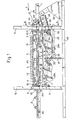
- the stacker according to the invention is more particularly intended for stacking molded concrete objects resting on a demoulding plate, these objects being able for example to consist of slabs, fence posts, etc. It is used in conjunction with a transport track essentially comprising two parallel beams 1 extending horizontally and carrying rollers 2 on which the products to be stacked circulate one after the other in the direction of the arrow F.
- the products are made up by a release board 3 provided with feet 4 and by a slab 5 resting on the board.
- the spacing of the feet 4 is greater than that of the side members 1 and that thus the boards 3 can rest on the rollers by means of their lower face.
- the stacker comprises first of all two identical frames arranged on either side of the transport track, each frame comprising two vertical uprights 6 connected below their central part by a horizontal spacer 7 and constituted by U-shaped profiles implanted on the ground in such a way that their wings are parallel to each other and turned towards each other.
- the stacker also includes two forklifts 8 movable along the frames between a low position visible in Figures 1 and 3 and a high position visible in Figure 2.
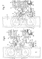
- Each of these trucks is formed by a horizontal beam 9 at the ends of which are fixed two plates 10 each carrying two rollers 11 cooperating with the wings of the corresponding amount 6.
- the longitudinal members 9 are U-shaped profiles, the branches of which face outwards relative to the transport track and that the plates 10 are in the form of trapezoids, the large base is in the plane containing the ends of the wings of the associated spar 9 and the small base of which extends into the space delimited between the two frames of the stacker.
- each carriage support, near their small base, a horizontal shaft 12 extending parallel to the transport path.
- This shaft which serves as a support for two angles 13 each comprising a lifting wing 14 and an immobilization cleat 15, can pivot in the plates 10 and allow the angles to pivot between an active position (visible for example in FIG. 4 ) in which their wing 14 projects horizontally above the transport track while their cleat 15 is in abutment against a retainer 16 fixed on the base of the spar 9, and an inactive position (visible in FIG. 8) in which their wing 14 is outside the transport track while their cleat 15 is below the retainer 16.
- Tension springs 17, the ends of which are respectively fixed on the base of the side member 9 and on the wing 14 of the angles are provided to return the latter to their active position.
- the shaft 12 extends beyond the end plates 10 and that it carries at each of its ends a radial lug 18 projecting in the direction of the track. transport so as to be able to cooperate with a bypass cam 19 pivotally mounted on the wing of the corresponding upright 6 which is turned towards the transport track.
- the bypass cams 19 are constituted by an L-shaped plate, extending parallel to the upright 6.
- this plate On its face facing the upright 6, this plate carries an axis 20 by through which it can be pivotally mounted on the upright 6 and a protrusion 21 provided with a bore 22 intended to receive one of the ends of a tension spring 23 the other end of which is hooked on a lug 24 fixed on the upright 6. Thanks to the spring 23, the small branch of the plate is biased against a stop 25 fixed on the external face of the base of the upright 6 and then extends horizontally.
- the axis 20 is fixed at the junction of the two arms of the plate and that a rounded 26 ensures the connection of the outer edges of these two branches.
- the bypass cams 19 are fixed on the uprights 6 at a height such that the pins 18 of the shafts 12 meet their large branches when the carriages are in a position close to their low position.
- the cooperation between the lugs 18 and the bypass cams 19 will however be explained in more detail below during the description of the operation of the stacker and it is therefore not necessary to describe it further here.
- each carriage carries on its front plate 10 (the one which is downstream) a stop 27 which is particularly clearly visible in FIGS. 6 to 9.
- This stop which is perpendicular to the transport track, advances in front of the plate 3 of the product located between the frames of the stacker when the carriages 8 are in their high position (FIG. 6) and descends under the transport track when these move away from their high position (FIGS. 7 to 9) .
- the stops 27 the product which arrives between the stacker frames, when the carriages are in the high position, can therefore be immobilized in a precise position.
- the spar 9 of each carriage rests on two identical cams 28a, 28b extending parallel to the transport track.
- the cams 28a are fixed to the ends of a transverse shaft 29 resting on bearings 30 mounted on the spacers 7 of the two frames of the stacker.
- the cams 28b are fixed to the ends of another transverse shaft 31 resting on bearings 32 mounted on the spacers 7.
- Two parallel levers 33 are articulated on a connecting arm 34 connecting their lower end. They are also articulated at one end of a connecting rod 35 extending parallel to the corresponding spacer 7, the other end of this connecting rod being articulated for its part at the lower end of a lever 36 whose the upper end is wedged on the shaft 31.
- the levers 33 and 36 are identical and form the transverse sides of two deformable parallelograms, the longitudinal sides of which are constituted by the connecting rods 35 and the centers of the shafts 29 and 31.
- the link arm 34 is coupled to the rod 37 of a jack 38 whose cylinder 39 is articulated on a base 40 fixed under the transport track.
- the cylinder 38 extends parallel thereto. When activated, it causes the deformation of the two parallelograms, which forces the cams 28a and 28b to pivot between their extreme positions visible respectively in FIGS. 1 and 3 and in FIG. 2.
- cams 28a and 28b have a sufficiently long cam surface so that in the high position of the carriages 8, a product can be advanced between the uprights 6 of the frames without risking being hampered by the product which is supported by the lifting wings 14 of the angles 13.
- the stacker according to the invention also comprises two pusher cleats 43 movable alternately along the side members 1 of the transport track, between a retracted position (visible in FIGS. 1 and 2) in which they are upstream of the two frames and a advanced position (not shown) in which they are downstream of said frames.
- pinions 46 which are identical, are wedged on a connecting shaft capable of rotating under the control of a conventional motor not shown.
- the tabs 43 rise above the plates of the various products on the transport path and are held in their projecting position by a return spring 47 connecting them to their respective slide.
- This arrangement has the advantage of allowing them to retract either when a plate 3, moving in the direction of the arrow F, passes over them, or when they return to their retracted position while 'a plate 3 is already between the uprights 6.
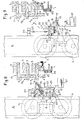
- angles 13 are in their active position.
- their immobilizing lugs 15 are in abutment against the retainers 16 while their lifting wings 14 extend horizontally and advance under the longitudinal sides of the plate 3 of the lower product P 2 .
- the stops 27 provided at the front end of the carriages 8 project in front of the plate 3 of the product P 3 which they immobilized between the uprights 6, the latter having been able to pass freely under the product P 2 whose height lifting capacity, determined by the length of the surfaces cam cam 28a and 28b is sufficient to allow this passage.
- the cylinder 38 is now actuated so that its rod retracts.
- the latter then pulls the link arm 34 in the direction of the base 40, which causes the deformation of the parallelograms and allows the cams 28a and 28b to pivot in the direction of the arrows G visible in FIG. 2.
- the carriages therefore initiate their descent with the assistance of the springs 41 which force them to remain in contact with the cam surfaces of the cams 28a and 28b.
- the cylinder 38 is now actuated in the opposite direction and thus allows the carriages 8 to begin their upward movement.
- the lugs 18 immediately meet the rounded 26 of the bypass cams 19 and force them to retract against the return force of the springs 23, by pivoting about their axis 20, in the direction of the arrow I (see Figure 10).
- the cams 19 thus prevent the lugs 18 and the angles 13 from being subjected to an abnormal resistive torque.
- a new product can now be advanced along the transport track and brought between the frames of the stacker where the stops 27 of the carriages will ensure its immobilization.
- the carriages are ready to come down so that their angles can support this new product which will then constitute the lower element of the stack being formed.
- the control of the jack 38 and the arrival of the products between the frames can of course be fully automated, which allows the carriages 8 to move continuously between their low and high positions and therefore the stack of products to form without any intervention. manual.
- the jack 38 ceases to be actuated as soon as the carriages 8 arrive in their low position while the pinion drive motor 46 starts to move in order to move the racks 45 in the direction of arrow F.
- the tabs 43 then push the stack of products until it is downstream of the stacker frames.
- the pinions 46 are driven in opposite directions in order to bring the cleats 43 back into their retracted position visible in FIGS. 1 and 2.
- the triggering of the motor controlling the rotation of the pinions 46 can of course be ensured automatically, for example as a function of signals supplied by limit switches or counting devices adjusted on the number of products which the batteries to be produced must contain.
- the plates 3 could have no feet. In this case, they would then rest directly on the upper face of the products in the stack which would be located under them.
Landscapes
- Engineering & Computer Science (AREA)
- Mechanical Engineering (AREA)
- Pile Receivers (AREA)
- Stacking Of Articles And Auxiliary Devices (AREA)
- Warehouses Or Storage Devices (AREA)
- Discharge By Other Means (AREA)
Claims (9)
Priority Applications (1)
| Application Number | Priority Date | Filing Date | Title |
|---|---|---|---|
| AT81400779T ATE10181T1 (de) | 1980-05-19 | 1981-05-18 | Vorrichtung zum stapeln einander entlang einen foerderer nachfolgender gegenstaende. |
Applications Claiming Priority (2)
| Application Number | Priority Date | Filing Date | Title |
|---|---|---|---|
| FR8011122 | 1980-05-19 | ||
| FR808011122A FR2482569B1 (fr) | 1980-05-19 | 1980-05-19 | Gerbeur pour empiler des produits circulant les uns a la suite des autres le long d'une voie de transport |
Publications (2)
| Publication Number | Publication Date |
|---|---|
| EP0040571A1 EP0040571A1 (de) | 1981-11-25 |
| EP0040571B1 true EP0040571B1 (de) | 1984-11-07 |
Family
ID=9242098
Family Applications (1)
| Application Number | Title | Priority Date | Filing Date |
|---|---|---|---|
| EP81400779A Expired EP0040571B1 (de) | 1980-05-19 | 1981-05-18 | Vorrichtung zum Stapeln einander entlang einen Förderer nachfolgender Gegenstände |
Country Status (4)
| Country | Link |
|---|---|
| EP (1) | EP0040571B1 (de) |
| AT (1) | ATE10181T1 (de) |
| DE (1) | DE3167043D1 (de) |
| FR (1) | FR2482569B1 (de) |
Families Citing this family (2)
| Publication number | Priority date | Publication date | Assignee | Title |
|---|---|---|---|---|
| FI84461C (fi) * | 1990-05-04 | 1991-12-10 | Partek Concrete Oy Ab | Foerfarande och anordning foer foerflyttning av betongplattor. |
| FI20135879L (fi) * | 2013-09-02 | 2015-03-03 | Elematic Oy Ab | Menetelmä, nosto ja pinoamislaitteisto sekä kiertomuottilinjavalulaitteisto betonituotteiden valamiseksi |
Family Cites Families (4)
| Publication number | Priority date | Publication date | Assignee | Title |
|---|---|---|---|---|
| US3190466A (en) * | 1963-09-18 | 1965-06-22 | Fruit Equipment Service | Bin stacker and de-stacker mechanism |
| US3343694A (en) * | 1963-10-15 | 1967-09-26 | Kaukas Ab Oy | Method for composing a timber packet |
| FR1494910A (fr) * | 1966-07-25 | 1967-09-15 | Appareil pour palettiser et dépalettiser | |
| FR2075832A7 (de) * | 1971-01-21 | 1971-10-08 | Martineau Claude |
-
1980
- 1980-05-19 FR FR808011122A patent/FR2482569B1/fr not_active Expired
-
1981
- 1981-05-18 EP EP81400779A patent/EP0040571B1/de not_active Expired
- 1981-05-18 DE DE8181400779T patent/DE3167043D1/de not_active Expired
- 1981-05-18 AT AT81400779T patent/ATE10181T1/de active
Also Published As
| Publication number | Publication date |
|---|---|
| DE3167043D1 (en) | 1984-12-13 |
| EP0040571A1 (de) | 1981-11-25 |
| FR2482569B1 (fr) | 1985-07-26 |
| ATE10181T1 (de) | 1984-11-15 |
| FR2482569A1 (fr) | 1981-11-20 |
Similar Documents
| Publication | Publication Date | Title |
|---|---|---|
| EP2625121B1 (de) | Lager für reifenkarkassen | |
| EP0537075B1 (de) | Anlage zum Immobilisieren eines Transportfahrzeuges in einer vorherbestimmten Überfahrlage | |
| CH639045A5 (fr) | Dispositif pour introduire des paquets de feuilles dans une machine les travaillant. | |
| EP3464075A1 (de) | Vibrierende vorrichtung zur neuanordnung in reihenfolge von faltschachteln in einem behälter, ausgabeförderer und verfahren zur ausgabe von behältern | |
| EP0374019A1 (de) | System zum Transportieren und Ablegen von mindestens einem Brückenteil von einem Fahrzeug, wie ein Pionierpanzer | |
| EP0040571B1 (de) | Vorrichtung zum Stapeln einander entlang einen Förderer nachfolgender Gegenstände | |
| EP0738675A2 (de) | Lagerung mittels mobiler Wagen mit geneigtem Chassis | |
| EP0131082B1 (de) | Vorrichtung zum Stellen von Paletten auf einen Ladeplatz | |
| FR2484380A1 (fr) | Procede pour le retournement et la manutention d'un objet substantiellement plat, tel qu'une meule de fromage et dispositif permettant la mise en oeuvre de ce procede | |
| CH663780A5 (fr) | Installation de stockage dynamique, notamment pour produits fragiles tels que fromages. | |
| EP0243268A1 (de) | Vorrichtung zum Fördern mit Laden und Entladen von weichen Teigprodukten | |
| BE1003872A5 (fr) | Systeme de support sur voie. | |
| EP0040570B1 (de) | Maschine zur Herstellung von Formlingen, insbesondere aus Beton | |
| FR2634471A1 (fr) | Dispositif pour le positionnement et l'arret d'objets deplaces sur un transporteur | |
| EP0330556B1 (de) | Drehscheibe zum Ausstellen eines Kraftfahrzeuges | |
| FR2728147A1 (fr) | Table telescopique a rouleaux, a deploiement assiste | |
| EP0374194B1 (de) | Antriebssystem und anwendungsverfahren für auf einer schiene bewegbare wagen | |
| EP0255448B1 (de) | Vorrichtung zum Fördern von Kästen, insbesondere Kästen mit beweglichem Boden zum Umladen von Gegenständen auf gleichbleibendem Niveau | |
| EP0609164B1 (de) | Automatische Verschiebevorrichtung für Filterpresse | |
| FR2525571A1 (fr) | Balancelle polyvalente a prehension et liberation automatiques de la charge transportee | |
| BE564933A (de) | ||
| CH343290A (fr) | Procédé de chargement et de déchargement de palettes de manutention et appareil pour la mise en oeuvre de ce procédé | |
| FR2639331A1 (fr) | Dispositif de separation de palettes pour couloir de stockage dynamique | |
| FR2716875A1 (fr) | Dispositif de manutention pour palettes. | |
| CH288043A (fr) | Convoyeur. |
Legal Events
| Date | Code | Title | Description |
|---|---|---|---|
| PUAI | Public reference made under article 153(3) epc to a published international application that has entered the european phase |
Free format text: ORIGINAL CODE: 0009012 |
|
| AK | Designated contracting states |
Designated state(s): AT BE CH DE GB IT LU NL SE |
|
| 17P | Request for examination filed |
Effective date: 19820419 |
|
| GRAA | (expected) grant |
Free format text: ORIGINAL CODE: 0009210 |
|
| AK | Designated contracting states |
Designated state(s): AT BE CH DE GB IT LI LU NL SE |
|
| PG25 | Lapsed in a contracting state [announced via postgrant information from national office to epo] |
Ref country code: SE Free format text: THE PATENT HAS BEEN ANNULLED BY A DECISION OF A NATIONAL AUTHORITY Effective date: 19841107 Ref country code: NL Effective date: 19841107 Ref country code: IT Free format text: LAPSE BECAUSE OF FAILURE TO SUBMIT A TRANSLATION OF THE DESCRIPTION OR TO PAY THE FEE WITHIN THE PRESCRIBED TIME-LIMIT;WARNING: LAPSES OF ITALIAN PATENTS WITH EFFECTIVE DATE BEFORE 2007 MAY HAVE OCCURRED AT ANY TIME BEFORE 2007. THE CORRECT EFFECTIVE DATE MAY BE DIFFERENT FROM THE ONE RECORDED. Effective date: 19841107 Ref country code: AT Effective date: 19841107 |
|
| REF | Corresponds to: |
Ref document number: 10181 Country of ref document: AT Date of ref document: 19841115 Kind code of ref document: T |
|
| REF | Corresponds to: |
Ref document number: 3167043 Country of ref document: DE Date of ref document: 19841213 |
|
| NLV1 | Nl: lapsed or annulled due to failure to fulfill the requirements of art. 29p and 29m of the patents act | ||
| PG25 | Lapsed in a contracting state [announced via postgrant information from national office to epo] |
Ref country code: LU Free format text: LAPSE BECAUSE OF NON-PAYMENT OF DUE FEES Effective date: 19850531 Ref country code: LI Effective date: 19850531 Ref country code: CH Effective date: 19850531 Ref country code: BE Effective date: 19850531 |
|
| PLBE | No opposition filed within time limit |
Free format text: ORIGINAL CODE: 0009261 |
|
| STAA | Information on the status of an ep patent application or granted ep patent |
Free format text: STATUS: NO OPPOSITION FILED WITHIN TIME LIMIT |
|
| 26N | No opposition filed | ||
| BERE | Be: lapsed |
Owner name: COTARD DIDIER ALAIN JEAN Effective date: 19850518 |
|
| GBPC | Gb: european patent ceased through non-payment of renewal fee | ||
| REG | Reference to a national code |
Ref country code: CH Ref legal event code: PL |
|
| PG25 | Lapsed in a contracting state [announced via postgrant information from national office to epo] |
Ref country code: DE Effective date: 19860201 |
|
| PG25 | Lapsed in a contracting state [announced via postgrant information from national office to epo] |
Ref country code: GB Effective date: 19881118 |