EP0040303B1 - Vorrichtung zum Wärmeaustausch zwischen zwei unterschiedlich temperierten Flüssigkeiten - Google Patents
Vorrichtung zum Wärmeaustausch zwischen zwei unterschiedlich temperierten Flüssigkeiten Download PDFInfo
- Publication number
- EP0040303B1 EP0040303B1 EP81101926A EP81101926A EP0040303B1 EP 0040303 B1 EP0040303 B1 EP 0040303B1 EP 81101926 A EP81101926 A EP 81101926A EP 81101926 A EP81101926 A EP 81101926A EP 0040303 B1 EP0040303 B1 EP 0040303B1
- Authority
- EP
- European Patent Office
- Prior art keywords
- containers
- heat
- surrounding
- fluids
- outer walls
- Prior art date
- Legal status (The legal status is an assumption and is not a legal conclusion. Google has not performed a legal analysis and makes no representation as to the accuracy of the status listed.)
- Expired
Links
- 239000012530 fluid Substances 0.000 title claims abstract description 11
- 230000005540 biological transmission Effects 0.000 claims abstract 4
- 230000004936 stimulating effect Effects 0.000 claims abstract 2
- 238000005488 sandblasting Methods 0.000 claims description 2
- 230000015572 biosynthetic process Effects 0.000 claims 1
- 239000013505 freshwater Substances 0.000 description 7
- 239000002351 wastewater Substances 0.000 description 6
- 238000004519 manufacturing process Methods 0.000 description 3
- 230000035515 penetration Effects 0.000 description 3
- 239000004744 fabric Substances 0.000 description 2
- 238000007789 sealing Methods 0.000 description 2
- 238000004140 cleaning Methods 0.000 description 1
- 238000009833 condensation Methods 0.000 description 1
- 230000005494 condensation Effects 0.000 description 1
- 239000003651 drinking water Substances 0.000 description 1
- 235000020188 drinking water Nutrition 0.000 description 1
- 238000001704 evaporation Methods 0.000 description 1
- 230000008020 evaporation Effects 0.000 description 1
- 230000005484 gravity Effects 0.000 description 1
- 239000011261 inert gas Substances 0.000 description 1
- 239000007788 liquid Substances 0.000 description 1
- 238000005192 partition Methods 0.000 description 1
- 238000011084 recovery Methods 0.000 description 1
- 238000007788 roughening Methods 0.000 description 1
- 238000003860 storage Methods 0.000 description 1
- 238000003466 welding Methods 0.000 description 1
Images
Classifications
-
- F—MECHANICAL ENGINEERING; LIGHTING; HEATING; WEAPONS; BLASTING
- F28—HEAT EXCHANGE IN GENERAL
- F28D—HEAT-EXCHANGE APPARATUS, NOT PROVIDED FOR IN ANOTHER SUBCLASS, IN WHICH THE HEAT-EXCHANGE MEDIA DO NOT COME INTO DIRECT CONTACT
- F28D1/00—Heat-exchange apparatus having stationary conduit assemblies for one heat-exchange medium only, the media being in contact with different sides of the conduit wall, in which the other heat-exchange medium is a large body of fluid, e.g. domestic or motor car radiators
- F28D1/06—Heat-exchange apparatus having stationary conduit assemblies for one heat-exchange medium only, the media being in contact with different sides of the conduit wall, in which the other heat-exchange medium is a large body of fluid, e.g. domestic or motor car radiators with the heat-exchange conduits forming part of, or being attached to, the tank containing the body of fluid
-
- F—MECHANICAL ENGINEERING; LIGHTING; HEATING; WEAPONS; BLASTING
- F24—HEATING; RANGES; VENTILATING
- F24D—DOMESTIC- OR SPACE-HEATING SYSTEMS, e.g. CENTRAL HEATING SYSTEMS; DOMESTIC HOT-WATER SUPPLY SYSTEMS; ELEMENTS OR COMPONENTS THEREFOR
- F24D17/00—Domestic hot-water supply systems
- F24D17/0005—Domestic hot-water supply systems using recuperation of waste heat
- F24D17/001—Domestic hot-water supply systems using recuperation of waste heat with accumulation of heated water
-
- F—MECHANICAL ENGINEERING; LIGHTING; HEATING; WEAPONS; BLASTING
- F24—HEATING; RANGES; VENTILATING
- F24H—FLUID HEATERS, e.g. WATER OR AIR HEATERS, HAVING HEAT-GENERATING MEANS, e.g. HEAT PUMPS, IN GENERAL
- F24H1/00—Water heaters, e.g. boilers, continuous-flow heaters or water-storage heaters
- F24H1/18—Water-storage heaters
- F24H1/20—Water-storage heaters with immersed heating elements, e.g. electric elements or furnace tubes
-
- F—MECHANICAL ENGINEERING; LIGHTING; HEATING; WEAPONS; BLASTING
- F28—HEAT EXCHANGE IN GENERAL
- F28D—HEAT-EXCHANGE APPARATUS, NOT PROVIDED FOR IN ANOTHER SUBCLASS, IN WHICH THE HEAT-EXCHANGE MEDIA DO NOT COME INTO DIRECT CONTACT
- F28D15/00—Heat-exchange apparatus with the intermediate heat-transfer medium in closed tubes passing into or through the conduit walls ; Heat-exchange apparatus employing intermediate heat-transfer medium or bodies
- F28D15/02—Heat-exchange apparatus with the intermediate heat-transfer medium in closed tubes passing into or through the conduit walls ; Heat-exchange apparatus employing intermediate heat-transfer medium or bodies in which the medium condenses and evaporates, e.g. heat pipes
-
- F—MECHANICAL ENGINEERING; LIGHTING; HEATING; WEAPONS; BLASTING
- F28—HEAT EXCHANGE IN GENERAL
- F28D—HEAT-EXCHANGE APPARATUS, NOT PROVIDED FOR IN ANOTHER SUBCLASS, IN WHICH THE HEAT-EXCHANGE MEDIA DO NOT COME INTO DIRECT CONTACT
- F28D21/00—Heat-exchange apparatus not covered by any of the groups F28D1/00 - F28D20/00
- F28D21/0001—Recuperative heat exchangers
- F28D21/0012—Recuperative heat exchangers the heat being recuperated from waste water or from condensates
-
- F—MECHANICAL ENGINEERING; LIGHTING; HEATING; WEAPONS; BLASTING
- F24—HEATING; RANGES; VENTILATING
- F24D—DOMESTIC- OR SPACE-HEATING SYSTEMS, e.g. CENTRAL HEATING SYSTEMS; DOMESTIC HOT-WATER SUPPLY SYSTEMS; ELEMENTS OR COMPONENTS THEREFOR
- F24D2200/00—Heat sources or energy sources
- F24D2200/16—Waste heat
- F24D2200/20—Sewage water
-
- Y—GENERAL TAGGING OF NEW TECHNOLOGICAL DEVELOPMENTS; GENERAL TAGGING OF CROSS-SECTIONAL TECHNOLOGIES SPANNING OVER SEVERAL SECTIONS OF THE IPC; TECHNICAL SUBJECTS COVERED BY FORMER USPC CROSS-REFERENCE ART COLLECTIONS [XRACs] AND DIGESTS
- Y02—TECHNOLOGIES OR APPLICATIONS FOR MITIGATION OR ADAPTATION AGAINST CLIMATE CHANGE
- Y02B—CLIMATE CHANGE MITIGATION TECHNOLOGIES RELATED TO BUILDINGS, e.g. HOUSING, HOUSE APPLIANCES OR RELATED END-USER APPLICATIONS
- Y02B30/00—Energy efficient heating, ventilation or air conditioning [HVAC]
- Y02B30/18—Domestic hot-water supply systems using recuperated or waste heat
-
- Y—GENERAL TAGGING OF NEW TECHNOLOGICAL DEVELOPMENTS; GENERAL TAGGING OF CROSS-SECTIONAL TECHNOLOGIES SPANNING OVER SEVERAL SECTIONS OF THE IPC; TECHNICAL SUBJECTS COVERED BY FORMER USPC CROSS-REFERENCE ART COLLECTIONS [XRACs] AND DIGESTS
- Y02—TECHNOLOGIES OR APPLICATIONS FOR MITIGATION OR ADAPTATION AGAINST CLIMATE CHANGE
- Y02B—CLIMATE CHANGE MITIGATION TECHNOLOGIES RELATED TO BUILDINGS, e.g. HOUSING, HOUSE APPLIANCES OR RELATED END-USER APPLICATIONS
- Y02B30/00—Energy efficient heating, ventilation or air conditioning [HVAC]
- Y02B30/56—Heat recovery units
Definitions
- the invention relates to a device according to the preamble of claim 1.
- a device of this type is described and shown in DE-A-2635681 and in DE-A-2 754 981.
- a preferred area of application for the device mentioned is in the area of heat recovery from waste water. So that a sufficient heat exchange can take place, the wastewater and the fresh water are passed through separate containers which, according to DE-A-2 635 681, are penetrated by heat pipes. Due to their filling with an evaporable fluid, the heat pipes ensure exceptionally good heat transfer. For the functionality of the heat pipes, it is appropriate that the fresh water tank is located above the waste water tank, since this guarantees perfect evaporation and condensation of the fluid in accordance with a gravity heat pipe. Wastewater must never be mixed with fresh water, i.e. H. Drinking water to be mixed. Leaks between the two containers must therefore be excluded. In the area of pipe penetration, special sealing problems arise that can only be prevented by cost-intensive welding and manufacturing methods.
- the heat pipe surrounds both containers and prevents penetration of the partition between the containers, which eliminates any mechanical work inside the container. Filling the outer flat heat pipe is very easy. The entire circumference of the container is available as a heat-conducting surface of the heat pipe.
- the outer boundary of the heat pipe forms a wall that surrounds the container walls at a short distance.
- the intermediate space which contains a fabric or perforated plate and the evaporable fluid, can be provided with vertical webs.
- the heat transfer is improved by sandblasting the outer surfaces of both containers, which leads to cleaning and roughening of the surfaces.
- the fresh water tank is arranged above the waste water tank.
- the liquid with the higher temperature is below, so that the vaporizable fluid can evaporate in the heat pipe and condense again in the upper fresh water area.
- the heat recovered cannot flow back again. It is largely possible to dispense with controlling the heat flow. Adding non-condensable inert gases to the fluid can, if necessary, be used for exact temperature control of the fresh water storage.
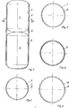
- a fresh water tank 1 sits above a waste water tank 2. Connection elements and pipes are not shown since they are not the subject of the invention.
- the outer walls 3, 4 of both containers 1, 2 are surrounded by a heat pipe 5, which is delimited by an outer wall 6.
- Vertical webs 7 create vertical channels 8 within the heat pipe.
- Corrugated perforated sheets 9 or a fabric web are provided in the heat pipe.
- a corrugated wall 10 on the outer walls 3, 4 of the containers 1, 2 creates a plurality of channels 11.
Landscapes
- Engineering & Computer Science (AREA)
- General Engineering & Computer Science (AREA)
- Thermal Sciences (AREA)
- Mechanical Engineering (AREA)
- Physics & Mathematics (AREA)
- Chemical & Material Sciences (AREA)
- Combustion & Propulsion (AREA)
- Life Sciences & Earth Sciences (AREA)
- Sustainable Development (AREA)
- Heat-Exchange Devices With Radiators And Conduit Assemblies (AREA)
- Thermotherapy And Cooling Therapy Devices (AREA)
- Physical Or Chemical Processes And Apparatus (AREA)
- Hydrogen, Water And Hydrids (AREA)
Description
- Die Erfindung betrifft eine Vorrichtung nach dem Oberbegriff des Patentanspruches 1. Eine Vorrichtung dieser Art ist in der DE-A-2635681 und in der DE-A-2 754 981 beschrieben und dargestellt.
- Ein bevorzugtes Anwendungsgebiet für die genannte Vorrichtung besteht im Bereich der Wärmerückgewinnung aus Abwasser. Damit ein ausreichender Wärmeaustausch erfolgen kann, wird das Abwasser und das Frischwasser durch getrennte Behälter geleitet, die gemäss der DE-A-2 635 681 von Wärmerohren durchsetzt sind. Die Wärmerohre sorgen infolge ihrer Füllung mit einem verdampfbaren Fluid für eine aussergewöhnlich gute Wärmeübertragung. Für die Funktionsfähigkeit der Wärmerohre ist es dabei angebracht, dass der Frischwasserbehälter über dem Abwasserbehälter liegt, da auf diese Weise ein einwandfreies Verdampfen und Kondensieren des Fluids entsprechend einem Schwerkraftwärmerohr garantiert ist. Abwasser darf auf keinen Fall mit Frischwasser, d. h. Trinkwasser vermischt werden. Leckstellen zwischen beiden Behältern müssen deshalb unbedingt ausgeschlossen sein. Im Bereich der Rohrdurchdringung treten hier besondere Abdichtprobleme auf, die nur durch kostenintensive Schweiss- und Fertigungsmethoden verhindert werden können.
- Gemäss der DE-A-2 754 981 wurde auch schon einer der beiden Behälter von einer Verdampferstufe eines Wärmerohres umgeben. Von dort führt ein Rohr zu einer Kondensatorstufe im anderen Behälter. Wanddurchdringungen mit den üblichen Nachteilen einschliesslich der aufwendigen Fertigung werden dabei in Kauf genommen.
- Die Dichtprobleme zwischen beiden Behältern sollen behoben und die Herstellung der gesamten Vorrichtung soll vereinfacht werden.
- Gemäss der Erfindung wird dieses erreicht durch eine Vorrichtung mit dem im Kennzeichen des Patentanspruches 1 genannten Merkmal.
- Das Wärmerohr umgibt beide Behälter und vermeidet Durchdringungen der Trennwand zwischen den Behältern, wodurch jegliche mechanische Arbeiten im Innern der Behälter entfallen. Das Befüllen des äusseren flächigen Wärmerohres ist sehr einfach. Es steht der gesamte Umfang der Behälter als wärmeleitende Oberfläche des Wärmerohres zur Verfügung.
- Die äussere Begrenzung des Wärmerohres bildet eine Wand, die die Behälterwände in geringem Abstand umgibt. Der Zwischenraum, der ein Gewebe oder Lochblech und das verdampfbare Fluid enthält, kann mit vertikalen Stegen versehen sein. Eine Verbesserung des Wärmeüberganges wird durch Sandstrahlen der Aussenflächen beider Behälter erreicht, was zu einer Reinigung und Aufrauhung der Flächen führt.
- Wie an sich bekannt, ist der Frischwasserbehälter über dem Abwasserbehälter angeordnet. Die Flüssigkeit mit der höheren Temperatur liegt dabei unten, so dass das verdampfbare Fluid im Wärmerohr verdampfen und im oberen Frischwasserbereich wieder kondensieren kann. Die zurückgewonnene Wärme kann nicht wieder zurückfliessen. Auf eine Steuerung des Wärmeflusses kann weitgehend verzichtet werden. Eine Zugabe nicht kondensierbarer inerter Gase zum Fluid kann ggf. zur exakten Temperatursteuerung des Frischwasserspeichers benutzt werden.
- Die beigefügte Zeichnung stellt ein Ausführungsbeispiel der Erfindung dar.
- Es zeigt:
- Fig. 1 Eine Vorrichtung im senkrechten Längsschnitt,
- Fig. 2 bis Fig. 5 Den Querschnitt A-A aus Fig. 1 mit unterschiedlicher Gestaltung des Mantels.
- Ein Frischwasserbehälter 1 sitzt über einem Abwasserbehälter 2. Anschlusselemente und Rohrleitungen sind nicht dargestellt, da sie nicht Gegenstand der Erfindung sind. Die Aussenwände 3, 4 beider Behälter 1, 2 sind von einem Wärmerohr 5 umgeben, das durch eine äussere Wand 6 begrenzt ist. Vertikale Stege 7 erzeugen vertikale Kanäle 8 innerhalb des Wärmerohres. Im Wärmerohr sind gewellte Lochbleche 9 bzw. eine Gewebebahn vorgesehen.
- Durch diese Mittel wird die Zirkulation des Fluids innerhalb des Wärmerohres gefördert. Eine Wellwand 10 auf den Aussenwänden 3, 4 der Behälter 1, 2 erzeugt eine Vielzahl von Kanälen 11.
Claims (4)
Priority Applications (1)
| Application Number | Priority Date | Filing Date | Title |
|---|---|---|---|
| AT81101926T ATE10676T1 (de) | 1980-05-16 | 1981-03-16 | Vorrichtung zum waermeaustausch zwischen zwei unterschiedlich temperierten fluessigkeiten. |
Applications Claiming Priority (2)
| Application Number | Priority Date | Filing Date | Title |
|---|---|---|---|
| DE3018800 | 1980-05-16 | ||
| DE19803018800 DE3018800A1 (de) | 1980-05-16 | 1980-05-16 | Vorrichtung zum waermeaustausch zwischen zwei unterschiedlichen temperierten fluessigkeiten |
Publications (2)
| Publication Number | Publication Date |
|---|---|
| EP0040303A1 EP0040303A1 (de) | 1981-11-25 |
| EP0040303B1 true EP0040303B1 (de) | 1984-12-05 |
Family
ID=6102627
Family Applications (1)
| Application Number | Title | Priority Date | Filing Date |
|---|---|---|---|
| EP81101926A Expired EP0040303B1 (de) | 1980-05-16 | 1981-03-16 | Vorrichtung zum Wärmeaustausch zwischen zwei unterschiedlich temperierten Flüssigkeiten |
Country Status (3)
| Country | Link |
|---|---|
| EP (1) | EP0040303B1 (de) |
| AT (1) | ATE10676T1 (de) |
| DE (2) | DE3018800A1 (de) |
Families Citing this family (3)
| Publication number | Priority date | Publication date | Assignee | Title |
|---|---|---|---|---|
| EP2479502B1 (de) * | 2011-01-24 | 2014-09-24 | Torsten Enders | Anlage und Verfahren zur energetischen Nutzung der in Abwassersammelbehältern und/oder Abwasserbehandlungsbehältern vorhandenen Medien |
| US9638471B2 (en) | 2014-11-10 | 2017-05-02 | Hamilton Sundstrand Corporation | Balanced heat exchanger systems and methods |
| US20190191589A1 (en) * | 2017-12-15 | 2019-06-20 | Google Llc | Three-Dimensional Electronic Structure with Integrated Phase-Change Cooling |
Citations (1)
| Publication number | Priority date | Publication date | Assignee | Title |
|---|---|---|---|---|
| FR691648A (fr) * | 1929-05-31 | 1930-10-23 | Platen Munters Refrig Syst Ab | Procédé et dispositifs pour l'élimination de chaleur hors d'une capacité à refroidir |
Family Cites Families (2)
| Publication number | Priority date | Publication date | Assignee | Title |
|---|---|---|---|---|
| DE2635681A1 (de) * | 1976-08-07 | 1978-03-23 | Buderus Ag | Vorrichtung zur waermerueckgewinnung aus abwasser |
| SE406226B (sv) * | 1976-12-10 | 1979-01-29 | Nordstjernan Rederi Ab | Forfarande och anordning for overforande av verme i en fastighet |
-
1980
- 1980-05-16 DE DE19803018800 patent/DE3018800A1/de not_active Withdrawn
-
1981
- 1981-03-16 EP EP81101926A patent/EP0040303B1/de not_active Expired
- 1981-03-16 AT AT81101926T patent/ATE10676T1/de active
- 1981-03-16 DE DE8181101926T patent/DE3167542D1/de not_active Expired
Patent Citations (1)
| Publication number | Priority date | Publication date | Assignee | Title |
|---|---|---|---|---|
| FR691648A (fr) * | 1929-05-31 | 1930-10-23 | Platen Munters Refrig Syst Ab | Procédé et dispositifs pour l'élimination de chaleur hors d'une capacité à refroidir |
Non-Patent Citations (1)
| Title |
|---|
| BROCKHAUS ENZYKLOPÄDIE, 20 Band, 1974, Seite 25 * |
Also Published As
| Publication number | Publication date |
|---|---|
| EP0040303A1 (de) | 1981-11-25 |
| ATE10676T1 (de) | 1984-12-15 |
| DE3018800A1 (de) | 1981-11-26 |
| DE3167542D1 (en) | 1985-01-17 |
Similar Documents
| Publication | Publication Date | Title |
|---|---|---|
| DE2917364C2 (de) | Temperierbarer Tankcontainer | |
| EP0031153B1 (de) | Wärmespeicheranlage zum Einspeichern von Sonnen- oder Abwärme in mehrere Speichertanks | |
| DE2722288A1 (de) | Plattenfoermiger verdampfer | |
| DE3432864A1 (de) | Waermetauscher fuer die physikalische und/oder chemische behandlung einer fluessigkeit | |
| EP0040303A1 (de) | Vorrichtung zum Wärmeaustausch zwischen zwei unterschiedlich temperierten Flüssigkeiten | |
| EP0211240B1 (de) | Vorrichtung zur Nassreinigung von Rauchgas | |
| DE3247392C2 (de) | ||
| EP0190616B1 (de) | Gerät zum Erwärmen von Wasser, insb. Warmwasserheizkessel | |
| DE2400123C3 (de) | Verfahren und Vorrichtung zum Konzentrieren von flüssigen radioaktiven Abfällen | |
| DE2102976C3 (de) | Als Verdampfungskondensator ausgebildeter Plattenwärmetauscher | |
| DE3521725C2 (de) | ||
| DE2754981A1 (de) | Verfahren und vorrichtung zum uebertragen von waerme auf die wasserversorgungs- und/oder die heizeinrichtung eines gebaeudes | |
| DD206511A3 (de) | Duschtasse zur waermerueckgewinnung | |
| DE2431940C2 (de) | Dach- oder Wandelement zur Heizung und/oder Kühlung von Innenräumen | |
| DE692836C (de) | r katalytischer Gasreaktionen | |
| DE2924460A1 (de) | Vorrichtung zum konzentrieren und/oder reinigen von mineralsaeuren | |
| DE3038344C2 (de) | Vorrichtung zum Aufheizen einer Flüssigkeit | |
| DE2606315A1 (de) | Verdampfer mit koaxialen rohren | |
| DE1519715C (de) | Heizkörper für Umlaufverdampfer | |
| DE2654948C2 (de) | Tauch-Wärmeaustauscher | |
| CH476645A (de) | Aus Platten bestehender Tauchkörper in einer mechanisch-biologischen Kläranlage | |
| DE953340C (de) | Behaelter fuer korrodierend wirkende Fluessigkeiten | |
| DE455017C (de) | Dampferzeuger mit mittelbar beheizter Betriebsdampftrommel | |
| DE396220C (de) | Vorrichtung zum kontinuierlichen Verdampfen von Fluessigkeiten | |
| DE2336183C3 (de) | Vorrichtung zum Temperieren und Reinigen von Flüssigkeiten |
Legal Events
| Date | Code | Title | Description |
|---|---|---|---|
| PUAI | Public reference made under article 153(3) epc to a published international application that has entered the european phase |
Free format text: ORIGINAL CODE: 0009012 |
|
| AK | Designated contracting states |
Designated state(s): AT BE CH DE FR GB IT NL SE |
|
| 17P | Request for examination filed |
Effective date: 19811020 |
|
| GRAA | (expected) grant |
Free format text: ORIGINAL CODE: 0009210 |
|
| AK | Designated contracting states |
Designated state(s): AT BE CH DE FR GB IT LI NL SE |
|
| PG25 | Lapsed in a contracting state [announced via postgrant information from national office to epo] |
Ref country code: SE Effective date: 19841205 Ref country code: NL Effective date: 19841205 Ref country code: IT Free format text: LAPSE BECAUSE OF FAILURE TO SUBMIT A TRANSLATION OF THE DESCRIPTION OR TO PAY THE FEE WITHIN THE PRESCRIBED TIME-LIMIT;WARNING: LAPSES OF ITALIAN PATENTS WITH EFFECTIVE DATE BEFORE 2007 MAY HAVE OCCURRED AT ANY TIME BEFORE 2007. THE CORRECT EFFECTIVE DATE MAY BE DIFFERENT FROM THE ONE RECORDED. Effective date: 19841205 Ref country code: FR Free format text: THE PATENT HAS BEEN ANNULLED BY A DECISION OF A NATIONAL AUTHORITY Effective date: 19841205 Ref country code: BE Effective date: 19841205 |
|
| REF | Corresponds to: |
Ref document number: 10676 Country of ref document: AT Date of ref document: 19841215 Kind code of ref document: T |
|
| REF | Corresponds to: |
Ref document number: 3167542 Country of ref document: DE Date of ref document: 19850117 |
|
| PG25 | Lapsed in a contracting state [announced via postgrant information from national office to epo] |
Ref country code: AT Effective date: 19850316 |
|
| PG25 | Lapsed in a contracting state [announced via postgrant information from national office to epo] |
Ref country code: LI Effective date: 19850331 Ref country code: CH Effective date: 19850331 |
|
| NLV1 | Nl: lapsed or annulled due to failure to fulfill the requirements of art. 29p and 29m of the patents act | ||
| EN | Fr: translation not filed | ||
| PLBE | No opposition filed within time limit |
Free format text: ORIGINAL CODE: 0009261 |
|
| STAA | Information on the status of an ep patent application or granted ep patent |
Free format text: STATUS: NO OPPOSITION FILED WITHIN TIME LIMIT |
|
| GBPC | Gb: european patent ceased through non-payment of renewal fee | ||
| REG | Reference to a national code |
Ref country code: CH Ref legal event code: PL |
|
| 26N | No opposition filed | ||
| PG25 | Lapsed in a contracting state [announced via postgrant information from national office to epo] |
Ref country code: DE Effective date: 19861202 |
|
| PG25 | Lapsed in a contracting state [announced via postgrant information from national office to epo] |
Ref country code: GB Effective date: 19881118 |