EP0036908B1 - Notlaufring für Fahrzeug-Luftreifen - Google Patents
Notlaufring für Fahrzeug-Luftreifen Download PDFInfo
- Publication number
- EP0036908B1 EP0036908B1 EP80107586A EP80107586A EP0036908B1 EP 0036908 B1 EP0036908 B1 EP 0036908B1 EP 80107586 A EP80107586 A EP 80107586A EP 80107586 A EP80107586 A EP 80107586A EP 0036908 B1 EP0036908 B1 EP 0036908B1
- Authority
- EP
- European Patent Office
- Prior art keywords
- lip
- lubricant
- safety ring
- continuous
- closure
- Prior art date
- Legal status (The legal status is an assumption and is not a legal conclusion. Google has not performed a legal analysis and makes no representation as to the accuracy of the status listed.)
- Expired
Links
- 239000000314 lubricant Substances 0.000 claims description 37
- 238000007789 sealing Methods 0.000 claims description 32
- 229920001971 elastomer Polymers 0.000 claims description 12
- 239000000806 elastomer Substances 0.000 claims description 9
- 210000002105 tongue Anatomy 0.000 claims description 8
- 238000004519 manufacturing process Methods 0.000 claims description 4
- 238000004073 vulcanization Methods 0.000 claims description 3
- 239000011324 bead Substances 0.000 claims description 2
- 238000005461 lubrication Methods 0.000 claims description 2
- 239000000463 material Substances 0.000 claims description 2
- 230000006835 compression Effects 0.000 claims 1
- 238000007906 compression Methods 0.000 claims 1
- 239000011888 foil Substances 0.000 claims 1
- DOSMHBDKKKMIEF-UHFFFAOYSA-N 2-[3-(diethylamino)-6-diethylazaniumylidenexanthen-9-yl]-5-[3-[3-[4-(1-methylindol-3-yl)-2,5-dioxopyrrol-3-yl]indol-1-yl]propylsulfamoyl]benzenesulfonate Chemical compound C1=CC(=[N+](CC)CC)C=C2OC3=CC(N(CC)CC)=CC=C3C(C=3C(=CC(=CC=3)S(=O)(=O)NCCCN3C4=CC=CC=C4C(C=4C(NC(=O)C=4C=4C5=CC=CC=C5N(C)C=4)=O)=C3)S([O-])(=O)=O)=C21 DOSMHBDKKKMIEF-UHFFFAOYSA-N 0.000 description 4
- 230000000694 effects Effects 0.000 description 3
- 239000004604 Blowing Agent Substances 0.000 description 2
- 230000036316 preload Effects 0.000 description 2
- 235000001674 Agaricus brunnescens Nutrition 0.000 description 1
- 239000004698 Polyethylene Substances 0.000 description 1
- 229910000831 Steel Inorganic materials 0.000 description 1
- 239000000853 adhesive Substances 0.000 description 1
- 230000001070 adhesive effect Effects 0.000 description 1
- 230000000254 damaging effect Effects 0.000 description 1
- 235000014113 dietary fatty acids Nutrition 0.000 description 1
- 239000013013 elastic material Substances 0.000 description 1
- 239000013536 elastomeric material Substances 0.000 description 1
- 229930195729 fatty acid Natural products 0.000 description 1
- 239000000194 fatty acid Substances 0.000 description 1
- 150000004665 fatty acids Chemical class 0.000 description 1
- 238000001746 injection moulding Methods 0.000 description 1
- 238000009434 installation Methods 0.000 description 1
- 230000007774 longterm Effects 0.000 description 1
- -1 polyethylene Polymers 0.000 description 1
- 229920000573 polyethylene Polymers 0.000 description 1
- 229920000151 polyglycol Polymers 0.000 description 1
- 239000010695 polyglycol Substances 0.000 description 1
- 230000000284 resting effect Effects 0.000 description 1
- 150000003839 salts Chemical class 0.000 description 1
- 239000007787 solid Substances 0.000 description 1
- 239000010959 steel Substances 0.000 description 1
- 239000000126 substance Substances 0.000 description 1
- 230000008961 swelling Effects 0.000 description 1
Images
Classifications
-
- B—PERFORMING OPERATIONS; TRANSPORTING
- B60—VEHICLES IN GENERAL
- B60C—VEHICLE TYRES; TYRE INFLATION; TYRE CHANGING; CONNECTING VALVES TO INFLATABLE ELASTIC BODIES IN GENERAL; DEVICES OR ARRANGEMENTS RELATED TO TYRES
- B60C17/00—Tyres characterised by means enabling restricted operation in damaged or deflated condition; Accessories therefor
- B60C17/10—Internal lubrication
-
- B—PERFORMING OPERATIONS; TRANSPORTING
- B60—VEHICLES IN GENERAL
- B60C—VEHICLE TYRES; TYRE INFLATION; TYRE CHANGING; CONNECTING VALVES TO INFLATABLE ELASTIC BODIES IN GENERAL; DEVICES OR ARRANGEMENTS RELATED TO TYRES
- B60C17/00—Tyres characterised by means enabling restricted operation in damaged or deflated condition; Accessories therefor
- B60C17/04—Tyres characterised by means enabling restricted operation in damaged or deflated condition; Accessories therefor utilising additional non-inflatable supports which become load-supporting in emergency
- B60C17/06—Tyres characterised by means enabling restricted operation in damaged or deflated condition; Accessories therefor utilising additional non-inflatable supports which become load-supporting in emergency resilient
- B60C2017/068—Tyres characterised by means enabling restricted operation in damaged or deflated condition; Accessories therefor utilising additional non-inflatable supports which become load-supporting in emergency resilient comprising springs, e.g. helical springs
-
- Y—GENERAL TAGGING OF NEW TECHNOLOGICAL DEVELOPMENTS; GENERAL TAGGING OF CROSS-SECTIONAL TECHNOLOGIES SPANNING OVER SEVERAL SECTIONS OF THE IPC; TECHNICAL SUBJECTS COVERED BY FORMER USPC CROSS-REFERENCE ART COLLECTIONS [XRACs] AND DIGESTS
- Y10—TECHNICAL SUBJECTS COVERED BY FORMER USPC
- Y10T—TECHNICAL SUBJECTS COVERED BY FORMER US CLASSIFICATION
- Y10T152/00—Resilient tires and wheels
- Y10T152/10—Tires, resilient
- Y10T152/10495—Pneumatic tire or inner tube
- Y10T152/10738—Pneumatic tire or inner tube with means to protect tire from rim
Definitions
- the invention relates to an emergency running ring made of rubber or other elastomers in tubeless pneumatic tires for motor vehicles mounted on flat-bed rims, which rests on the rim with its foot part taking up the space between the tire beads and at least one circumferential lubricant on at least one of its sides facing the pneumatic tire Containing cavity, which can be closed by means of a sealing lip and a counter lip assigned to it and is kept closed when the pneumatic tire is intact by its internal pressure and by an axial preload, and which has at least one circumferential undercut, the undercut forming, elastically resilient tongues serve as lever arms , which are pressed as a result of air pressure loss in the pneumatic tire by the pressure of the tire cover on the run-flat ring towards the bottom of the undercut and thereby the locking lips connected to them as lifting arms in transfer an opening position releasing the lubricant, so that it reaches for lubrication between the contacting surfaces of the pneumatic tire and the emergency running ring.
- a run-flat ring of the type mentioned is known from EP-A-0011 698 falling under Article 54 paragraph 3.
- the lubricant-containing cavity is formed in that a groove embedded in the flank of the run-flat ring rests with its open side on the inner wall of the tire and is sealed against the inner space of the tire by a sealing lip which is pressed against the inner wall of the tire by the air pressure in the tire becomes.
- the lubricant-filled cavities are arranged between the outside and the central circumferential undercut of the run-flat ring, the sealing lips, thanks to a lateral preload generated when the run-flat ring is installed in a pneumatic tire, in cooperation with the edge zones of the run-flat ring, one each from the cavity Seal the lubricant outlet channel leading into the tire interior.
- the functionality of the emergency running ring with regard to the opening of the lubricant-filled cavities is ensured by leverage when emergency running occurs.
- the invention has for its object to provide temporary sealing of the lubricant-filled cavities seals that are more reliable than the previously known cavity closures and which are also easy to manufacture and contribute to ensuring easy installation of the emergency running ring.
- the main advantage of the invention is that it ensures that the lubricant is stored securely until the emergency operation begins. Further advantages of the invention are shown in the following description of individual embodiments.
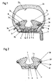
- the emergency running ring 3 shows an emergency running ring 3, which is inserted into a tubeless pneumatic tire 2 and is made of rubber or other elastomers, the basic structure of which is known from EP-A-0 011 698.
- the pneumatic tire 2 and the run-flat ring 3 are mounted on a flat-bed rim 1.
- the emergency running ring 3 has a foot part 3a and an upper part 3b adjoining this.
- the foot part 3a is reinforced by two or more steel wire bundles 4, which provide the emergency running ring 3 with a firm fit on the flatbed rim 1.
- the foot part 3a can consist of an elastomer which is harder than that used for the upper part 3b.
- the foot part 3a On its underside, the foot part 3a has a centrally arranged, circumferential groove 5 which is open towards the flat-bed rim 1 and from which a plurality of through-channels 6 distributed over the circumference of the ring lead to the interior of the tire.
- This channel system ensures that air inflows from the valve into the tire interior when the tire 2 is inflated.
- the upper part 3b rises slightly towards the center and has a centrally arranged, circumferential undercut 7, the contour of which resembles a mushroom standing on its head.
- This undercut 7 forms two elastically resilient tongues 3c, each of which merges to the side into a sealing lip 3d.
- Each sealing lip 3d lies against a counter lip 3e and encloses with it a circumferential cavity 8 filled with a lubricant X. Due to the inflation pressure of the pneumatic tire 2, the sealing lips 3d are pressed firmly against the sealing lips 3e resting on the inside of the pneumatic tire 2. If the pneumatic tire 2 loses air due to external influences, the tire cover 2a lowers down until it hits the run-flat ring 3 with its inside 2b.
- the tire cover 2a which is under the axle pressure of the vehicle, presses the two tongues 3c of the run-flat ring 3 into the undercut 7, as a result of which leverage is exerted on the locking lips 3d in such a way that they are raised and that at operating temperatures of the pneumatic tire 2 of over Release 40 ° C liquefying lubricant X, which gets between the contacting surfaces of pneumatic tires 2 and run-flat ring 3 and significantly reduces the friction occurring between the contacting surfaces.
- Substances that do not have a swelling or any other damaging effect on elastomers, such as polyglycols or salts of fatty acids, are to be used as lubricants.
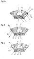
- Fig. 2 shows a first embodiment of the emergency running ring according to the invention.
- the sealing lip 3d which together with the counter lip 3e closes the cavity 8 intended for receiving a lubricant until the emergency operation occurs, is provided on its side facing the counter lip 3e with three tooth-shaped projections 3f.
- These projections 3f have the effect that the closing surfaces of the two sealing lips 3d and 3e, which are pressed firmly against one another by the internal tire pressure, nestle well against one another, as a result of which the cavity 8 is sealed well over the long term.
- the same sealing effect would also be achieved if, instead of the sealing lip 3d, the counter lip 3e were provided with tooth-shaped projections.
- a reliable closure of the cavity 8 is achieved according to the invention in that the closure lip 3r has a toothed closing surface 3s which engages in a staggered arrangement of correspondingly toothed closing surface 3t of the counter lip 3u.
- FIG. 3 an emergency running ring is shown, in which the sealing lip 3g according to the invention has a hook-shaped end which engages in a slightly undercut recess of the counter lip 3h, as long as a lateral pressure is exerted thereon, as is the case after the emergency running ring has been installed the case is.
- the sealing lip 3g is released from the engagement with the counter lip 3h and the lubricant stored in the cavity 8 is released due to the mechanical effects that then occur.
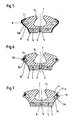
- the embodiment according to FIG. 4 discloses a further possibility of keeping the lubricant under lock and key as long as the air inflation pressure necessary for its normal operation is present in the tire.
- the sealing lip 3i and the counter lip 3k are connected to one another along their free edges by a thin skin which is produced during the production of the emergency running ring by vulcanizing the base material and which serves as a predetermined breaking point.
- the locking lip 3i is moved upward from its closed position by the lever arm force acting on the associated tongue 3c, as a result of which the skin is torn open and the lubricant can emerge from the cavity 8.
- the cavity 8 created with the blank production of the emergency running ring in the hollow-strand injection molding process is maintained in the vulcanization phase, for example, by means of an added blowing agent. After vulcanization, the blowing agent is released and the lubricant is poured in.
- the sealing lip 31 and the counter lip 3m are shaped in such a way that when the emergency running ring is not installed, there is only a small opening gap between these sealing lips and the cavity 8.
- This opening gap is covered from the outside by a thin, vulcanized, circumferential elastomer strip 9, which can be attached, for example, by means of a cold vulcanizing adhesive.
- the elastomer strip 9 is torn open due to the known lever action.
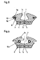
- an aid is used to seal the cavity 8, namely a hose 10 made of elastic material, the ends of which are connected to one another and the length of which corresponds to the circumference of the circumferential cavity 8.
- This hose 10 is loosely inserted into the cavity 8 before the emergency running ring is installed and, if appropriate, additionally glued to the sealing lip 3n or to the counter lip 3o.
- the counter lip 3o pressed against the hose 10 during assembly closes the cavity 8 tightly with the aid of the hose 10.
- a strand of solid elastomeric material can also be used.
- the hose 11 shown in FIG. 7 has a circumferential or interrupted web 11a, which engages in a circumferential recess of the sealing lip 3n corresponding to the web and thus the hose 11 has a fixed position in the opening gap of the cavity 8 backs up.
- the counter lip 3o is pressed against the hose 11 sealing the cavity 8 during assembly of the emergency running ring.
- the web 11a extending from the hose 11 can also be anchored in a recess located in the counter lip 3o.
- the emergency running ring In the emergency running ring according to FIG. 8, it is provided to accommodate the lubricant in a hose 12, for example made of polyethylene, or in suitably designed hose pieces and to insert this hose 12 or these hose pieces into the cavity 8 which can be closed by the sealing lip 3p and the counter lip 3q.
- the sealing lip 3p which is under side pressure, lies firmly against the counter lip 3q, so that the lubricant-filled hose 12 is securely enclosed in the cavity 8.
- the cavity 8 When emergency running occurs, the cavity 8 is opened and the hose 12 is thrown out of the cavity 8 into the tire interior, where it is destroyed by friction, crushing and heat between the tire cover and the emergency running ring and releases the lubricant.
- the tongues 3c forming the central undercut 7 are undercut towards the two sides of the emergency running ring 3 in such a way that a groove 12a is formed in each case.
- a hose 12 filled with a lubricant is clamped in each groove 12a and is encompassed by the groove wall except for a small part of its surface.
Landscapes
- Engineering & Computer Science (AREA)
- Mechanical Engineering (AREA)
- Tires In General (AREA)
Applications Claiming Priority (2)
| Application Number | Priority Date | Filing Date | Title |
|---|---|---|---|
| DE3008972 | 1980-03-08 | ||
| DE3008972A DE3008972C2 (de) | 1980-03-08 | 1980-03-08 | Notlaufring für Fahrzeug-Luftreifen |
Publications (2)
| Publication Number | Publication Date |
|---|---|
| EP0036908A1 EP0036908A1 (de) | 1981-10-07 |
| EP0036908B1 true EP0036908B1 (de) | 1984-06-27 |
Family
ID=6096636
Family Applications (1)
| Application Number | Title | Priority Date | Filing Date |
|---|---|---|---|
| EP80107586A Expired EP0036908B1 (de) | 1980-03-08 | 1980-12-04 | Notlaufring für Fahrzeug-Luftreifen |
Country Status (5)
| Country | Link |
|---|---|
| US (1) | US4371024A (es) |
| EP (1) | EP0036908B1 (es) |
| JP (1) | JPS56128206A (es) |
| CA (1) | CA1153676A (es) |
| DE (1) | DE3008972C2 (es) |
Families Citing this family (17)
| Publication number | Priority date | Publication date | Assignee | Title |
|---|---|---|---|---|
| FR2516868A1 (fr) * | 1981-11-20 | 1983-05-27 | Michelin & Cie | Support interne pour s'opposer a l'aplatissement d'un pneumatique |
| FR2519912A1 (fr) * | 1982-01-15 | 1983-07-22 | Hutchinson | Dispositif de montage d'un pneu avec manchon de verrouillage |
| DE3331143A1 (de) * | 1983-08-30 | 1985-03-21 | Vorwerk & Sohn Gmbh & Co Kg, 5600 Wuppertal | Notlaufring fuer schlauchlose luftreifen von kraftfahrzeugen |
| DE3332524A1 (de) * | 1983-09-09 | 1985-03-28 | Vorwerk & Sohn Gmbh & Co Kg, 5600 Wuppertal | Notlaufring fuer fahrzeugreifen |
| EP0159274B2 (fr) * | 1984-04-19 | 1993-01-20 | Hutchinson | Dispositif de verrouillage à fonctions multiples pour le montage d'une enveloppe de pneumatique sur une jante de roue |
| FR2563164B1 (fr) * | 1984-04-19 | 1986-09-19 | Hutchinson | Dispositif de verrouillage a fonctions multiples pour le montage d'une enveloppe de pneumatique sur une jante de roue |
| FR2567815B2 (fr) * | 1984-04-19 | 1987-02-27 | Hutchinson | Dispositif de verrouillage a fonctions multiples pour le montage d'une enveloppe de pneumatique sur une jante de roue |
| EP0707985A3 (en) * | 1994-10-21 | 1997-03-05 | Oks Lili Feld | Tire holding device |
| US5634506A (en) * | 1995-05-01 | 1997-06-03 | Trinc, Tire & Rim, Inc. | Composite wheel |
| US5837072A (en) * | 1996-08-22 | 1998-11-17 | Fukunaga Engineering Co., Ltd. | Solid tire |
| DE19825311C1 (de) * | 1998-06-05 | 2000-02-24 | Continental Ag | Fahrzeugrad mit einem Notlaufstützkörper |
| EP1227943B1 (fr) * | 1999-10-19 | 2004-06-02 | Société de Technologie Michelin | Dispositif d'obturation d'un reservoir de lubrifiant et methode de lubrification de la cavite interne d'un pneumatique |
| FR2811329A1 (fr) * | 2000-07-07 | 2002-01-11 | Michelin Soc Tech | Composition lubrifiante pour interface enveloppe de pneumatique/appui de securite en roulage a plat |
| FR2841825B1 (fr) * | 2002-07-08 | 2004-08-27 | Michelin Soc Tech | Jante de roue constituee de deux structures assemblees |
| CN105522872A (zh) * | 2015-12-11 | 2016-04-27 | 向兵 | 分隔式防爆车轮 |
| DE102019109890B4 (de) | 2019-04-15 | 2021-09-23 | Krauss-Maffei Wegmann Gmbh & Co. Kg | Notlaufelement für Gefechtsreifen |
| KR102181821B1 (ko) * | 2019-09-02 | 2020-11-23 | 이영기 | 타이어용 인서트 |
Citations (4)
| Publication number | Priority date | Publication date | Assignee | Title |
|---|---|---|---|---|
| FR2095396A1 (es) * | 1970-06-20 | 1972-02-11 | Dunlop Holdings Ltd | |
| FR2178114A2 (en) * | 1971-07-30 | 1973-11-09 | Pirelli | Tyres which avoid overheating when flat - using lubricant -filled recesses |
| FR2185515A1 (es) * | 1972-05-23 | 1974-01-04 | Dunlop Ltd | |
| US4091854A (en) * | 1970-06-20 | 1978-05-30 | Dunlop Holdings Limited | Tire and wheel assemblies |
Family Cites Families (15)
| Publication number | Priority date | Publication date | Assignee | Title |
|---|---|---|---|---|
| US3814158A (en) * | 1970-04-03 | 1974-06-04 | Firestone Tire & Rubber Co | Run flat device for tires |
| GB1359461A (en) * | 1970-06-20 | 1974-07-10 | Dunlop Ltd | Pneumatic tyre and wheel assemblies |
| BR7107184D0 (pt) * | 1971-10-27 | 1973-08-16 | Novatracao Artefatos De Borrac | Aperfeicoamentos em pneumatico a prova de bala provido com camada interna de borracha e anel separador |
| GB1427713A (en) * | 1972-03-11 | 1976-03-10 | Dunlop Ltd | Pneumatic tyre and wheel assemblies |
| GB1415504A (en) * | 1972-05-26 | 1975-11-26 | Apv Paralec Ltd | Coreless induction furnace refining and melting apparatus and processes |
| US3872907A (en) * | 1973-10-01 | 1975-03-25 | Goodyear Tire & Rubber | Safety support device for pneumatic tires |
| IT1035798B (it) * | 1974-07-31 | 1979-10-20 | Ford Motor Co | Perfezionamento nei complessi ruota pneumatico in grado dias sicurare la marcia in caso di sgonfiatura |
| FR2283789A1 (fr) * | 1974-09-03 | 1976-04-02 | Hutchinson Mapa | Pneumatique de securite pour roue de vehicule |
| US3942573A (en) * | 1975-01-30 | 1976-03-09 | The Firestone Tire & Rubber Company | Tire lubricating device |
| US3990492A (en) * | 1975-03-31 | 1976-11-09 | The Goodyear Tire & Rubber Company | Fluid dispensing apparatus for tire wheel assembly |
| GB1572041A (en) * | 1976-03-25 | 1980-07-23 | Ford Motor Co | Runflat system for a vehicle wheel |
| US4054168A (en) * | 1976-04-15 | 1977-10-18 | The Goodyear Tire & Rubber Company | Fluid dispensing apparatus for tire wheel assembly |
| DE2817394A1 (de) * | 1977-05-02 | 1978-11-16 | Ford Werke Ag | Stuetzteil fuer die laufdecke eines fahrzeugreifens |
| DE2851187C2 (de) * | 1978-11-27 | 1983-10-20 | Vorwerk & Sohn Gmbh & Co Kg, 5600 Wuppertal | Notlaufring für Fahrzeug - Luftreifen |
| US4263953A (en) * | 1979-01-15 | 1981-04-28 | Uniroyal, Inc. | Self-lubricating pneumatic insert for a pneumatic tire |
-
1980
- 1980-03-08 DE DE3008972A patent/DE3008972C2/de not_active Expired
- 1980-12-04 EP EP80107586A patent/EP0036908B1/de not_active Expired
-
1981
- 1981-02-10 US US06/233,136 patent/US4371024A/en not_active Expired - Fee Related
- 1981-02-17 JP JP2099181A patent/JPS56128206A/ja active Granted
- 1981-03-06 CA CA000372514A patent/CA1153676A/en not_active Expired
Patent Citations (4)
| Publication number | Priority date | Publication date | Assignee | Title |
|---|---|---|---|---|
| FR2095396A1 (es) * | 1970-06-20 | 1972-02-11 | Dunlop Holdings Ltd | |
| US4091854A (en) * | 1970-06-20 | 1978-05-30 | Dunlop Holdings Limited | Tire and wheel assemblies |
| FR2178114A2 (en) * | 1971-07-30 | 1973-11-09 | Pirelli | Tyres which avoid overheating when flat - using lubricant -filled recesses |
| FR2185515A1 (es) * | 1972-05-23 | 1974-01-04 | Dunlop Ltd |
Also Published As
| Publication number | Publication date |
|---|---|
| JPS56128206A (en) | 1981-10-07 |
| DE3008972A1 (de) | 1981-09-24 |
| DE3008972C2 (de) | 1984-08-30 |
| JPS6111801B2 (es) | 1986-04-04 |
| CA1153676A (en) | 1983-09-13 |
| EP0036908A1 (de) | 1981-10-07 |
| US4371024A (en) | 1983-02-01 |
Similar Documents
| Publication | Publication Date | Title |
|---|---|---|
| EP0036908B1 (de) | Notlaufring für Fahrzeug-Luftreifen | |
| EP0011698B1 (de) | Notlaufring für Fahrzeug-Luftreifen | |
| EP0774333B1 (de) | Reifenvulkanisationsform mit Entlüftung | |
| DE3878397T2 (de) | Felge mit wulsteinlage zum fahren im drucklosen zustand. | |
| DE8032334U1 (de) | Reifen/felgenanordnung | |
| DE20316995U1 (de) | Felgenboden, der zum Ausstatten einer Felge eines Fahrrads vorgesehen ist | |
| DE102004055892A1 (de) | Speichenradfelge für Schlauchlosreifen | |
| DE69302665T2 (de) | Verbesserte ringförmige Notlaufeinrichtung | |
| DE2445787A1 (de) | Wagenradanordnung | |
| EP0134035B1 (de) | Notlaufring für schlauchlose Luftreifen von Kraftfahrzeugen | |
| DE887013C (de) | Anordnung eines schlauchlosen Luftreifens mit Wuelsten auf einer Radfelge | |
| EP2389296B1 (de) | Schlauchsystem für reifen | |
| DE3008698C2 (es) | ||
| EP3463837B1 (de) | Entlüftungseinheit für eine vulkanisationsform eines fahrzeugluftreifens | |
| DE602005000508T2 (de) | Luftreifen | |
| DE3321978C2 (es) | ||
| DE3439949A1 (de) | Stuetzring fuer schlauchlose luftreifen fuer fahrzeugraeder | |
| DE3704830A1 (de) | Fahrzeugrad | |
| DE2809786A1 (de) | Einheitlicher notlauf- und wulstsicherungseinsatz mit verriegelungseinrichtung fuer luftreifen | |
| DE2321345B2 (de) | Radfelge fuer schlauchlose reifen | |
| DE3332524A1 (de) | Notlaufring fuer fahrzeugreifen | |
| DE8432017U1 (de) | Stützring für schlauchlose Luftreifen für Fahrzeugräder | |
| DE2530836A1 (de) | Rad, insbesondere fuer kraftfahrzeuge | |
| DE3231012A1 (de) | Fahrzeugrad | |
| DE2506767A1 (de) | Fahrzeugrad |
Legal Events
| Date | Code | Title | Description |
|---|---|---|---|
| PUAI | Public reference made under article 153(3) epc to a published international application that has entered the european phase |
Free format text: ORIGINAL CODE: 0009012 |
|
| AK | Designated contracting states |
Designated state(s): BE FR GB IT LU NL SE |
|
| 17P | Request for examination filed |
Effective date: 19810915 |
|
| ITF | It: translation for a ep patent filed | ||
| GRAA | (expected) grant |
Free format text: ORIGINAL CODE: 0009210 |
|
| AK | Designated contracting states |
Designated state(s): BE FR GB IT LU NL SE |
|
| ET | Fr: translation filed | ||
| PG25 | Lapsed in a contracting state [announced via postgrant information from national office to epo] |
Ref country code: LU Free format text: LAPSE BECAUSE OF NON-PAYMENT OF DUE FEES Effective date: 19841231 |
|
| PLBE | No opposition filed within time limit |
Free format text: ORIGINAL CODE: 0009261 |
|
| STAA | Information on the status of an ep patent application or granted ep patent |
Free format text: STATUS: NO OPPOSITION FILED WITHIN TIME LIMIT |
|
| 26N | No opposition filed | ||
| PGFP | Annual fee paid to national office [announced via postgrant information from national office to epo] |
Ref country code: LU Payment date: 19891011 Year of fee payment: 10 |
|
| PGFP | Annual fee paid to national office [announced via postgrant information from national office to epo] |
Ref country code: SE Payment date: 19891012 Year of fee payment: 10 |
|
| PGFP | Annual fee paid to national office [announced via postgrant information from national office to epo] |
Ref country code: BE Payment date: 19891206 Year of fee payment: 10 |
|
| PGFP | Annual fee paid to national office [announced via postgrant information from national office to epo] |
Ref country code: NL Payment date: 19891231 Year of fee payment: 10 |
|
| PGFP | Annual fee paid to national office [announced via postgrant information from national office to epo] |
Ref country code: FR Payment date: 19901128 Year of fee payment: 11 |
|
| PG25 | Lapsed in a contracting state [announced via postgrant information from national office to epo] |
Ref country code: SE Effective date: 19901205 |
|
| ITTA | It: last paid annual fee | ||
| PG25 | Lapsed in a contracting state [announced via postgrant information from national office to epo] |
Ref country code: BE Effective date: 19901231 |
|
| BERE | Be: lapsed |
Owner name: VORWERK & SOHN G.M.B.H. & CO. K.G. Effective date: 19901231 |
|
| PG25 | Lapsed in a contracting state [announced via postgrant information from national office to epo] |
Ref country code: NL Effective date: 19910701 |
|
| NLV4 | Nl: lapsed or anulled due to non-payment of the annual fee | ||
| PGFP | Annual fee paid to national office [announced via postgrant information from national office to epo] |
Ref country code: GB Payment date: 19911122 Year of fee payment: 12 |
|
| PG25 | Lapsed in a contracting state [announced via postgrant information from national office to epo] |
Ref country code: FR Effective date: 19920831 |
|
| REG | Reference to a national code |
Ref country code: FR Ref legal event code: ST |
|
| PG25 | Lapsed in a contracting state [announced via postgrant information from national office to epo] |
Ref country code: GB Effective date: 19921204 |
|
| GBPC | Gb: european patent ceased through non-payment of renewal fee |
Effective date: 19921204 |
|
| EUG | Se: european patent has lapsed |
Ref document number: 80107586.2 Effective date: 19910910 |