EP0036633B1 - Verfahren zur Herstellung elektrisch beheizter Matten - Google Patents
Verfahren zur Herstellung elektrisch beheizter Matten Download PDFInfo
- Publication number
- EP0036633B1 EP0036633B1 EP81102034A EP81102034A EP0036633B1 EP 0036633 B1 EP0036633 B1 EP 0036633B1 EP 81102034 A EP81102034 A EP 81102034A EP 81102034 A EP81102034 A EP 81102034A EP 0036633 B1 EP0036633 B1 EP 0036633B1
- Authority
- EP
- European Patent Office
- Prior art keywords
- foil
- insulating film
- metal foil
- composite
- resistance
- Prior art date
- Legal status (The legal status is an assumption and is not a legal conclusion. Google has not performed a legal analysis and makes no representation as to the accuracy of the status listed.)
- Expired
Links
Images
Classifications
-
- B—PERFORMING OPERATIONS; TRANSPORTING
- B29—WORKING OF PLASTICS; WORKING OF SUBSTANCES IN A PLASTIC STATE IN GENERAL
- B29C—SHAPING OR JOINING OF PLASTICS; SHAPING OF MATERIAL IN A PLASTIC STATE, NOT OTHERWISE PROVIDED FOR; AFTER-TREATMENT OF THE SHAPED PRODUCTS, e.g. REPAIRING
- B29C70/00—Shaping composites, i.e. plastics material comprising reinforcements, fillers or preformed parts, e.g. inserts
- B29C70/68—Shaping composites, i.e. plastics material comprising reinforcements, fillers or preformed parts, e.g. inserts by incorporating or moulding on preformed parts, e.g. inserts or layers, e.g. foam blocks
- B29C70/685—Shaping composites, i.e. plastics material comprising reinforcements, fillers or preformed parts, e.g. inserts by incorporating or moulding on preformed parts, e.g. inserts or layers, e.g. foam blocks by laminating inserts between two plastic films or plates
- B29C70/687—Shaping composites, i.e. plastics material comprising reinforcements, fillers or preformed parts, e.g. inserts by incorporating or moulding on preformed parts, e.g. inserts or layers, e.g. foam blocks by laminating inserts between two plastic films or plates the inserts being oriented, e.g. nets or meshes
-
- H—ELECTRICITY
- H05—ELECTRIC TECHNIQUES NOT OTHERWISE PROVIDED FOR
- H05B—ELECTRIC HEATING; ELECTRIC LIGHT SOURCES NOT OTHERWISE PROVIDED FOR; CIRCUIT ARRANGEMENTS FOR ELECTRIC LIGHT SOURCES, IN GENERAL
- H05B3/00—Ohmic-resistance heating
- H05B3/20—Heating elements having extended surface area substantially in a two-dimensional [2D] plane, e.g. plate-heater
- H05B3/34—Heating elements having extended surface area substantially in a two-dimensional [2D] plane, e.g. plate-heater flexible, e.g. heating nets or webs
- H05B3/36—Heating elements having extended surface area substantially in a two-dimensional [2D] plane, e.g. plate-heater flexible, e.g. heating nets or webs heating conductor embedded in insulating material
-
- H—ELECTRICITY
- H05—ELECTRIC TECHNIQUES NOT OTHERWISE PROVIDED FOR
- H05B—ELECTRIC HEATING; ELECTRIC LIGHT SOURCES NOT OTHERWISE PROVIDED FOR; CIRCUIT ARRANGEMENTS FOR ELECTRIC LIGHT SOURCES, IN GENERAL
- H05B2203/00—Aspects relating to Ohmic resistive heating covered by group H05B3/00
- H05B2203/002—Heaters using a particular layout for the resistive material or resistive elements
- H05B2203/003—Heaters using a particular layout for the resistive material or resistive elements using serpentine layout
-
- H—ELECTRICITY
- H05—ELECTRIC TECHNIQUES NOT OTHERWISE PROVIDED FOR
- H05B—ELECTRIC HEATING; ELECTRIC LIGHT SOURCES NOT OTHERWISE PROVIDED FOR; CIRCUIT ARRANGEMENTS FOR ELECTRIC LIGHT SOURCES, IN GENERAL
- H05B2203/00—Aspects relating to Ohmic resistive heating covered by group H05B3/00
- H05B2203/002—Heaters using a particular layout for the resistive material or resistive elements
- H05B2203/004—Heaters using a particular layout for the resistive material or resistive elements using zigzag layout
-
- H—ELECTRICITY
- H05—ELECTRIC TECHNIQUES NOT OTHERWISE PROVIDED FOR
- H05B—ELECTRIC HEATING; ELECTRIC LIGHT SOURCES NOT OTHERWISE PROVIDED FOR; CIRCUIT ARRANGEMENTS FOR ELECTRIC LIGHT SOURCES, IN GENERAL
- H05B2203/00—Aspects relating to Ohmic resistive heating covered by group H05B3/00
- H05B2203/011—Heaters using laterally extending conductive material as connecting means
-
- H—ELECTRICITY
- H05—ELECTRIC TECHNIQUES NOT OTHERWISE PROVIDED FOR
- H05B—ELECTRIC HEATING; ELECTRIC LIGHT SOURCES NOT OTHERWISE PROVIDED FOR; CIRCUIT ARRANGEMENTS FOR ELECTRIC LIGHT SOURCES, IN GENERAL
- H05B2203/00—Aspects relating to Ohmic resistive heating covered by group H05B3/00
- H05B2203/014—Heaters using resistive wires or cables not provided for in H05B3/54
-
- H—ELECTRICITY
- H05—ELECTRIC TECHNIQUES NOT OTHERWISE PROVIDED FOR
- H05B—ELECTRIC HEATING; ELECTRIC LIGHT SOURCES NOT OTHERWISE PROVIDED FOR; CIRCUIT ARRANGEMENTS FOR ELECTRIC LIGHT SOURCES, IN GENERAL
- H05B2203/00—Aspects relating to Ohmic resistive heating covered by group H05B3/00
- H05B2203/017—Manufacturing methods or apparatus for heaters
-
- H—ELECTRICITY
- H05—ELECTRIC TECHNIQUES NOT OTHERWISE PROVIDED FOR
- H05B—ELECTRIC HEATING; ELECTRIC LIGHT SOURCES NOT OTHERWISE PROVIDED FOR; CIRCUIT ARRANGEMENTS FOR ELECTRIC LIGHT SOURCES, IN GENERAL
- H05B2203/00—Aspects relating to Ohmic resistive heating covered by group H05B3/00
- H05B2203/026—Heaters specially adapted for floor heating
-
- Y—GENERAL TAGGING OF NEW TECHNOLOGICAL DEVELOPMENTS; GENERAL TAGGING OF CROSS-SECTIONAL TECHNOLOGIES SPANNING OVER SEVERAL SECTIONS OF THE IPC; TECHNICAL SUBJECTS COVERED BY FORMER USPC CROSS-REFERENCE ART COLLECTIONS [XRACs] AND DIGESTS
- Y10—TECHNICAL SUBJECTS COVERED BY FORMER USPC
- Y10T—TECHNICAL SUBJECTS COVERED BY FORMER US CLASSIFICATION
- Y10T156/00—Adhesive bonding and miscellaneous chemical manufacture
- Y10T156/10—Methods of surface bonding and/or assembly therefor
- Y10T156/1002—Methods of surface bonding and/or assembly therefor with permanent bending or reshaping or surface deformation of self sustaining lamina
- Y10T156/1007—Running or continuous length work
-
- Y—GENERAL TAGGING OF NEW TECHNOLOGICAL DEVELOPMENTS; GENERAL TAGGING OF CROSS-SECTIONAL TECHNOLOGIES SPANNING OVER SEVERAL SECTIONS OF THE IPC; TECHNICAL SUBJECTS COVERED BY FORMER USPC CROSS-REFERENCE ART COLLECTIONS [XRACs] AND DIGESTS
- Y10—TECHNICAL SUBJECTS COVERED BY FORMER USPC
- Y10T—TECHNICAL SUBJECTS COVERED BY FORMER US CLASSIFICATION
- Y10T156/00—Adhesive bonding and miscellaneous chemical manufacture
- Y10T156/10—Methods of surface bonding and/or assembly therefor
- Y10T156/1052—Methods of surface bonding and/or assembly therefor with cutting, punching, tearing or severing
- Y10T156/1062—Prior to assembly
- Y10T156/1064—Partial cutting [e.g., grooving or incising]
-
- Y—GENERAL TAGGING OF NEW TECHNOLOGICAL DEVELOPMENTS; GENERAL TAGGING OF CROSS-SECTIONAL TECHNOLOGIES SPANNING OVER SEVERAL SECTIONS OF THE IPC; TECHNICAL SUBJECTS COVERED BY FORMER USPC CROSS-REFERENCE ART COLLECTIONS [XRACs] AND DIGESTS
- Y10—TECHNICAL SUBJECTS COVERED BY FORMER USPC
- Y10T—TECHNICAL SUBJECTS COVERED BY FORMER US CLASSIFICATION
- Y10T156/00—Adhesive bonding and miscellaneous chemical manufacture
- Y10T156/10—Methods of surface bonding and/or assembly therefor
- Y10T156/1052—Methods of surface bonding and/or assembly therefor with cutting, punching, tearing or severing
- Y10T156/1084—Methods of surface bonding and/or assembly therefor with cutting, punching, tearing or severing of continuous or running length bonded web
-
- Y—GENERAL TAGGING OF NEW TECHNOLOGICAL DEVELOPMENTS; GENERAL TAGGING OF CROSS-SECTIONAL TECHNOLOGIES SPANNING OVER SEVERAL SECTIONS OF THE IPC; TECHNICAL SUBJECTS COVERED BY FORMER USPC CROSS-REFERENCE ART COLLECTIONS [XRACs] AND DIGESTS
- Y10—TECHNICAL SUBJECTS COVERED BY FORMER USPC
- Y10T—TECHNICAL SUBJECTS COVERED BY FORMER US CLASSIFICATION
- Y10T156/00—Adhesive bonding and miscellaneous chemical manufacture
- Y10T156/10—Methods of surface bonding and/or assembly therefor
- Y10T156/1089—Methods of surface bonding and/or assembly therefor of discrete laminae to single face of additional lamina
- Y10T156/1092—All laminae planar and face to face
- Y10T156/1093—All laminae planar and face to face with covering of discrete laminae with additional lamina
- Y10T156/1095—Opposed laminae are running length webs
-
- Y—GENERAL TAGGING OF NEW TECHNOLOGICAL DEVELOPMENTS; GENERAL TAGGING OF CROSS-SECTIONAL TECHNOLOGIES SPANNING OVER SEVERAL SECTIONS OF THE IPC; TECHNICAL SUBJECTS COVERED BY FORMER USPC CROSS-REFERENCE ART COLLECTIONS [XRACs] AND DIGESTS
- Y10—TECHNICAL SUBJECTS COVERED BY FORMER USPC
- Y10T—TECHNICAL SUBJECTS COVERED BY FORMER US CLASSIFICATION
- Y10T29/00—Metal working
- Y10T29/49—Method of mechanical manufacture
- Y10T29/49002—Electrical device making
- Y10T29/49082—Resistor making
- Y10T29/49083—Heater type
-
- Y—GENERAL TAGGING OF NEW TECHNOLOGICAL DEVELOPMENTS; GENERAL TAGGING OF CROSS-SECTIONAL TECHNOLOGIES SPANNING OVER SEVERAL SECTIONS OF THE IPC; TECHNICAL SUBJECTS COVERED BY FORMER USPC CROSS-REFERENCE ART COLLECTIONS [XRACs] AND DIGESTS
- Y10—TECHNICAL SUBJECTS COVERED BY FORMER USPC
- Y10T—TECHNICAL SUBJECTS COVERED BY FORMER US CLASSIFICATION
- Y10T29/00—Metal working
- Y10T29/49—Method of mechanical manufacture
- Y10T29/49002—Electrical device making
- Y10T29/49082—Resistor making
- Y10T29/49087—Resistor making with envelope or housing
- Y10T29/49098—Applying terminal
Definitions
- the invention relates to a Method for manufacturing an electrical heating mat consisting of a metal foil arranged in a meander-like pattern to constitute an electrical resistance element and laminated between a first insulating film and a second insulating film each of which is wider than the metal foil.
- BE-A 63 4 716 discloses that a raw material metal foil is first bonded to an insulating foil of the same width prior to submitting the composite metal/insulation foil to an operation by which parts of the metal foil are removed.
- the known heating mats are expensive to manufacture because metal foil material is wasted either by being removed or by being folded. In addition, some of the known mats are difficult to manufacture because the metal foil is unstable between the cutting and the laminating process.
- the invention as claimed discloses a manufacturing process for a new heating mat which does not have these drawbacks.
- the manufacturing process for the new heating mat is a method for manufacturing an electrical heating mat consisting of a metal foil arranged in a meander-like pattern to constitute an electrical resistance element and laminated between a first insulating film and a second insulating flim each of which is wider than the metal foil, which is characterized by the following steps: the metal foil is bonded to a third insulating film which is wider than the metal foil symmetrically with respect to the longitudinal axis of the third insulating film, which is stretchable, to form a composite foil; the composite foil is provided with equally spaced cuts which are substantially transverse to the longitudinal direction of the composite foil and extend from one margin of the metal foil to near the other margin of the metal foil in a zig-zag pattern; the composite foil is expanded in the longitudinal direction whereby the uncut side areas of the insulating film are stretched and the cuts are opened in a wedge-shaped manner, and the stretched composite foil is then laminated between the first insulating film and the second insulating film.
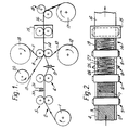
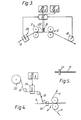
- a composite metal/plastic foil or a laminate 2 consisting of a raw material metal foil 3 laminated to a somewhat wider insulation film 4 as illustrated in Fig. 2, in which the apparatus of Fig. 1 is schematically illustrated and some of the machine parts have been removed for clarification.
- the lamination process may alternatively be undertaken in a conventional tandem process (not shown) prior to feeding of the laminate to a set of feeding rollers 5 or other foil moving means.
- the composite foil is now pulled towards a second set of foil moving means 6 while a set of cutting knives 30, 31 are arranged to cut the foil as illustrated in Fig. 2.
- a set of cutting knives 30, 31 are arranged to cut the foil as illustrated in Fig. 2.
- some other examples of cutting devices may be foreseen. Two examples will be described in connection with Fig. 15 and 16.
- the cutting devices should preferably, as described in connection with Figures 1-3, be constituted by two knives cutting alternatively from one side and from the other side. In that way each of the knives has a fixed range along which it will cut, in order to leave a defined uncut region at alternative sides of the foil.
- Other ways of arranging such cutting devices may be to use up-and-down moving knives having edges corresponding to the desired cut length. Hinged knives working like a pair of scissors may also be designed for this purpose.
- non-mechanical cutting devices like heated wires or lasers.
- the insulation film 4 of the composite foil 2 should be of an easily stretchable material like polyethylene or nylon.
- the insulation part 4 of the composite foil is wider than the metal part 3, and the purpose of the next step in accordance with the present invention is to expand the cuts made in the composite foil by a longitudinal stretching process.
- the composite foil 2 is therefore passed over a third foil moving device 8 which rotates or moves at a longitudinal speed slightly higher than that of the foil moving means 5 and 6.
- a foil tension monitoring device 9 In order to control the stretching process, there is arranged a foil tension monitoring device 9.
- the cut and stretched composite foil 2 is laminated to an insulation film 11 and possibly also to a film 10 supplied respectively from supply reels 13 and 12.
- the resulting laminate 14 is passed through an insulation foil welding device 15, to produce a laminated resistance foil 16 which may be wound onto a reel 17.
- the foil produced may be continuously measured by a foil length monitoring device 18 capable of controlling functions to be described later.
- the stretching process and/or lamination process obtained by the foil moving arrangement 8 may be combined with a bus bar application process, by which one or two longitudinal bus bars 19, which are supplied from a supply reel 20, are bonded to the side areas of the stretchable film 4.
- the bus bars 19 should preferably be applied to the same side of the stretchable film 4 as the resistance foil 3 in order to facilitate termination of the final product.
- Fig. 2 the foil tension monitoring device 9 is shown only partly in order to better illustrate the stretched foil.
- the degree of stretching is not shown to scale, as it is only necessary to move the metal strips slightly apart to provide a meander formed electrical resistance strip or path.
- the stretchable film 4 will be stretched at places indicated at 25, whereas the metal foil 3, which is made of a resistance material like lead or a lead/tin alloy or other suitable resistance material, will be stretched only negligibly in the uncut region 26, and the strip material 27 will not tend to buckle.
- the width of the resistance strips and to a certain extent also the degree of stretching can be varied in order to produce unit length mats having different resistance and wattage.
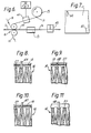
- Fig. 3 is schematically illustrated arrangements in which the cutting knives 30 and 31 are controlled by a control device 32 giving control signals to cut at desired places in order to produce heating mats with desired resistance strip widths.
- the resistance foil thickness should be as uniform as possible, and when the thickness is known within certain tolerances there may be produced unit length heating mats with a predetermined wattage simply by adjusting the width of the resistance strip.
- the control device 32 may be provided with means for setting the desired resistance or wattage values.
- the knife 30 will start cutting at a desired place and moment, and it may be arranged to follow the longitudinal movement of the foil while cutting. As soon as the knife 30 has completed its cut, it will be lifted, and the knife will return to its start point in the transverse direction of the foil as well as in the longitudinal direction of the foil. The knife 31 will now wait for its cutting signal, upon receipt of which it will complete its cut in a similar way as that described for knife 30.
- the longitudinal movement of the knives is not illustrated. In the case of full length up-and-down moving cutting knives (not shown) the cutting action may probably be undertaken so rapidly that there is no need for longitudinal knife movement.
- the thickness of the resistance foil is in the order of 5 pm-25 ⁇ m it is very difficult to obtain a uniform thickness, say 11 jM m ⁇ 5% over a complete length or roll of foil.
- This difficulty may, however, be overcome by introducing a foil thickness detection device 33.
- signals from the device 33 are fed to the control device 32, in which the cutting order settings are modified so that the cutting knives 30 and 31 produce resistance strips having, not equal and predetermined width, but equal and predetermined resistance per unit length. Thereby it is ensured that unit length heating mats having predetermined wattage may easily be produced.
- the setting of the cutting knives 30 and 31 may be facilitated by using a foil length monitoring device 18 (Fig. 3, Fig. 1) which for instance may be arranged to send electrical synchronization signals to the control device 32.
- the device 18 may for instance be arranged to generate and transmit one signal pulse per cm of foil length.
- An alternative position of the foil length monitoring device 18 may be immediately after the welding device 15, Fig. 1 where the laminated resistance foil 16 is fully stabilized.
- control device 32 On basis of a desired mat length the control device 32 is set to cut a desired number of cuts in the composite foil 2 so that termination means can be provided at desired places. Termination can be made by means of tinned copper strips or tapes which are soldered or welded to the resistance strips and bus bars.
- the mat termination can be realized in two ways.
- One way of realizing termination is illustrated in Fig. 4 showing means for providing the bus bars 19 with connecting terminals 35.
- the bus bars 19 from the supply reel 20 pass a soldering apparatus 36 in which the connecting terminals 35 are soldered, as is also illustrated in Fig. 5, to the bus bars 19 at predetermined places.
- the electrical interconection between connecting terminals 35 and the resistance strip 27 (Fig. 2) may be undertaken in a soldering machine 37 before laminating the composite foil 2 between the insulation films 10 and 11. It will, however, also be possible to complete this soldered interconnection at a later stage, e.g. after the welding machine 15, because the very little heat which is required to obtain a good connection will hardly damage the films 10 and 11. Possible damages of the films 10 and 11 at the soldering place can be easily sealed.
- Connecting terminals 48 Fig. 11 would, if required, have to be provided in the soldering machine 37.
- FIG. 6 Another way of realizing termination is by providing apertures or holes 40, Fig. 7 at predetermined places in the insulation film 11 before it is welded to the cut composite foil 2, so as to leave access to the bus bars 19 and desired portions of the resistance strip 27 and facilitate mounting of the connecting terminals.
- Fig. 6 where the insulation film 11 supplied from the reel 13 passes a hole punching machine 41 before it is laminated to the foil 2, bar bar(s) 19 and insulation film 10.
- the bus bar(s) 19 may or may not be provided with connecting terminals 35.
- the connecting terminals 35 or termination strips 45-47 (Figs. 8-10) may be provided in a termination soldering machine 42 placed after the welding machine 15 or at some later stage.
- the connecting terminals 48, Fig. 11 may be provided in the soldering machine 42 or at some later stage.
- the soldering machine 42 may be controlled from the control device 32, Fig. 3.
- the punching machine 41 and the soldering machine 36, Fig. 4 may be controlled from the control device 32, Fig. 3.
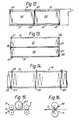
- FIG. 8-10 are respectively illustrated termination means 45-47 by which the resistance foil 16 is provided with external connection 45 to bus bar 19 and resistance strip 27, Fig. 8, internal connection 46 between bus bar 19 and resistance strip 27, Fig. 9, and external connection with the bus bar 19 only, Fig. 10. All these connections may be provided with the programmed soldering machine 36, Fig. 4.
- Fig. 11 is illustrated an external connection 48 with the resistance strip 27.
- Such connection to a foil side area not provided with a bus bar, may be obtained through apertures 40, Fig. 7, by soldering the connecting terminal 48 to the strip 27.
- Fig. 14 is schematically illustrated how the continuous resistance foil 16 may be provided with connecting terminal 45.
- this foil For making heating mats out of the laminated resistance foil 16, this foil must be cut transversly into mats of suitable length. While the distance between successive connecting terminals 45 connected to the upper bus bar 19 substantially corresponds to the desired mat length, so does the distance between sucessive connecting terminals connected to the lower bus bar.
- the foil When cutting the continuous resistance foil 16 into individual mats 50, Fig. 12 the foil should be cut as indicated by cutting lines 60, Fig. 14. The number of zig-zags between any two cutting lines will usually be so high that there is no difficulty in obtaining unit length mats having substantially the same resistance.
- Fig. 12 there are shown two heating mats 50 each provided with two connecting terminals 45.
- the bus bars 19 have only a foil stabilizing function and in principle the mats could be without bus bars if they were provided with connecting terminals 48, Fig. 11.
- Several mats may then easily be connected in parallel as illustrated, and the connecting terminals 45 can be connected to mains or to other suitable power supply.
- Fig. 13 is schematically illustrated alternative heating mats 55 which may be connected in series. As shown, each mat 55 is provided with one bus bar 19 only, and there are three types of connections, - 46 providing international connection between the bus bar 19 and the resistance strip 27, - 47 providing external connection from the bus bar 19, - and 48 providing external connection from the resistance foil 27.
- the connections 48 may preferably be provided in a process subsequent to provision of predetermined apertures 40, Fig. 7 in the insulation film 10 before it is welded to the composite foil 2.
- Suitable floor, wall and ceiling heating mats can have sizes in the range of 0,5-10 m 2 , the resistance strip width being in the range of 2-20 mm, giving powers in the range of 50-500 Watts per m 2 .
- a roller 65, Fig. 15, provided with equally distributed longitudinal cutting knives, the knives of the cutting roller moving at a speed corresponding to the longitudinal speed of the composite foil moving from the moving means 5 to the moving means 6.
- the rollers 5, 6 and the cutting roller 65 could be geared to the same peripheral speed.
Landscapes
- Engineering & Computer Science (AREA)
- Composite Materials (AREA)
- Mechanical Engineering (AREA)
- Chemical & Material Sciences (AREA)
- Resistance Heating (AREA)
- Electronic Switches (AREA)
- Floor Finish (AREA)
- Lining Or Joining Of Plastics Or The Like (AREA)
- Laminated Bodies (AREA)
- Central Heating Systems (AREA)
- Constitution Of High-Frequency Heating (AREA)
- Lighting Device Outwards From Vehicle And Optical Signal (AREA)
- Medicines Containing Material From Animals Or Micro-Organisms (AREA)
- Surface Heating Bodies (AREA)
- Steam Or Hot-Water Central Heating Systems (AREA)
- Mounting, Exchange, And Manufacturing Of Dies (AREA)
- Heating, Cooling, Or Curing Plastics Or The Like In General (AREA)
Claims (5)
Priority Applications (1)
| Application Number | Priority Date | Filing Date | Title |
|---|---|---|---|
| AT81102034T ATE8192T1 (de) | 1980-03-25 | 1981-03-19 | Verfahren zur herstellung elektrisch beheizter matten. |
Applications Claiming Priority (2)
| Application Number | Priority Date | Filing Date | Title |
|---|---|---|---|
| NO800849A NO146042C (no) | 1980-03-25 | 1980-03-25 | Fremgangsmaate for fremstilling av elektriske varmeelementer |
| NO800849 | 1980-03-25 |
Publications (2)
| Publication Number | Publication Date |
|---|---|
| EP0036633A1 EP0036633A1 (de) | 1981-09-30 |
| EP0036633B1 true EP0036633B1 (de) | 1984-06-27 |
Family
ID=19885403
Family Applications (1)
| Application Number | Title | Priority Date | Filing Date |
|---|---|---|---|
| EP81102034A Expired EP0036633B1 (de) | 1980-03-25 | 1981-03-19 | Verfahren zur Herstellung elektrisch beheizter Matten |
Country Status (9)
| Country | Link |
|---|---|
| US (1) | US4354886A (de) |
| EP (1) | EP0036633B1 (de) |
| AT (1) | ATE8192T1 (de) |
| CA (1) | CA1184749A (de) |
| DE (1) | DE3164384D1 (de) |
| DK (1) | DK131981A (de) |
| ES (1) | ES8203005A1 (de) |
| FI (1) | FI67987C (de) |
| NO (1) | NO146042C (de) |
Families Citing this family (10)
| Publication number | Priority date | Publication date | Assignee | Title |
|---|---|---|---|---|
| NL8400410A (nl) * | 1984-02-09 | 1985-09-02 | Inventum Koninklijke Fab | Werkwijze en inrichting voor het in een bepaald patroon tussen respectievelijk materiaallagen en materiaalbanen aanbrengen van een draadvormig element, in het bijzonder voor toepassing bij de vervaardiging van electrisch verwarmde voorwerpen, zoals dekens en kussens, waarbij het draadvormig element een verwarmingskabel is. |
| NO157840C (no) * | 1984-09-10 | 1988-05-25 | Standard Tel Kabelfab As | Elektrisk varmeelement. |
| US4888472A (en) * | 1988-05-12 | 1989-12-19 | David G. Stitz | Radiant heating panels |
| SE9203007D0 (sv) * | 1992-10-13 | 1992-10-13 | Tetra Alfa Holdings | Saett att framstaella foerpackningsmaterial i form av en sammanhaengande laminatbana |
| CA2435164A1 (en) * | 2002-07-15 | 2004-01-15 | Magna Donnelly Mirrors North America L.L.C. | Resizeable mirror heating element and vehicular mirror assembly incorporating the same |
| ATE510946T1 (de) * | 2005-04-18 | 2011-06-15 | Teijin Ltd | Teerbasierte kohlenstofffaservlies |
| JP2011521187A (ja) * | 2009-04-06 | 2011-07-21 | ジョンゴン ソン | 熱反射断熱材の製造装置およびその製造方法 |
| CN105523418B (zh) * | 2016-01-05 | 2017-05-31 | 长园电子(东莞)有限公司 | 一种热缩扁管在线上盘设备 |
| US12048608B2 (en) | 2021-11-09 | 2024-07-30 | Vivos Therapeutics, Inc. | Vibrational oral appliance with mandibular advancements |
| US11723790B2 (en) | 2021-11-09 | 2023-08-15 | Vivos Therapeutics, Inc. | Vibrational oral appliance with mandibular advancements |
Citations (2)
| Publication number | Priority date | Publication date | Assignee | Title |
|---|---|---|---|---|
| BE634716A (de) * | 1963-07-09 | 1963-11-18 | ||
| US3721800A (en) * | 1961-01-20 | 1973-03-20 | P Eisler | Electrical heating film |
Family Cites Families (14)
| Publication number | Priority date | Publication date | Assignee | Title |
|---|---|---|---|---|
| AT36866B (de) * | 1907-03-03 | 1909-04-10 | Norris Elmore Clark | Verfahren und Maschine zur Herstellung von Blechgittern. |
| US1802811A (en) * | 1926-04-30 | 1931-04-28 | Harvey M Gersman | Method of expanding metal |
| US2320092A (en) * | 1940-10-23 | 1943-05-25 | Scholl Mfg Co Inc | Machine for making adhesive pads |
| US3149406A (en) * | 1958-11-10 | 1964-09-22 | Eisler Paul | Method of making electrical heating and conducting devices |
| US3255065A (en) * | 1961-06-02 | 1966-06-07 | Fmc Corp | Method for making a composite film |
| US3427712A (en) * | 1963-07-09 | 1969-02-18 | Albert Norbert Robert Witdoeck | Method of making an electrical resistor |
| GB1192927A (en) * | 1966-10-03 | 1970-05-28 | Peter Davie | Improvements relating to Apparatus for the Production of Electric Heating Elements |
| US3431613A (en) * | 1967-04-17 | 1969-03-11 | Acker Ind Inc | Sheet material forming machine |
| BE754974A (fr) * | 1969-06-27 | 1971-02-18 | Cellu Prod Co | Procede de fabrication de materiaux thermoplastiques reticulaires ou analogues, produits pour son execution et articles ainsi obtenus, |
| US3668956A (en) * | 1970-08-04 | 1972-06-13 | Nasa | Microcircuit negative cutter |
| GB1308708A (en) * | 1970-12-09 | 1973-03-07 | Langley London Ltd | Resistors and heating elements |
| US4025893A (en) * | 1972-10-13 | 1977-05-24 | Patentkonsortiet Robert Meinich & Co. | Continuous web consisting of resistance foil material between two insulating foil layers and method for the production of such webs |
| SE396195B (sv) * | 1976-02-05 | 1977-09-12 | Aga Ab | Anordning for perforering av ett band |
| US4139763A (en) * | 1978-03-10 | 1979-02-13 | Mcmullan James P | Blanket heater with temperature control means |
-
1980
- 1980-03-25 NO NO800849A patent/NO146042C/no unknown
-
1981
- 1981-03-10 US US06/242,492 patent/US4354886A/en not_active Expired - Fee Related
- 1981-03-17 CA CA000373236A patent/CA1184749A/en not_active Expired
- 1981-03-19 EP EP81102034A patent/EP0036633B1/de not_active Expired
- 1981-03-19 DE DE8181102034T patent/DE3164384D1/de not_active Expired
- 1981-03-19 AT AT81102034T patent/ATE8192T1/de not_active IP Right Cessation
- 1981-03-23 FI FI810888A patent/FI67987C/fi not_active IP Right Cessation
- 1981-03-24 ES ES500652A patent/ES8203005A1/es not_active Expired
- 1981-03-24 DK DK131981A patent/DK131981A/da not_active Application Discontinuation
Patent Citations (2)
| Publication number | Priority date | Publication date | Assignee | Title |
|---|---|---|---|---|
| US3721800A (en) * | 1961-01-20 | 1973-03-20 | P Eisler | Electrical heating film |
| BE634716A (de) * | 1963-07-09 | 1963-11-18 |
Also Published As
| Publication number | Publication date |
|---|---|
| CA1184749A (en) | 1985-04-02 |
| DE3164384D1 (en) | 1984-08-02 |
| NO800849L (no) | 1981-09-28 |
| ES500652A0 (es) | 1982-03-01 |
| FI67987C (fi) | 1985-06-10 |
| US4354886A (en) | 1982-10-19 |
| ES8203005A1 (es) | 1982-03-01 |
| EP0036633A1 (de) | 1981-09-30 |
| ATE8192T1 (de) | 1984-07-15 |
| FI67987B (fi) | 1985-02-28 |
| FI810888L (fi) | 1981-09-26 |
| DK131981A (da) | 1981-09-26 |
| NO146042C (no) | 1982-07-14 |
| NO146042B (no) | 1982-04-05 |
Similar Documents
| Publication | Publication Date | Title |
|---|---|---|
| EP0036633B1 (de) | Verfahren zur Herstellung elektrisch beheizter Matten | |
| US3913219A (en) | Planar circuit fabrication process | |
| US3884742A (en) | Method of making plastic book cover | |
| EP0059723B1 (de) | Konstruktionen von modifizierten indexierungsschwingkreisen und verfahren zu ihrer herstellung | |
| DE69311202T2 (de) | Vorrichtung und Verfahren bei der Herstellung flexiblen Flachkabels durch Verbinden von Blattmaterial | |
| US4045272A (en) | Apparatus for sealing plastic films and the like | |
| JPS63237195A (ja) | 共振ラベルとその製造方法 | |
| GB2031796A (en) | Erforations to sheet metal apparatus for sticking nonconductive tape having plating p | |
| US3240647A (en) | Laminated printed circuit and method of making | |
| US4259134A (en) | Polymer film slitter-sealer apparatus and method | |
| US4707207A (en) | Method for processing and applying a protective foil | |
| US4092626A (en) | Continuous web consisting of resistance foil material between two insulating foil layers and method for the production of such webs | |
| EP1472089B1 (de) | Maschine zur kontinuierlichen herstellung von kunststoff-laminaten in einer kaltpresse | |
| US3810304A (en) | Method of producing thin, flexible heating elements | |
| US3336557A (en) | Electrical heating mats and blanks therefor | |
| US6308406B1 (en) | Method for forming an electrical conductive circuit on a substrate | |
| US4025893A (en) | Continuous web consisting of resistance foil material between two insulating foil layers and method for the production of such webs | |
| GB1523478A (en) | Convoluted resistive-capacitive devices an methods of forming them | |
| CN107809859B (zh) | 一种用于led灯带的多层电路板生产设备 | |
| CN107809848B (zh) | 一种用于led灯带的电路板生产设备 | |
| CN223890099U (zh) | 一种高光pet胶片的加工设备 | |
| JP2688160B2 (ja) | 熱可塑性不織布の製造方法及び装置並びに熱可塑性不織布 | |
| JP2834472B2 (ja) | 長尺テープ電線製造装置 | |
| CN221662198U (zh) | 一种分切膜料带的绕卷装置 | |
| CN220392860U (zh) | 一种塑料膜分切机 |
Legal Events
| Date | Code | Title | Description |
|---|---|---|---|
| PUAI | Public reference made under article 153(3) epc to a published international application that has entered the european phase |
Free format text: ORIGINAL CODE: 0009012 |
|
| AK | Designated contracting states |
Designated state(s): AT BE CH DE FR GB IT LI NL SE |
|
| 17P | Request for examination filed |
Effective date: 19811215 |
|
| ITF | It: translation for a ep patent filed | ||
| GRAA | (expected) grant |
Free format text: ORIGINAL CODE: 0009210 |
|
| AK | Designated contracting states |
Designated state(s): AT BE CH DE FR GB IT LI NL SE |
|
| REF | Corresponds to: |
Ref document number: 8192 Country of ref document: AT Date of ref document: 19840715 Kind code of ref document: T |
|
| REF | Corresponds to: |
Ref document number: 3164384 Country of ref document: DE Date of ref document: 19840802 |
|
| ET | Fr: translation filed | ||
| BECA | Be: change of holder's address |
Free format text: 840627 *ALCATEL N.V.STRAWINSKYLAAN 537, NL-1077 XX AMSTERDAM |
|
| BECH | Be: change of holder |
Free format text: 840627 *ALCATEL N.V. |
|
| PLBE | No opposition filed within time limit |
Free format text: ORIGINAL CODE: 0009261 |
|
| STAA | Information on the status of an ep patent application or granted ep patent |
Free format text: STATUS: NO OPPOSITION FILED WITHIN TIME LIMIT |
|
| 26N | No opposition filed | ||
| PGFP | Annual fee paid to national office [announced via postgrant information from national office to epo] |
Ref country code: AT Payment date: 19870312 Year of fee payment: 7 |
|
| PGFP | Annual fee paid to national office [announced via postgrant information from national office to epo] |
Ref country code: NL Payment date: 19870331 Year of fee payment: 7 |
|
| REG | Reference to a national code |
Ref country code: CH Ref legal event code: PUE Owner name: ALCATEL N.V. |
|
| REG | Reference to a national code |
Ref country code: FR Ref legal event code: TP |
|
| REG | Reference to a national code |
Ref country code: GB Ref legal event code: 732 |
|
| NLS | Nl: assignments of ep-patents |
Owner name: ALCATEL N.V. TE AMSTERDAM. |
|
| PG25 | Lapsed in a contracting state [announced via postgrant information from national office to epo] |
Ref country code: AT Effective date: 19880319 |
|
| PG25 | Lapsed in a contracting state [announced via postgrant information from national office to epo] |
Ref country code: SE Effective date: 19880320 |
|
| PG25 | Lapsed in a contracting state [announced via postgrant information from national office to epo] |
Ref country code: LI Effective date: 19880331 Ref country code: CH Effective date: 19880331 |
|
| BERE | Be: lapsed |
Owner name: ALCATEL N.V. Effective date: 19880331 |
|
| PG25 | Lapsed in a contracting state [announced via postgrant information from national office to epo] |
Ref country code: NL Effective date: 19881001 |
|
| NLV4 | Nl: lapsed or anulled due to non-payment of the annual fee | ||
| PG25 | Lapsed in a contracting state [announced via postgrant information from national office to epo] |
Ref country code: GB Free format text: LAPSE BECAUSE OF NON-PAYMENT OF DUE FEES Effective date: 19881118 |
|
| GBPC | Gb: european patent ceased through non-payment of renewal fee | ||
| REG | Reference to a national code |
Ref country code: CH Ref legal event code: PL |
|
| PG25 | Lapsed in a contracting state [announced via postgrant information from national office to epo] |
Ref country code: DE Effective date: 19881201 |
|
| PG25 | Lapsed in a contracting state [announced via postgrant information from national office to epo] |
Ref country code: BE Effective date: 19890331 |
|
| PG25 | Lapsed in a contracting state [announced via postgrant information from national office to epo] |
Ref country code: FR Free format text: LAPSE BECAUSE OF NON-PAYMENT OF DUE FEES Effective date: 19891130 |
|
| REG | Reference to a national code |
Ref country code: FR Ref legal event code: ST |
|
| EUG | Se: european patent has lapsed |
Ref document number: 81102034.6 Effective date: 19881205 |