EP0035930B1 - Support d'antenne de réception d'émissions d'un satellite géostationnaire, et antenne comportant un tel support - Google Patents
Support d'antenne de réception d'émissions d'un satellite géostationnaire, et antenne comportant un tel support Download PDFInfo
- Publication number
- EP0035930B1 EP0035930B1 EP81400313A EP81400313A EP0035930B1 EP 0035930 B1 EP0035930 B1 EP 0035930B1 EP 81400313 A EP81400313 A EP 81400313A EP 81400313 A EP81400313 A EP 81400313A EP 0035930 B1 EP0035930 B1 EP 0035930B1
- Authority
- EP
- European Patent Office
- Prior art keywords
- antenna
- post
- mounting according
- mounting
- articulated
- Prior art date
- Legal status (The legal status is an assumption and is not a legal conclusion. Google has not performed a legal analysis and makes no representation as to the accuracy of the status listed.)
- Expired
Links
- 230000005540 biological transmission Effects 0.000 claims description 3
- 238000009434 installation Methods 0.000 description 5
- 210000005069 ears Anatomy 0.000 description 4
- 239000002184 metal Substances 0.000 description 2
- 238000013459 approach Methods 0.000 description 1
- 230000000903 blocking effect Effects 0.000 description 1
- 230000003100 immobilizing effect Effects 0.000 description 1
- 230000001360 synchronised effect Effects 0.000 description 1
Images
Classifications
-
- H—ELECTRICITY
- H01—ELECTRIC ELEMENTS
- H01Q—ANTENNAS, i.e. RADIO AERIALS
- H01Q1/00—Details of, or arrangements associated with, antennas
- H01Q1/12—Supports; Mounting means
- H01Q1/125—Means for positioning
Definitions
- the present invention relates to an antenna support for the direct reception of television broadcasts from a geostationary satellite.
- the invention also relates to an antenna carried by such a support.
- each television receiver can then be associated with a small antenna pointed at the transmitting geostationary satellite.
- the antenna can be turned once and for all in the direction of this transmitting satellite. However, it is necessary to be able to adjust this antenna, in azimuth and in elevation, at the time of its installation, in a precise but simple manner so that this adjustment can be carried out by an inexperienced person.
- the antenna support according to the invention is simple and economical and allows the user to easily adjust the azimuth and the site of this antenna during its installation.
- the geostationary satellite telecommunication antenna support according to the invention is characterized in that it comprises: a steering pole fixed relative to the ground and able to rotate around its longitudinal axis to adjust the azimuth of the antenna, and an articulated quadrilateral of which one side constitutes a part of the antenna and another side is a part of the pole, the length of this part being adjustable and determining the site of the antenna.
- the post is vertical.
- the post can be fixed to a wall by means of flanges. It can also be fixed to another post driven into the ground also by means of flanges.
- the lower end of the pole is introduced into a hole with a vertical axis of a base, this pole being able to rotate about its axis in its housing in the base, means being however provided for immobilizing said pole.
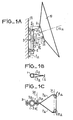
- a paraboloidal antenna 10 is symbolized in FIG. 1A. This antenna is mounted on its support and the axis of its paraboloid reflector is pointed towards the transmitting satellite.
- the support comprises a tube 1, the ends of which are clamped in collars 2. These collars comprise two parts in the form of an arc of a circle which are held around the tube 1 by tightening bolts.
- One of the two parts of the collars 2 is integral with a foot 4 by means of which the collars 2, and therefore the tube 1 are fixed to a vertical wall 11.
- the two half-flanges 3a have been shown in cross section, positioned around the tube using the two bolts 9.
- the arm 7 of invariable length comprises two identical metal blades 7a. These two blades are at one of their ends, clamped one against the other between the two half-flanges by means of one of the tightening bolts 9a.
- the two blades 7a are preformed so as to constitute an isosceles triangle, the apex of which is on the tightening bolt 9a and the base, the active line connecting the two ears 8a fixed to the rear of the antenna 10.
- the ears 8a are integral with the antenna 10 at a predetermined distance from the upper ear 6, so as to preferably form an isosceles triangle whose apex is the upper ear 6 and the base, said fictitious straight line connecting the two ears 8a.
- the ends of the metal blades are held on the lugs 8a by tightening bolts.
- the arm 7 is articulated on the one hand to the flange 3 along a horizontal axis and on the other hand to the ears 8a of the antenna 10, along a horizontal axis 31.
- Part 1b of the post 1 between the flange 3 and the arm 5 forms one side of a quadrilateral with three articulations 30, 31 and 6a whose three other sides are the arms 5 and 7 and the fictitious line connecting the ear 6 at a point on the axis 31. It is by varying the length of the part 1b that the axis 10a is pivoted.
- the direction of the axis of symmetry 10a of the dish of the antenna 10 therefore depends on the position of the flange 3 on the tube 1.
- the adjustment of the direction of axis 10a in a vertical plane that is to say of its site.
- the tube 1 being able to pivot about its axis of symmetry, and the antenna 10 being integral with the tube 1 via the arms 5 and 7, this antenna 10 can pivot around the axis 1a. This pivoting of the tube 1 therefore makes it possible to orient the azimuth of the antenna 10.
- the antenna 10 support is therefore initially fixed, by means of the feet 4 of the collars 2, on the wall 11, for example so that the tube 1 either in a meridian plane.
- the installer can then act on the flange 3 so that the axis 10a forms with the vertical of the place where the antenna is mounted, an angle equal to the latitude of the location of the antenna.
- the position of the axis of the paraboloid being linked to the position of the flange 3, it is possible to identify the position of this axis by graduating the tube 1 with marks 15, each mark corresponding to a precise position of the flange 3 and therefore from the site of the paraboloid axis.
- a concordance table gives the reference 15 corresponding to the known latitude of the place where the antenna 10 should be placed.
- the axis 10a of the paraboloid is in a plane substantially parallel to the plane of the equator .
- the geostationary satellites being in the plane of the equator and at an altitude substantially equal to 36,000 km, it is possible to select the satellite to be received by rotating the antenna 10 around the vertical axis ie say the tube 1 inside the collars 2.
- the collars 2 can be graduated so that a mark of this graduation corresponds to a transmitting geostationary satellite.
- This adjustment can be refined by connecting the antenna 10 to a control receiver and by slightly modifying the initial settings so as to obtain the best possible image.
- the antenna is immobilized by tightening all the bolts of the collars 2 and the flange 3.
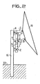
- FIG. 2 represents a second embodiment of the support according to the invention.
- the support of Figure 1A is fixed via the feet 4 of the collars 2 on another post 16 which, in a preferred embodiment is of square section.
- This post 16 is planted in a horizontal concrete slab 33. This embodiment allows for example the fixing of the antenna in a garden.
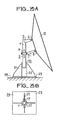
- FIG. 3A represents a third embodiment of the invention.
- the tube 1 provided with its arm 5 and its flange 3 no longer has a fixing collar, but at its lower end inserted in a base comprising a foot 20.
- This foot 20 has a hollow cylindrical part 22 in which the tube 1 is positioned, this cylindrical part is held in a vertical position on a horizontal plate 23 by four support pieces 21. This foot is shown in top view in FIG. 3B.
- the edge of the cylindrical part 22 is graduated by marks 17 equivalent to those arranged on the collars 2 of FIGS. 1A and 2, the tube 1 being able to pivot around its axis of symmetry inside this cylindrical part so as to adjust the azimuth of the antenna 10.
- Tube 1 blocking means such as a stop screw, are associated with this cylindrical part 22.
- the plate 23 is fixed to a horizontal slab 30.
- These antenna supports therefore allow easy adjustment of the antenna 10 and are more particularly suitable, although not exclusively, for the installation of antennas intended to be oriented definitively towards the same satellite.
- antenna support are more particularly suited to antennas for direct reception of satellite television transmissions.
Landscapes
- Support Of Aerials (AREA)
- Variable-Direction Aerials And Aerial Arrays (AREA)
Applications Claiming Priority (2)
| Application Number | Priority Date | Filing Date | Title |
|---|---|---|---|
| FR8005415A FR2478378A1 (fr) | 1980-03-11 | 1980-03-11 | Support d'antenne de telecommunication par satellite geostationnaire et antenne comportant un tel support |
| FR8005415 | 1980-03-11 |
Publications (2)
| Publication Number | Publication Date |
|---|---|
| EP0035930A1 EP0035930A1 (fr) | 1981-09-16 |
| EP0035930B1 true EP0035930B1 (fr) | 1984-06-20 |
Family
ID=9239536
Family Applications (1)
| Application Number | Title | Priority Date | Filing Date |
|---|---|---|---|
| EP81400313A Expired EP0035930B1 (fr) | 1980-03-11 | 1981-02-27 | Support d'antenne de réception d'émissions d'un satellite géostationnaire, et antenne comportant un tel support |
Country Status (5)
| Country | Link |
|---|---|
| EP (1) | EP0035930B1 (enExample) |
| AU (1) | AU541769B2 (enExample) |
| DE (1) | DE3164260D1 (enExample) |
| FR (1) | FR2478378A1 (enExample) |
| IN (1) | IN155634B (enExample) |
Cited By (1)
| Publication number | Priority date | Publication date | Assignee | Title |
|---|---|---|---|---|
| RU2352033C1 (ru) * | 2007-07-20 | 2009-04-10 | Открытое акционерное общество "Концерн радиостроения "Вега" | Гибридная зеркальная антенна с расширенными углами секторного сканирования |
Families Citing this family (10)
| Publication number | Priority date | Publication date | Assignee | Title |
|---|---|---|---|---|
| FR2514570A1 (fr) * | 1981-10-09 | 1983-04-15 | Thomson Brandt | Support d'antenne destinee a capter des emissions de television provenant d'un satellite geostationnaire et ensemble forme par un tel support et son antenne |
| FR2536591B1 (fr) * | 1982-11-23 | 1985-09-20 | Thomson Brandt | Support d'antenne de telecommunications par satellite geostationnaire et ensemble forme par un tel support et son antenne |
| FR2539920A1 (fr) * | 1983-01-20 | 1984-07-27 | Thomson Brandt | Support d'antenne de reception d'emissions hertziennes par satellite geostationnaire |
| DE3715024A1 (de) * | 1987-05-06 | 1988-11-17 | Kathrein Werke Kg | Einstellvorrichtung fuer eine antenne |
| GB2209095A (en) * | 1987-08-25 | 1989-04-26 | Varitrack D B S Limited | Method of mounting a dished telecommunications receiver |
| EP0291268A3 (en) * | 1987-05-11 | 1989-10-18 | Varitrack Dbs Limited | Mountings for telecommunications dishes |
| EP0940879A1 (en) * | 1998-03-04 | 1999-09-08 | Lucent Technologies Inc. | Bracket |
| RU2392707C1 (ru) * | 2009-01-28 | 2010-06-20 | Открытое акционерное общество "Концерн радиостроения "Вега" | Гибридная зеркальная сканирующая антенна для многорежимного космического радиолокатора с синтезированной апертурой |
| CN102931469B (zh) * | 2012-11-20 | 2015-05-13 | 广州赛宝计量检测中心服务有限公司 | 一种标准增益喇叭天线定位装置 |
| CN107749773B (zh) * | 2017-09-25 | 2022-09-02 | 全球能源互联网研究院 | 一种卫星通信系统及其通信方法 |
Family Cites Families (5)
| Publication number | Priority date | Publication date | Assignee | Title |
|---|---|---|---|---|
| GB933616A (en) * | 1961-04-10 | 1963-08-08 | Henry Charles Husband | Improvements in and relating to tiltable frame-like structures |
| GB1234231A (enExample) * | 1968-01-26 | 1971-06-03 | ||
| FR2252663B1 (enExample) * | 1973-11-22 | 1978-12-01 | Gueguen Michel | |
| JPS6013321B2 (ja) * | 1975-11-11 | 1985-04-06 | イギリス国 | 衛星追跡装置 |
| DE2643539A1 (de) * | 1976-09-28 | 1978-03-30 | Johann Prof Dr I Kleinwaechter | Solarkonzentratoren mit pneumatischer spiegeloptik |
-
1980
- 1980-03-11 FR FR8005415A patent/FR2478378A1/fr active Granted
-
1981
- 1981-02-27 DE DE8181400313T patent/DE3164260D1/de not_active Expired
- 1981-02-27 EP EP81400313A patent/EP0035930B1/fr not_active Expired
- 1981-03-04 IN IN121/DEL/81A patent/IN155634B/en unknown
- 1981-03-10 AU AU68211/81A patent/AU541769B2/en not_active Expired - Fee Related
Non-Patent Citations (1)
| Title |
|---|
| MacGraw Hill Encyclopedia of Science and Technology p. 665 * |
Cited By (1)
| Publication number | Priority date | Publication date | Assignee | Title |
|---|---|---|---|---|
| RU2352033C1 (ru) * | 2007-07-20 | 2009-04-10 | Открытое акционерное общество "Концерн радиостроения "Вега" | Гибридная зеркальная антенна с расширенными углами секторного сканирования |
Also Published As
| Publication number | Publication date |
|---|---|
| FR2478378A1 (fr) | 1981-09-18 |
| EP0035930A1 (fr) | 1981-09-16 |
| DE3164260D1 (en) | 1984-07-26 |
| AU541769B2 (en) | 1985-01-17 |
| IN155634B (enExample) | 1985-02-16 |
| AU6821181A (en) | 1981-09-17 |
| FR2478378B1 (enExample) | 1984-08-03 |
Similar Documents
| Publication | Publication Date | Title |
|---|---|---|
| EP0035930B1 (fr) | Support d'antenne de réception d'émissions d'un satellite géostationnaire, et antenne comportant un tel support | |
| FR2815477A1 (fr) | Supports pour la fixation sur un mat d'une ou plusieurs antennes relais de systemes de radio-telecommunication cellulaire et dispositi pour le reglage de l'orientation d'une telle antenne | |
| WO2000039885A1 (fr) | Procede et dispositif de pointage et de positionnement d'une antenne multisatellite | |
| FR2473796A1 (fr) | Support d'antenne orientable et antenne equipee d'un tel support | |
| FR2608846A1 (fr) | Antenne de telecommunications a reflecteur | |
| FR2701337A1 (fr) | Support universel de têtes pour la réception multiple de satellites sur une seule antenne parabolique fixe. | |
| EP0114543B1 (fr) | Dispositif d'orientation omnidirectionnelle d'une antenne | |
| JPS60136401A (ja) | アンテナ架台 | |
| FR2745423A1 (fr) | Support d'antenne | |
| FR2853766A1 (fr) | Monture d'antenne permettant un reglage fin de l'orientation de l'antenne | |
| EP0112205A1 (fr) | Support d'antenne de télécommunications par satellite géostationnaire et ensemble formé par un tel support et son antenne | |
| FR2471058A3 (fr) | Support d'antenne pour reception de satellite geo-stationnaire, et antenne munie d'un tel support | |
| FR2696281A1 (fr) | Monture d'antenne à pointage réglable, notamment pour antenne de télécommunications par satellite. | |
| EP0364974A2 (fr) | Support d'antenne de type azimut-élévation | |
| JPH0669722A (ja) | マルチビームアンテナ | |
| FR2595510A1 (fr) | Support d'antenne de reception | |
| WO2004109845A1 (fr) | Monture d’antenne permettant un reglage fin de l’orientation en azimut de l’antenne | |
| EP0838876B1 (fr) | Dispositif de réception par satellite comportant une antenne plane | |
| FR2824957A1 (fr) | Procede et dispositif de reglage de l'orientation d'une antenne permettant un reglage fin | |
| EP0077250A1 (fr) | Support d'antenne destinée à capter des émissions de télévision provenant d'un satellite géostationnaire, et ensemble formé par un tel support et son antenne | |
| FR2555820A1 (fr) | Mat pouvant supporter au moins deux dispositifs orientables et elements constituant ce mat | |
| JP2577893B2 (ja) | パラボラアンテナ支持具 | |
| FR2539920A1 (fr) | Support d'antenne de reception d'emissions hertziennes par satellite geostationnaire | |
| EP2713435A1 (fr) | Système de montage d'une antenne sur un support cylindrique | |
| FR2501421A1 (fr) | Antenne pour la reception d'emissions d'un satellite geostationnaire et son procede de fabrication |
Legal Events
| Date | Code | Title | Description |
|---|---|---|---|
| PUAI | Public reference made under article 153(3) epc to a published international application that has entered the european phase |
Free format text: ORIGINAL CODE: 0009012 |
|
| AK | Designated contracting states |
Designated state(s): DE |
|
| 17P | Request for examination filed |
Effective date: 19810924 |
|
| RBV | Designated contracting states (corrected) |
Designated state(s): DE |
|
| GRAA | (expected) grant |
Free format text: ORIGINAL CODE: 0009210 |
|
| RAP1 | Party data changed (applicant data changed or rights of an application transferred) |
Owner name: SOCIETE D'ELECTRONIQUE DE LA REGION PAYS DE LOIRE |
|
| AK | Designated contracting states |
Designated state(s): DE |
|
| REF | Corresponds to: |
Ref document number: 3164260 Country of ref document: DE Date of ref document: 19840726 |
|
| PGFP | Annual fee paid to national office [announced via postgrant information from national office to epo] |
Ref country code: DE Payment date: 19850122 Year of fee payment: 5 |
|
| PLBE | No opposition filed within time limit |
Free format text: ORIGINAL CODE: 0009261 |
|
| STAA | Information on the status of an ep patent application or granted ep patent |
Free format text: STATUS: NO OPPOSITION FILED WITHIN TIME LIMIT |
|
| 26N | No opposition filed | ||
| PG25 | Lapsed in a contracting state [announced via postgrant information from national office to epo] |
Ref country code: DE Effective date: 19861101 |