EP0032003B1 - Vorrichtung zum Umwandeln von Alkoholen in Äther und Verfahren zum Betrieb bzw. zum Umbau einer Brennkraftmaschine, um in ihr den Gebrauch eines aus Alkohol und Äther bestehenden Treibstoffs zu ermöglichen - Google Patents
Vorrichtung zum Umwandeln von Alkoholen in Äther und Verfahren zum Betrieb bzw. zum Umbau einer Brennkraftmaschine, um in ihr den Gebrauch eines aus Alkohol und Äther bestehenden Treibstoffs zu ermöglichen Download PDFInfo
- Publication number
- EP0032003B1 EP0032003B1 EP80304416A EP80304416A EP0032003B1 EP 0032003 B1 EP0032003 B1 EP 0032003B1 EP 80304416 A EP80304416 A EP 80304416A EP 80304416 A EP80304416 A EP 80304416A EP 0032003 B1 EP0032003 B1 EP 0032003B1
- Authority
- EP
- European Patent Office
- Prior art keywords
- alcohol
- pipe
- heat exchanger
- cylinder
- engine
- Prior art date
- Legal status (The legal status is an assumption and is not a legal conclusion. Google has not performed a legal analysis and makes no representation as to the accuracy of the status listed.)
- Expired
Links
- LFQSCWFLJHTTHZ-UHFFFAOYSA-N Ethanol Chemical compound CCO LFQSCWFLJHTTHZ-UHFFFAOYSA-N 0.000 title claims description 39
- RTZKZFJDLAIYFH-UHFFFAOYSA-N Diethyl ether Chemical compound CCOCC RTZKZFJDLAIYFH-UHFFFAOYSA-N 0.000 title claims description 33
- 230000006835 compression Effects 0.000 title claims description 23
- 238000007906 compression Methods 0.000 title claims description 23
- 239000000446 fuel Substances 0.000 title claims description 19
- 238000000034 method Methods 0.000 title claims description 7
- 150000001298 alcohols Chemical class 0.000 title description 3
- 150000002170 ethers Chemical class 0.000 title description 3
- 239000003054 catalyst Substances 0.000 claims description 28
- 238000006243 chemical reaction Methods 0.000 claims description 27
- 230000003197 catalytic effect Effects 0.000 claims description 19
- 238000002347 injection Methods 0.000 claims description 8
- 239000007924 injection Substances 0.000 claims description 8
- 239000000314 lubricant Substances 0.000 claims description 8
- 238000011144 upstream manufacturing Methods 0.000 claims description 6
- OKKJLVBELUTLKV-UHFFFAOYSA-N Methanol Chemical group OC OKKJLVBELUTLKV-UHFFFAOYSA-N 0.000 description 127
- LCGLNKUTAGEVQW-UHFFFAOYSA-N Dimethyl ether Chemical compound COC LCGLNKUTAGEVQW-UHFFFAOYSA-N 0.000 description 32
- VYPSYNLAJGMNEJ-UHFFFAOYSA-N Silicium dioxide Chemical compound O=[Si]=O VYPSYNLAJGMNEJ-UHFFFAOYSA-N 0.000 description 5
- PNEYBMLMFCGWSK-UHFFFAOYSA-N aluminium oxide Inorganic materials [O-2].[O-2].[O-2].[Al+3].[Al+3] PNEYBMLMFCGWSK-UHFFFAOYSA-N 0.000 description 5
- 239000004359 castor oil Substances 0.000 description 5
- 235000019438 castor oil Nutrition 0.000 description 5
- ZEMPKEQAKRGZGQ-XOQCFJPHSA-N glycerol triricinoleate Natural products CCCCCC[C@@H](O)CC=CCCCCCCCC(=O)OC[C@@H](COC(=O)CCCCCCCC=CC[C@@H](O)CCCCCC)OC(=O)CCCCCCCC=CC[C@H](O)CCCCCC ZEMPKEQAKRGZGQ-XOQCFJPHSA-N 0.000 description 5
- 239000002283 diesel fuel Substances 0.000 description 3
- 239000007789 gas Substances 0.000 description 3
- 239000000203 mixture Substances 0.000 description 3
- 238000001816 cooling Methods 0.000 description 2
- 238000010438 heat treatment Methods 0.000 description 2
- 239000000377 silicon dioxide Substances 0.000 description 2
- XLYOFNOQVPJJNP-UHFFFAOYSA-N water Substances O XLYOFNOQVPJJNP-UHFFFAOYSA-N 0.000 description 2
- QAOWNCQODCNURD-UHFFFAOYSA-N Sulfuric acid Chemical compound OS(O)(=O)=O QAOWNCQODCNURD-UHFFFAOYSA-N 0.000 description 1
- 235000011126 aluminium potassium sulphate Nutrition 0.000 description 1
- 229910000323 aluminium silicate Inorganic materials 0.000 description 1
- 238000002485 combustion reaction Methods 0.000 description 1
- 239000002131 composite material Substances 0.000 description 1
- 150000001875 compounds Chemical class 0.000 description 1
- 230000018044 dehydration Effects 0.000 description 1
- 238000006297 dehydration reaction Methods 0.000 description 1
- 230000008021 deposition Effects 0.000 description 1
- 230000001066 destructive effect Effects 0.000 description 1
- -1 for example Substances 0.000 description 1
- 239000007788 liquid Substances 0.000 description 1
- 229910044991 metal oxide Inorganic materials 0.000 description 1
- 229940050271 potassium alum Drugs 0.000 description 1
- GRLPQNLYRHEGIJ-UHFFFAOYSA-J potassium aluminium sulfate Chemical compound [Al+3].[K+].[O-]S([O-])(=O)=O.[O-]S([O-])(=O)=O GRLPQNLYRHEGIJ-UHFFFAOYSA-J 0.000 description 1
- 239000000741 silica gel Substances 0.000 description 1
- 229910002027 silica gel Inorganic materials 0.000 description 1
- 239000000126 substance Substances 0.000 description 1
- 239000001117 sulphuric acid Substances 0.000 description 1
- 235000011149 sulphuric acid Nutrition 0.000 description 1
- 239000003981 vehicle Substances 0.000 description 1
Images


Classifications
-
- F—MECHANICAL ENGINEERING; LIGHTING; HEATING; WEAPONS; BLASTING
- F02—COMBUSTION ENGINES; HOT-GAS OR COMBUSTION-PRODUCT ENGINE PLANTS
- F02M—SUPPLYING COMBUSTION ENGINES IN GENERAL WITH COMBUSTIBLE MIXTURES OR CONSTITUENTS THEREOF
- F02M27/00—Apparatus for treating combustion-air, fuel, or fuel-air mixture, by catalysts, electric means, magnetism, rays, sound waves, or the like
- F02M27/02—Apparatus for treating combustion-air, fuel, or fuel-air mixture, by catalysts, electric means, magnetism, rays, sound waves, or the like by catalysts
-
- F—MECHANICAL ENGINEERING; LIGHTING; HEATING; WEAPONS; BLASTING
- F02—COMBUSTION ENGINES; HOT-GAS OR COMBUSTION-PRODUCT ENGINE PLANTS
- F02B—INTERNAL-COMBUSTION PISTON ENGINES; COMBUSTION ENGINES IN GENERAL
- F02B1/00—Engines characterised by fuel-air mixture compression
- F02B1/02—Engines characterised by fuel-air mixture compression with positive ignition
-
- F—MECHANICAL ENGINEERING; LIGHTING; HEATING; WEAPONS; BLASTING
- F02—COMBUSTION ENGINES; HOT-GAS OR COMBUSTION-PRODUCT ENGINE PLANTS
- F02B—INTERNAL-COMBUSTION PISTON ENGINES; COMBUSTION ENGINES IN GENERAL
- F02B69/00—Internal-combustion engines convertible into other combustion-engine type, not provided for in F02B11/00; Internal-combustion engines of different types characterised by constructions facilitating use of same main engine-parts in different types
- F02B69/02—Internal-combustion engines convertible into other combustion-engine type, not provided for in F02B11/00; Internal-combustion engines of different types characterised by constructions facilitating use of same main engine-parts in different types for different fuel types, other than engines indifferent to fuel consumed, e.g. convertible from light to heavy fuel
- F02B69/04—Internal-combustion engines convertible into other combustion-engine type, not provided for in F02B11/00; Internal-combustion engines of different types characterised by constructions facilitating use of same main engine-parts in different types for different fuel types, other than engines indifferent to fuel consumed, e.g. convertible from light to heavy fuel for gaseous and non-gaseous fuels
-
- F—MECHANICAL ENGINEERING; LIGHTING; HEATING; WEAPONS; BLASTING
- F02—COMBUSTION ENGINES; HOT-GAS OR COMBUSTION-PRODUCT ENGINE PLANTS
- F02B—INTERNAL-COMBUSTION PISTON ENGINES; COMBUSTION ENGINES IN GENERAL
- F02B3/00—Engines characterised by air compression and subsequent fuel addition
- F02B3/06—Engines characterised by air compression and subsequent fuel addition with compression ignition
Definitions
- This invention relates to a device for converting an alcohol to an ether when fitted to a compression ignition engine.
- German DAS No. 2,818,831 (which corresponds to U.S. Patent No. 4,156,698) describes the conversion of C, to C 4 alcohols to the corresponding ethers using a catalyst consisting of a rare earth-alumina composite.
- German Patent No. 365,115 describes and claims a process for the operation of an internal combustion or compression ignition engine having a combined heat exchanger and catalytic conversion chamber which contains a catalyst capable of converting an alcohol to an ether. Alcohol is fed to the catalytic conversion chamber from a supply tank and the products of the catalytic conversion are fed through an outlet pipe into the cylinder of the engine.
- the present invention provides a device for converting an alcohol to an ether when fitted to a compression ignition engine, said device comprising a heat exchanger having an inlet to receive the alcohol and an outlet in communication with the inlet end of a catalytic conversion chamber, the catalytic conversion chamber containing a catalyst capable of converting an alcohol to an ether and having an outlet pipe capable of leading the ether to a cylinder of the compression ignition engine, mounting means adapted to enable the device to be fitted to a suitable part of the compression ignition engine, and an alcohol supply tank which is provided with a first pipe leading to the heat exchanger and with a second pipe adapted to be connected directly to a cylinder of the compression ignition engine.
- the alcohol supply tank has a single pipe which leads from the tank through a fuel injection pump to a junction piece with one outlet from the junction piece leading to the inlet of the heat exchanger and the other leading to the cylinder.
- the outlet from the junction piece which leads to the heat exchanger conveniently leads through a partial vaporiser upstream of the inlet of the heat exchanger.
- the alcohol supply pipe may lead to a pump and then to the boiler/superheater.
- the pipe which leads alcohol to the cylinder conveniently includes a fuel injection pump.
- a lubricant storage tank and pipe therefrom to the alcohol pipe can then be positioned upstream of the fuel injection pump.
- the alcohol conveniently is methanol.
- a major proportion of the methanol is directed into the cylinder and a minor proportion is directed through the device provided by the invention to convert it partially into di- methyl ether which is also passed into the cylinder.
- a partial vaporiser may be incorporated in the pipe upstream of the converter with a view to vaporising only the methanol and not the castor oil in the stream leading to the heat exchanger.
- the castor oil will then, at least partially, pass along the pipe containing the methanol which is not converted to di-methyl ether.
- the heat required to vaporise the methanol may be provided by heat from the exhaust gases or by hot water from the engine cooling system.
- the amount of methanol to be converted to dimethyl ether can be adjusted, e.g. by adjusting valves, the diameters of the pipes being used, etc. Conveniently, up to about 50%, e.g. about 5 to 30% of the mixture injected into the cylinder, may comprise dimethyl ether.
- the device provided by the invention has mounting means for enabling it to be attached to a suitable part of the compression ignition engine, conveniently at a place adjacent to the cylinder.
- the heat exchanger may be provided with mounting means shaped to fit in or around an exhaust pipe from the cylinder.
- the mounting means may comprise bolts.
- a mounting around the exhaust pipe has the advantage that heat from the exhaust can be used in the heat exchanger. Additional heat may be required for the conversion catalyst. This heat may be provided by the exhaust pipe from the cylinder and/or by means of an electrical heating device provided to the conversion catalyst.
- the methanol may be injected into the cylinder through the air inlet or may be injected through a separate inlet to the cylinder.
- the di- methyl ether formed may be injected into the cylinder through the air inlet, or it may be injected admixed already (and at least partially dissolved within) the methanol through the methanol inlet.
- the dimethyl ether may be injected into the cylinder through a separate inlet from the air and the methanol.
- the device provided by the invention enables a compression ignition engine to run smoothly and continuously from a single source of fuel but utilising, as the fuel which actually enters the cylinder, at least two different chemical compounds.
- an electrical heating system to the catalytic converter can be used, or diesel fuel itself may be utilised.
- the methanol and dimethyl ether fuel may be supplied with diesel fuel to the cylinder or without any diesel fuel.
- the methanol to be converted may be heated by means of a separate burner which would burn methanol drawn from the methanol tank.
- the device may be used as a kit to modify existing engines, or may be supplied as a unit with a new engine.
- the invention also provides a method of modifying a compression ignition engine, which comprises mounting on a suitable part thereof, a device comprising a heat exchanger having an inlet to receive an alcohol and an outlet in communication with the inlet end of a catalytic conversion chamber capable of converting an alcohol to an ether, said catalyst conversion chamber having an outlet pipe leading from it into a cylinder of the compression ignition engine, said method further comprising the provision of a connecting pipe from an alcohol supply tank to the inlet of the heat exchanger and a further pipe leading from the alcohol supply into communication with the cylinder of the engine without passing through the catalytic conversion chamber.
- Any suitable catalyst capable of converting an alcohol to an ether can be used in the catalyst converter.
- suitable catalyst capable of converting an alcohol to an ether can be used in the catalyst converter.
- Examples are alumina, potassium alum, silica gel and various aluminosilicates. Active alumina which has been modified by deposition of silica is a good selective catalyst.
- the invention also provides the method of running a compression ignition engine, which comprises supplying an alcohol from a supply tank through a first pipe to a cylinder of the engine and through a second pipe to a heat exchanger, supplying the alcohol from the heat exchanger to a catalytic conversion chamber containing a catalyst capable of converting the alcohol to an ether and leading the ether formed to the cylinder.
- the weight hourly space velocity of the fuel over the catalyst generally is greater than 0.2 (hour)- 1 and may be in excess of 1 (hour)- 1 or even about 50 (hour)-'. Usually less than 7 kg of catalyst per cylinder, for example from 0.05 to about 3.5 kg is sufficient.
- the temperature in the catalytic converter can be in the range of about 80 to 400°C. More usually, the temperature is in the region of 250 to 350°C.
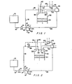
- methanol from a methanol storage tank 10 passes along pipe 12 to a fuel injection pump 14 which leads to a junction piece 16.
- One line from the junction piece (the major line) passes along pipe 1 8.
- the other line from the junction piece passes along pipe 22 to a partial vaporiser 24 where some of the methanol will be vaporised.
- Any castor oil lubricant present together with unvaporised methanol, will pass along line 19 and connect via junction 21 with the remainder of the methanol in line 18.
- the heat required for vaporising the methanol is supplied by the hot water in the engine cooling system via line 23.
- the vaporised methanol passes from the partial vaporiser 24 along pipe 26 to a heat exchanger 28 mounted in or around exhaust pipe 30 leading from a compression ignition cylinder 32.
- the cylinder has a piston 34, valve 36 in the exhaust port, and valve 38 in the inlet port of air inlet 40.
- the methanol is heated in the heat exchanger 28 and passes along pipe 42 to a catalytic converter 44 where the methanol is partially converted to dimethyl ether and passed into pipe 46.
- the catalyst is a silica modified active alumina catalyst.
- the dimethyl ether from pipe 46 enters the air inlet 40 and hence the cylinder 32 with the air. Meanwhile, in that Figure, the methanol passes from the junction 21 through pipes 18 and 48 to enter the cylinder through a separate inlet 50.
- the methanol from the junction 21 passes through a cooler 20, then along pipe 48 to enter the cylinder through inlet 50.
- the dimethyl ether from the catalytic converter 44 passes along pipe 46 to enter the cylinder 32 through a separate inlet 52.
- the dimethyl ether may pass along pipe 54 shown in broken lines to be mixed with the methanol upstream of the cooler 20 and enter the cylinder through inlet 50 dissolved in the methanol.
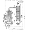
- Methanol from a methanol storage tank 10 passes along pipe 60 to junction piece 62.
- Pipe 64 from junction piece 62 leads to the electrically driven pump 66.
- Pump 66 delivers methanol via pipe 26 to a heat exchanger 28 (in the form of a boiler/superheater), mounted in or around exhaust pipe 30, leading from a compression ignition cylinder 32.
- the cylinder has a piston 34, valve 36 in the exhaust port, and valve 38 in the inlet port 40 for air inlet.
- the methanol is heated in the boiler/superheater 28 and passes along pipe 42 to a catalytic converter 44, where the methanol is partially converted to dimethylether and passed into pipe 46.
- Pipe 46 is connected to the air inlet 40 such that the dimethylether stream passes with the air through valve 38 into the cylinder 32.
- the catalyst in 44 is gamma- alumina.
- Pipe 68 from junction piece 62 connects to junction piece 70.
- An automatic lubricant injection unit injects lubricant from lubricant storage tank 72, through pipe 74, into one side of junction piece 70.
- the methanol and lubricant pass through pipe 76 to a fuel injection pump 78 which leads through pipe 48 to enter the cylinder 32 through a separate inlet 50.
- the weight hourly space velocity of methanol over the catalyst is greater than 0.2 (hour)-' and in particular can be as high as 50 (hour)-'.
- the mass of catalyst is less than 7 kg of catalyst per cylinder; in particular 0.05 kg to 0.15 kg of catalyst can be used per litre of engine capacity.
- the proportion of methanol fed to the engine via the catalytic converter can be from 5% to 50% of the total methanol flow rate to the engine.
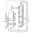
- a compression ignition engine is shown schematically in broken lines at 100.
- a support bracket 102 Mounted on the side thereof by a support bracket 102 is a catalyst conversion chamber 104.
- a boiler/superheater 106 is bolted on the side of the engine 100 by a support plate 108.
- Exhaust gas from the engine passes through a pipe (not visible) into chamber 110 and then into U-tubes 112. It passes out along pipe 114 into the centre of the boiler/superheater 106 before finally leading into exhaust pipe 116.
- a handle 118 operates baffles 120, 122 for controlling the volume of exhaust gas passing down the U-tubes 112.
- a catalyst is inserted into the chamber 104 through hatch 124.
- Liquid methanol from a storage tank enters the boiler/ superheater 106 through inlet 126, passes through finned tubes 128, 128.1, and leaves the boiler/superheater 106 as vapour through outlet 130. From here the methanol vapour passes through the catalyst which is heated by the U-tubes 112. Conversion of the methanol to dimethyl ether takes place and the dimethyl ether leaves the conversion chamber through pipe 132 which leads to the engine. Baffles are shown at 134.
Landscapes
- Engineering & Computer Science (AREA)
- Chemical & Material Sciences (AREA)
- Combustion & Propulsion (AREA)
- Mechanical Engineering (AREA)
- General Engineering & Computer Science (AREA)
- Chemical Kinetics & Catalysis (AREA)
- Output Control And Ontrol Of Special Type Engine (AREA)
- Combustion Methods Of Internal-Combustion Engines (AREA)
- Exhaust Gas After Treatment (AREA)
- Organic Low-Molecular-Weight Compounds And Preparation Thereof (AREA)
Claims (8)
Applications Claiming Priority (2)
| Application Number | Priority Date | Filing Date | Title |
|---|---|---|---|
| ZA797031 | 1979-12-27 | ||
| ZA797031 | 1979-12-27 |
Publications (2)
| Publication Number | Publication Date |
|---|---|
| EP0032003A1 EP0032003A1 (de) | 1981-07-15 |
| EP0032003B1 true EP0032003B1 (de) | 1984-11-28 |
Family
ID=25574447
Family Applications (1)
| Application Number | Title | Priority Date | Filing Date |
|---|---|---|---|
| EP80304416A Expired EP0032003B1 (de) | 1979-12-27 | 1980-12-05 | Vorrichtung zum Umwandeln von Alkoholen in Äther und Verfahren zum Betrieb bzw. zum Umbau einer Brennkraftmaschine, um in ihr den Gebrauch eines aus Alkohol und Äther bestehenden Treibstoffs zu ermöglichen |
Country Status (10)
| Country | Link |
|---|---|
| US (1) | US4422412A (de) |
| EP (1) | EP0032003B1 (de) |
| JP (1) | JPS56132447A (de) |
| AU (1) | AU541741B2 (de) |
| BR (1) | BR8008205A (de) |
| CA (1) | CA1144019A (de) |
| DE (1) | DE3069720D1 (de) |
| NO (1) | NO803864L (de) |
| NZ (1) | NZ195794A (de) |
| ZW (1) | ZW28380A1 (de) |
Families Citing this family (27)
| Publication number | Priority date | Publication date | Assignee | Title |
|---|---|---|---|---|
| US4715326A (en) * | 1986-09-08 | 1987-12-29 | Southwest Research Institute | Multicylinder catalytic engine |
| EP0419743A1 (de) * | 1989-09-29 | 1991-04-03 | Her Majesty The Queen In Right Of New Zealand | Kraftstoffversorgung und Kontrollsystem für Dieselmotoren |
| US5906664A (en) * | 1994-08-12 | 1999-05-25 | Amoco Corporation | Fuels for diesel engines |
| US6270541B1 (en) * | 1994-08-12 | 2001-08-07 | Bp Corporation North America Inc. | Diesel fuel composition |
| US5485818A (en) * | 1995-02-22 | 1996-01-23 | Navistar International Transportation Corp. | Dimethyl ether powered engine |
| EP0801225A1 (de) * | 1996-04-09 | 1997-10-15 | Jenbacher Energiesysteme Ag | Zündfluid |
| US5816228A (en) * | 1997-02-19 | 1998-10-06 | Avl Powertrain Engineering, Inc. | Fuel injection system for clean low viscosity fuels |
| RU2135798C1 (ru) * | 1997-12-22 | 1999-08-27 | Аллилуев Борис Федорович | Способ конвертирования поршневого бензинового двигателя внутреннего сгорания в дизельный двигатель |
| RU2135813C1 (ru) * | 1998-02-13 | 1999-08-27 | Аллилуев Борис Федорович | Топливная система дизеля для работы на диметиловом эфире |
| AU766420B2 (en) * | 1999-07-01 | 2003-10-16 | Haldor Topsoe A/S | Continuous dehydration of alcohol to ether and water used as fuel for diesel engines |
| DE60027675T2 (de) * | 1999-12-10 | 2006-11-09 | Haldor Topsoe A/S | Verfahren zum Betrieb einer Dieselbrennkraftmaschine |
| CN1327121C (zh) * | 2002-12-05 | 2007-07-18 | 天津大学 | 超低排放甲醇燃料发动机 |
| JP2006226172A (ja) * | 2005-02-17 | 2006-08-31 | Honda Motor Co Ltd | 圧縮着火内燃機関の制御方法 |
| JP4798093B2 (ja) * | 2006-08-04 | 2011-10-19 | 日産自動車株式会社 | 流体改質装置及びこれを用いた流体改質方法 |
| DE102008032253B4 (de) | 2008-07-09 | 2013-05-29 | Man Truck & Bus Ag | Selbstzündende Verbrennungskraftmaschine mit Ether-Fumigation der Verbrennungsluft für Fahrzeuge und Verfahren zur Ether-Fumigation der Verbrennungsluft in einer selbstzündenden Verbrennungsmaschine für Fahrzeuge |
| CN101718224B (zh) * | 2009-12-07 | 2012-06-27 | 奇瑞汽车股份有限公司 | 一种压燃式甲醇发动机 |
| BR112012024736A2 (pt) * | 2010-03-31 | 2019-09-24 | Haldor Tops0E As | método e sistema para operar um motor de ignição por compressão em combustíveis primários contendo álcool |
| EP2553237A1 (de) * | 2010-03-31 | 2013-02-06 | Haldor Topsøe A/S | Verfahren und system für den betrieb eines selbstzündungsmotors mit alkoholhaltigen kraftstoffen |
| BR112012024588A2 (pt) * | 2010-03-31 | 2017-10-03 | Haldor Topsoe As | Método e sistema para operar um motor de ignição por pressão |
| HRP20180461T1 (hr) | 2010-11-25 | 2018-04-20 | Gane Energy & Resources Pty Ltd | Postupak za napajanje motora s kompresijskim paljenjem pomoću goriva koje sadrži metanol |
| US20120247002A1 (en) | 2011-04-01 | 2012-10-04 | Christophe Duwig | process for preparing a fuel for automotive applications, stationary engines and marine applications by catalytic liquid phase alcohol conversion and a compact device for carrying out the process |
| US8991368B2 (en) | 2012-02-23 | 2015-03-31 | Discovery Fuel Technologies, Llc | Oxygenate compound synthesis device, systems including the device, and methods of using the same |
| HRP20180633T1 (hr) * | 2012-05-25 | 2018-06-01 | Gane Energy & Resources Pty Ltd | Postupak za pripremu i provedbu smjese goriva |
| DE102012014755A1 (de) * | 2012-07-26 | 2014-05-15 | Man Truck & Bus Ag | Verfahren und Vorrichtung zur Umwandlung eines Alkohols in ein Kraftstoffgemisch |
| DE102012017718B4 (de) * | 2012-09-07 | 2021-06-17 | Edgar Harzfeld | Verfahren und Vorrichtung zur Verwendung von Methanol in einem Verbrennungsmotor mit Selbstzündung |
| US11643987B2 (en) | 2021-09-07 | 2023-05-09 | Caterpillar Inc. | In-line generation of pilot fuel for power systems |
| US12078115B1 (en) * | 2023-06-20 | 2024-09-03 | Caterpillar Inc. | Systems and methods for pilot fuel synthesis using engine waste heat |
Citations (3)
| Publication number | Priority date | Publication date | Assignee | Title |
|---|---|---|---|---|
| AT22235B (de) * | 1904-04-20 | 1905-11-25 | Cie Du Carburateur Claudel | Verdampfer für Kohlenwasserstoffe. |
| DE365115C (de) * | 1922-02-23 | 1922-12-08 | Franz Fischer Dr | Verfahren zum Betriebe von Explosions- oder Verbrennungsmotoren |
| EP0019340A1 (de) * | 1979-05-17 | 1980-11-26 | Stamicarbon B.V. | Verfahren zum Betrieb einer Dieselmaschine mit Methanol und/oder Äthanol als Hauptbrennstoff |
Family Cites Families (17)
| Publication number | Priority date | Publication date | Assignee | Title |
|---|---|---|---|---|
| DE22255C (de) * | G. rothgiesser in Bielefeld | Neuerung an Tretwerken für Nähmaschinen u. s. w. zur Vermeidung der todten Punkte | ||
| DE307913C (de) * | ||||
| US2513769A (en) * | 1947-04-24 | 1950-07-04 | Samuel H White | Gaseous fuel mixtures |
| US2876750A (en) * | 1954-01-21 | 1959-03-10 | Phillips Petroleum Co | Fuel containing anti-icing additives |
| US3660059A (en) * | 1970-04-13 | 1972-05-02 | Dow Chemical Co | Fuel gas composition |
| US3849082A (en) * | 1970-06-26 | 1974-11-19 | Chevron Res | Hydrocarbon conversion process |
| ZA735837B (en) * | 1973-08-07 | 1974-11-27 | Fuel Res Inst | Improvements in and relating to internal combustion engines |
| DE2410644A1 (de) * | 1974-03-06 | 1975-09-18 | Reinhold Dipl Ing Schmidt | Anordnungen an brennkraftmaschinen und/oder feuerungsanlagen bei methanol-betrieb |
| JPS5228447B2 (de) * | 1974-03-06 | 1977-07-27 | ||
| DE2418423A1 (de) * | 1974-04-17 | 1975-10-30 | Daimler Benz Ag | Verfahren zum betrieb einer brennkraftmaschine und vorrichtung zur durchfuehrung des verfahrens |
| DE2542681C2 (de) * | 1975-09-25 | 1983-04-14 | Daimler-Benz Ag, 7000 Stuttgart | Spaltgaserzeugung für Verbrennungskraftmaschinen |
| JPS5257425A (en) * | 1975-11-05 | 1977-05-11 | Nissan Motor Co Ltd | Reforming equipment for gas engine reformed |
| GB1513051A (en) | 1976-01-09 | 1978-06-07 | Wilkes J | Spark-ignition internal combustion engines |
| US4156698A (en) * | 1977-05-05 | 1979-05-29 | Mobil Oil Corporation | Conversion of alcohols or ethers using rare earth crystalline aluminosilicate in an alumina matrix |
| JPS5413231A (en) * | 1977-07-01 | 1979-01-31 | Takeda Riken Ind Co Ltd | Memory tester |
| US4175210A (en) * | 1978-06-19 | 1979-11-20 | Gulf Research And Development Company | Etherification process |
| US4282835A (en) * | 1979-07-02 | 1981-08-11 | Wm. D. Peterson & Associates | Internal combustion engine with gas synthesizer |
-
1980
- 1980-11-26 ZW ZW283/80A patent/ZW28380A1/xx unknown
- 1980-12-05 EP EP80304416A patent/EP0032003B1/de not_active Expired
- 1980-12-05 DE DE8080304416T patent/DE3069720D1/de not_active Expired
- 1980-12-08 CA CA000366337A patent/CA1144019A/en not_active Expired
- 1980-12-09 NZ NZ195794A patent/NZ195794A/xx unknown
- 1980-12-11 AU AU65285/80A patent/AU541741B2/en not_active Ceased
- 1980-12-15 BR BR8008205A patent/BR8008205A/pt unknown
- 1980-12-18 NO NO803864A patent/NO803864L/no unknown
- 1980-12-25 JP JP18497180A patent/JPS56132447A/ja active Pending
-
1982
- 1982-11-16 US US06/442,001 patent/US4422412A/en not_active Expired - Fee Related
Patent Citations (3)
| Publication number | Priority date | Publication date | Assignee | Title |
|---|---|---|---|---|
| AT22235B (de) * | 1904-04-20 | 1905-11-25 | Cie Du Carburateur Claudel | Verdampfer für Kohlenwasserstoffe. |
| DE365115C (de) * | 1922-02-23 | 1922-12-08 | Franz Fischer Dr | Verfahren zum Betriebe von Explosions- oder Verbrennungsmotoren |
| EP0019340A1 (de) * | 1979-05-17 | 1980-11-26 | Stamicarbon B.V. | Verfahren zum Betrieb einer Dieselmaschine mit Methanol und/oder Äthanol als Hauptbrennstoff |
Also Published As
| Publication number | Publication date |
|---|---|
| DE3069720D1 (en) | 1985-01-10 |
| CA1144019A (en) | 1983-04-05 |
| NO803864L (no) | 1981-06-29 |
| BR8008205A (pt) | 1981-06-30 |
| EP0032003A1 (de) | 1981-07-15 |
| AU541741B2 (en) | 1985-01-17 |
| US4422412A (en) | 1983-12-27 |
| NZ195794A (en) | 1983-05-10 |
| ZW28380A1 (en) | 1981-07-22 |
| AU6528580A (en) | 1981-07-02 |
| JPS56132447A (en) | 1981-10-16 |
Similar Documents
| Publication | Publication Date | Title |
|---|---|---|
| EP0032003B1 (de) | Vorrichtung zum Umwandeln von Alkoholen in Äther und Verfahren zum Betrieb bzw. zum Umbau einer Brennkraftmaschine, um in ihr den Gebrauch eines aus Alkohol und Äther bestehenden Treibstoffs zu ermöglichen | |
| EP0102956B1 (de) | Verfahren zum betrieb einer brennkraftmaschine mit alternativen brennstoffen und brennkraftmaschine für alternative brennstoffe | |
| US4567857A (en) | Combustion engine system | |
| EP0700483B1 (de) | Verfahren und vorrichtung zur änderung eines brennstoffes zur verringerung von aus brennkraftmaschinen ausgestossenen schadstoffen | |
| US4750453A (en) | Internal combustion engine | |
| CA1327878C (en) | Enhanced performance of alcohol fueled engine during cold conditions | |
| US5085176A (en) | Method of and apparatus for generating and injecting hydrogen into an engine | |
| US4478177A (en) | Internal combustion engine | |
| US4416224A (en) | Internal combustion engine | |
| US8820269B2 (en) | Method and system for operating a compression ignition engine on alcohol containing primary fuels | |
| US4475484A (en) | Exhaust manifold for an internal combustion engine, apparatus for the catalytic transformation of fuel and improved internal combustion engine | |
| US3951124A (en) | Pollution reducing and fuel saving device | |
| US4008692A (en) | Vehicle-mounted gaseous fuel generator | |
| US5775308A (en) | Internal combustion engine | |
| US4338906A (en) | Fuel charge preheater | |
| US4157700A (en) | Pre-vaporization system | |
| HU201982B (en) | Internal combustion power machine | |
| US4748961A (en) | Internal combustion engines | |
| US4106455A (en) | Vaporizer system for gasoline engines | |
| Pettersson et al. | Onboard hydrogen generation by methanol decomposition for the cold start of neat methanol engines | |
| JPH06249089A (ja) | 車載用ジメチルエーテル発生装置 | |
| KR20190106534A (ko) | 내연기관의 배기가스 정화 장치 및 방법 | |
| CN2411345Y (zh) | 柴油发动机消烟净化装置 | |
| CN2498347Y (zh) | 预热式甲醇-氢燃料发动机 | |
| US20070022976A1 (en) | Performance of interal combustion engines |
Legal Events
| Date | Code | Title | Description |
|---|---|---|---|
| PUAI | Public reference made under article 153(3) epc to a published international application that has entered the european phase |
Free format text: ORIGINAL CODE: 0009012 |
|
| AK | Designated contracting states |
Designated state(s): BE DE FR GB IT NL SE |
|
| 17P | Request for examination filed |
Effective date: 19811125 |
|
| ITF | It: translation for a ep patent filed | ||
| GRAA | (expected) grant |
Free format text: ORIGINAL CODE: 0009210 |
|
| AK | Designated contracting states |
Designated state(s): BE DE FR GB IT NL SE |
|
| PGFP | Annual fee paid to national office [announced via postgrant information from national office to epo] |
Ref country code: FR Payment date: 19841210 Year of fee payment: 5 |
|
| PGFP | Annual fee paid to national office [announced via postgrant information from national office to epo] |
Ref country code: SE Payment date: 19841231 Year of fee payment: 5 Ref country code: BE Payment date: 19841231 Year of fee payment: 5 |
|
| REF | Corresponds to: |
Ref document number: 3069720 Country of ref document: DE Date of ref document: 19850110 |
|
| ET | Fr: translation filed | ||
| PLBE | No opposition filed within time limit |
Free format text: ORIGINAL CODE: 0009261 |
|
| STAA | Information on the status of an ep patent application or granted ep patent |
Free format text: STATUS: NO OPPOSITION FILED WITHIN TIME LIMIT |
|
| 26N | No opposition filed | ||
| PGFP | Annual fee paid to national office [announced via postgrant information from national office to epo] |
Ref country code: NL Payment date: 19871231 Year of fee payment: 8 |
|
| PG25 | Lapsed in a contracting state [announced via postgrant information from national office to epo] |
Ref country code: GB Effective date: 19891205 |
|
| PG25 | Lapsed in a contracting state [announced via postgrant information from national office to epo] |
Ref country code: SE Effective date: 19891206 |
|
| PG25 | Lapsed in a contracting state [announced via postgrant information from national office to epo] |
Ref country code: BE Effective date: 19891231 |
|
| BERE | Be: lapsed |
Owner name: AECI LTD Effective date: 19891231 |
|
| PG25 | Lapsed in a contracting state [announced via postgrant information from national office to epo] |
Ref country code: NL Effective date: 19900701 |
|
| GBPC | Gb: european patent ceased through non-payment of renewal fee | ||
| NLV4 | Nl: lapsed or anulled due to non-payment of the annual fee | ||
| PG25 | Lapsed in a contracting state [announced via postgrant information from national office to epo] |
Ref country code: FR Effective date: 19900831 |
|
| PG25 | Lapsed in a contracting state [announced via postgrant information from national office to epo] |
Ref country code: DE Effective date: 19900901 |
|
| REG | Reference to a national code |
Ref country code: FR Ref legal event code: ST |
|
| EUG | Se: european patent has lapsed |
Ref document number: 80304416.3 Effective date: 19900829 |