EP0102956B1 - Verfahren zum betrieb einer brennkraftmaschine mit alternativen brennstoffen und brennkraftmaschine für alternative brennstoffe - Google Patents
Verfahren zum betrieb einer brennkraftmaschine mit alternativen brennstoffen und brennkraftmaschine für alternative brennstoffe Download PDFInfo
- Publication number
- EP0102956B1 EP0102956B1 EP82903157A EP82903157A EP0102956B1 EP 0102956 B1 EP0102956 B1 EP 0102956B1 EP 82903157 A EP82903157 A EP 82903157A EP 82903157 A EP82903157 A EP 82903157A EP 0102956 B1 EP0102956 B1 EP 0102956B1
- Authority
- EP
- European Patent Office
- Prior art keywords
- fuel
- cylinder
- internal combustion
- combustion engine
- running
- Prior art date
- Legal status (The legal status is an assumption and is not a legal conclusion. Google has not performed a legal analysis and makes no representation as to the accuracy of the status listed.)
- Expired
Links
- 239000000446 fuel Substances 0.000 title claims abstract description 74
- 238000002485 combustion reaction Methods 0.000 title claims abstract description 24
- 238000000034 method Methods 0.000 title claims abstract description 6
- 238000002347 injection Methods 0.000 claims abstract description 26
- 239000007924 injection Substances 0.000 claims abstract description 26
- XLYOFNOQVPJJNP-UHFFFAOYSA-N water Substances O XLYOFNOQVPJJNP-UHFFFAOYSA-N 0.000 claims abstract description 24
- 239000000203 mixture Substances 0.000 claims abstract description 6
- TVMXDCGIABBOFY-UHFFFAOYSA-N octane Chemical compound CCCCCCCC TVMXDCGIABBOFY-UHFFFAOYSA-N 0.000 claims abstract description 5
- 239000003795 chemical substances by application Substances 0.000 claims abstract description 3
- 238000007710 freezing Methods 0.000 claims description 2
- 238000010438 heat treatment Methods 0.000 claims 2
- OKKJLVBELUTLKV-UHFFFAOYSA-N Methanol Chemical compound OC OKKJLVBELUTLKV-UHFFFAOYSA-N 0.000 abstract description 9
- 230000006835 compression Effects 0.000 abstract description 9
- 238000007906 compression Methods 0.000 abstract description 9
- 239000007789 gas Substances 0.000 abstract description 9
- LFQSCWFLJHTTHZ-UHFFFAOYSA-N Ethanol Chemical compound CCO LFQSCWFLJHTTHZ-UHFFFAOYSA-N 0.000 abstract description 7
- 239000003502 gasoline Substances 0.000 abstract description 5
- 239000002283 diesel fuel Substances 0.000 abstract description 4
- 239000012188 paraffin wax Substances 0.000 abstract description 2
- 230000008020 evaporation Effects 0.000 abstract 1
- 238000001704 evaporation Methods 0.000 abstract 1
- 230000001105 regulatory effect Effects 0.000 description 4
- MWUXSHHQAYIFBG-UHFFFAOYSA-N nitrogen oxide Inorganic materials O=[N] MWUXSHHQAYIFBG-UHFFFAOYSA-N 0.000 description 3
- 239000003921 oil Substances 0.000 description 3
- CURLTUGMZLYLDI-UHFFFAOYSA-N Carbon dioxide Chemical compound O=C=O CURLTUGMZLYLDI-UHFFFAOYSA-N 0.000 description 2
- 229910000953 kanthal Inorganic materials 0.000 description 2
- 238000004519 manufacturing process Methods 0.000 description 2
- 239000000463 material Substances 0.000 description 2
- UGFAIRIUMAVXCW-UHFFFAOYSA-N Carbon monoxide Chemical compound [O+]#[C-] UGFAIRIUMAVXCW-UHFFFAOYSA-N 0.000 description 1
- UFHFLCQGNIYNRP-UHFFFAOYSA-N Hydrogen Chemical compound [H][H] UFHFLCQGNIYNRP-UHFFFAOYSA-N 0.000 description 1
- 239000001569 carbon dioxide Substances 0.000 description 1
- 229910002092 carbon dioxide Inorganic materials 0.000 description 1
- 229910002091 carbon monoxide Inorganic materials 0.000 description 1
- 229910010293 ceramic material Inorganic materials 0.000 description 1
- 238000010276 construction Methods 0.000 description 1
- 230000001419 dependent effect Effects 0.000 description 1
- 230000008016 vaporization Effects 0.000 description 1
Images


Classifications
-
- F—MECHANICAL ENGINEERING; LIGHTING; HEATING; WEAPONS; BLASTING
- F02—COMBUSTION ENGINES; HOT-GAS OR COMBUSTION-PRODUCT ENGINE PLANTS
- F02M—SUPPLYING COMBUSTION ENGINES IN GENERAL WITH COMBUSTIBLE MIXTURES OR CONSTITUENTS THEREOF
- F02M25/00—Engine-pertinent apparatus for adding non-fuel substances or small quantities of secondary fuel to combustion-air, main fuel or fuel-air mixture
- F02M25/022—Adding fuel and water emulsion, water or steam
- F02M25/025—Adding water
- F02M25/028—Adding water into the charge intakes
-
- F—MECHANICAL ENGINEERING; LIGHTING; HEATING; WEAPONS; BLASTING
- F02—COMBUSTION ENGINES; HOT-GAS OR COMBUSTION-PRODUCT ENGINE PLANTS
- F02B—INTERNAL-COMBUSTION PISTON ENGINES; COMBUSTION ENGINES IN GENERAL
- F02B69/00—Internal-combustion engines convertible into other combustion-engine type, not provided for in F02B11/00; Internal-combustion engines of different types characterised by constructions facilitating use of same main engine-parts in different types
- F02B69/02—Internal-combustion engines convertible into other combustion-engine type, not provided for in F02B11/00; Internal-combustion engines of different types characterised by constructions facilitating use of same main engine-parts in different types for different fuel types, other than engines indifferent to fuel consumed, e.g. convertible from light to heavy fuel
- F02B69/04—Internal-combustion engines convertible into other combustion-engine type, not provided for in F02B11/00; Internal-combustion engines of different types characterised by constructions facilitating use of same main engine-parts in different types for different fuel types, other than engines indifferent to fuel consumed, e.g. convertible from light to heavy fuel for gaseous and non-gaseous fuels
-
- F—MECHANICAL ENGINEERING; LIGHTING; HEATING; WEAPONS; BLASTING
- F02—COMBUSTION ENGINES; HOT-GAS OR COMBUSTION-PRODUCT ENGINE PLANTS
- F02D—CONTROLLING COMBUSTION ENGINES
- F02D19/00—Controlling engines characterised by their use of non-liquid fuels, pluralities of fuels, or non-fuel substances added to the combustible mixtures
- F02D19/06—Controlling engines characterised by their use of non-liquid fuels, pluralities of fuels, or non-fuel substances added to the combustible mixtures peculiar to engines working with pluralities of fuels, e.g. alternatively with light and heavy fuel oil, other than engines indifferent to the fuel consumed
- F02D19/0602—Control of components of the fuel supply system
- F02D19/0605—Control of components of the fuel supply system to adjust the fuel pressure or temperature
-
- F—MECHANICAL ENGINEERING; LIGHTING; HEATING; WEAPONS; BLASTING
- F02—COMBUSTION ENGINES; HOT-GAS OR COMBUSTION-PRODUCT ENGINE PLANTS
- F02D—CONTROLLING COMBUSTION ENGINES
- F02D19/00—Controlling engines characterised by their use of non-liquid fuels, pluralities of fuels, or non-fuel substances added to the combustible mixtures
- F02D19/06—Controlling engines characterised by their use of non-liquid fuels, pluralities of fuels, or non-fuel substances added to the combustible mixtures peculiar to engines working with pluralities of fuels, e.g. alternatively with light and heavy fuel oil, other than engines indifferent to the fuel consumed
- F02D19/0626—Measuring or estimating parameters related to the fuel supply system
- F02D19/0628—Determining the fuel pressure, temperature or flow, the fuel tank fill level or a valve position
-
- F—MECHANICAL ENGINEERING; LIGHTING; HEATING; WEAPONS; BLASTING
- F02—COMBUSTION ENGINES; HOT-GAS OR COMBUSTION-PRODUCT ENGINE PLANTS
- F02D—CONTROLLING COMBUSTION ENGINES
- F02D19/00—Controlling engines characterised by their use of non-liquid fuels, pluralities of fuels, or non-fuel substances added to the combustible mixtures
- F02D19/06—Controlling engines characterised by their use of non-liquid fuels, pluralities of fuels, or non-fuel substances added to the combustible mixtures peculiar to engines working with pluralities of fuels, e.g. alternatively with light and heavy fuel oil, other than engines indifferent to the fuel consumed
- F02D19/0639—Controlling engines characterised by their use of non-liquid fuels, pluralities of fuels, or non-fuel substances added to the combustible mixtures peculiar to engines working with pluralities of fuels, e.g. alternatively with light and heavy fuel oil, other than engines indifferent to the fuel consumed characterised by the type of fuels
- F02D19/0649—Liquid fuels having different boiling temperatures, volatilities, densities, viscosities, cetane or octane numbers
- F02D19/0652—Biofuels, e.g. plant oils
- F02D19/0655—Biofuels, e.g. plant oils at least one fuel being an alcohol, e.g. ethanol
-
- F—MECHANICAL ENGINEERING; LIGHTING; HEATING; WEAPONS; BLASTING
- F02—COMBUSTION ENGINES; HOT-GAS OR COMBUSTION-PRODUCT ENGINE PLANTS
- F02D—CONTROLLING COMBUSTION ENGINES
- F02D19/00—Controlling engines characterised by their use of non-liquid fuels, pluralities of fuels, or non-fuel substances added to the combustible mixtures
- F02D19/06—Controlling engines characterised by their use of non-liquid fuels, pluralities of fuels, or non-fuel substances added to the combustible mixtures peculiar to engines working with pluralities of fuels, e.g. alternatively with light and heavy fuel oil, other than engines indifferent to the fuel consumed
- F02D19/0663—Details on the fuel supply system, e.g. tanks, valves, pipes, pumps, rails, injectors or mixers
- F02D19/0673—Valves; Pressure or flow regulators; Mixers
- F02D19/0678—Pressure or flow regulators therefor; Fuel metering valves therefor
-
- F—MECHANICAL ENGINEERING; LIGHTING; HEATING; WEAPONS; BLASTING
- F02—COMBUSTION ENGINES; HOT-GAS OR COMBUSTION-PRODUCT ENGINE PLANTS
- F02D—CONTROLLING COMBUSTION ENGINES
- F02D19/00—Controlling engines characterised by their use of non-liquid fuels, pluralities of fuels, or non-fuel substances added to the combustible mixtures
- F02D19/06—Controlling engines characterised by their use of non-liquid fuels, pluralities of fuels, or non-fuel substances added to the combustible mixtures peculiar to engines working with pluralities of fuels, e.g. alternatively with light and heavy fuel oil, other than engines indifferent to the fuel consumed
- F02D19/0663—Details on the fuel supply system, e.g. tanks, valves, pipes, pumps, rails, injectors or mixers
- F02D19/0686—Injectors
-
- F—MECHANICAL ENGINEERING; LIGHTING; HEATING; WEAPONS; BLASTING
- F02—COMBUSTION ENGINES; HOT-GAS OR COMBUSTION-PRODUCT ENGINE PLANTS
- F02D—CONTROLLING COMBUSTION ENGINES
- F02D19/00—Controlling engines characterised by their use of non-liquid fuels, pluralities of fuels, or non-fuel substances added to the combustible mixtures
- F02D19/06—Controlling engines characterised by their use of non-liquid fuels, pluralities of fuels, or non-fuel substances added to the combustible mixtures peculiar to engines working with pluralities of fuels, e.g. alternatively with light and heavy fuel oil, other than engines indifferent to the fuel consumed
- F02D19/0663—Details on the fuel supply system, e.g. tanks, valves, pipes, pumps, rails, injectors or mixers
- F02D19/0697—Arrangement of fuel supply systems on engines or vehicle bodies; Components of the fuel supply system being combined with another device
-
- F—MECHANICAL ENGINEERING; LIGHTING; HEATING; WEAPONS; BLASTING
- F02—COMBUSTION ENGINES; HOT-GAS OR COMBUSTION-PRODUCT ENGINE PLANTS
- F02D—CONTROLLING COMBUSTION ENGINES
- F02D19/00—Controlling engines characterised by their use of non-liquid fuels, pluralities of fuels, or non-fuel substances added to the combustible mixtures
- F02D19/06—Controlling engines characterised by their use of non-liquid fuels, pluralities of fuels, or non-fuel substances added to the combustible mixtures peculiar to engines working with pluralities of fuels, e.g. alternatively with light and heavy fuel oil, other than engines indifferent to the fuel consumed
- F02D19/08—Controlling engines characterised by their use of non-liquid fuels, pluralities of fuels, or non-fuel substances added to the combustible mixtures peculiar to engines working with pluralities of fuels, e.g. alternatively with light and heavy fuel oil, other than engines indifferent to the fuel consumed simultaneously using pluralities of fuels
-
- F—MECHANICAL ENGINEERING; LIGHTING; HEATING; WEAPONS; BLASTING
- F02—COMBUSTION ENGINES; HOT-GAS OR COMBUSTION-PRODUCT ENGINE PLANTS
- F02D—CONTROLLING COMBUSTION ENGINES
- F02D19/00—Controlling engines characterised by their use of non-liquid fuels, pluralities of fuels, or non-fuel substances added to the combustible mixtures
- F02D19/12—Controlling engines characterised by their use of non-liquid fuels, pluralities of fuels, or non-fuel substances added to the combustible mixtures peculiar to engines working with non-fuel substances or with anti-knock agents, e.g. with anti-knock fuel
-
- F—MECHANICAL ENGINEERING; LIGHTING; HEATING; WEAPONS; BLASTING
- F02—COMBUSTION ENGINES; HOT-GAS OR COMBUSTION-PRODUCT ENGINE PLANTS
- F02M—SUPPLYING COMBUSTION ENGINES IN GENERAL WITH COMBUSTIBLE MIXTURES OR CONSTITUENTS THEREOF
- F02M31/00—Apparatus for thermally treating combustion-air, fuel, or fuel-air mixture
- F02M31/02—Apparatus for thermally treating combustion-air, fuel, or fuel-air mixture for heating
- F02M31/16—Other apparatus for heating fuel
- F02M31/18—Other apparatus for heating fuel to vaporise fuel
-
- F—MECHANICAL ENGINEERING; LIGHTING; HEATING; WEAPONS; BLASTING
- F02—COMBUSTION ENGINES; HOT-GAS OR COMBUSTION-PRODUCT ENGINE PLANTS
- F02B—INTERNAL-COMBUSTION PISTON ENGINES; COMBUSTION ENGINES IN GENERAL
- F02B1/00—Engines characterised by fuel-air mixture compression
- F02B1/02—Engines characterised by fuel-air mixture compression with positive ignition
- F02B1/04—Engines characterised by fuel-air mixture compression with positive ignition with fuel-air mixture admission into cylinder
-
- F—MECHANICAL ENGINEERING; LIGHTING; HEATING; WEAPONS; BLASTING
- F02—COMBUSTION ENGINES; HOT-GAS OR COMBUSTION-PRODUCT ENGINE PLANTS
- F02B—INTERNAL-COMBUSTION PISTON ENGINES; COMBUSTION ENGINES IN GENERAL
- F02B75/00—Other engines
- F02B75/12—Other methods of operation
- F02B2075/125—Direct injection in the combustion chamber for spark ignition engines, i.e. not in pre-combustion chamber
-
- F—MECHANICAL ENGINEERING; LIGHTING; HEATING; WEAPONS; BLASTING
- F02—COMBUSTION ENGINES; HOT-GAS OR COMBUSTION-PRODUCT ENGINE PLANTS
- F02B—INTERNAL-COMBUSTION PISTON ENGINES; COMBUSTION ENGINES IN GENERAL
- F02B3/00—Engines characterised by air compression and subsequent fuel addition
- F02B3/06—Engines characterised by air compression and subsequent fuel addition with compression ignition
-
- Y—GENERAL TAGGING OF NEW TECHNOLOGICAL DEVELOPMENTS; GENERAL TAGGING OF CROSS-SECTIONAL TECHNOLOGIES SPANNING OVER SEVERAL SECTIONS OF THE IPC; TECHNICAL SUBJECTS COVERED BY FORMER USPC CROSS-REFERENCE ART COLLECTIONS [XRACs] AND DIGESTS
- Y02—TECHNOLOGIES OR APPLICATIONS FOR MITIGATION OR ADAPTATION AGAINST CLIMATE CHANGE
- Y02T—CLIMATE CHANGE MITIGATION TECHNOLOGIES RELATED TO TRANSPORTATION
- Y02T10/00—Road transport of goods or passengers
- Y02T10/10—Internal combustion engine [ICE] based vehicles
- Y02T10/12—Improving ICE efficiencies
-
- Y—GENERAL TAGGING OF NEW TECHNOLOGICAL DEVELOPMENTS; GENERAL TAGGING OF CROSS-SECTIONAL TECHNOLOGIES SPANNING OVER SEVERAL SECTIONS OF THE IPC; TECHNICAL SUBJECTS COVERED BY FORMER USPC CROSS-REFERENCE ART COLLECTIONS [XRACs] AND DIGESTS
- Y02—TECHNOLOGIES OR APPLICATIONS FOR MITIGATION OR ADAPTATION AGAINST CLIMATE CHANGE
- Y02T—CLIMATE CHANGE MITIGATION TECHNOLOGIES RELATED TO TRANSPORTATION
- Y02T10/00—Road transport of goods or passengers
- Y02T10/10—Internal combustion engine [ICE] based vehicles
- Y02T10/30—Use of alternative fuels, e.g. biofuels
Definitions
- This invention refers to a method of running an internal combustion engine, at which each of the cylinders can be fed with an extra medium besides the fuel needed for running the engine, the fuel being proportioned and distributed to each motor cylinder in relation to the amount of air suched up.
- the invention also refers to a combustion engine for running with alternative fuels.
- DE-A-2 831 694 is disclosed an internal combustion engine, in which an extra medium, e.g. water besides the fuel is supplied to the cylinder. The object is to improve the combustion and the utilization of the fuel.
- the purpose of this invention is to provide a method of running an internal combustion engine with alternative fuels, as high or low octane gasoline, paraffin, diesel oil, ethanol, methanol or the like and/or mixtures thereof at unchanged comprssion ratio.
- alternative fuels as high or low octane gasoline, paraffin, diesel oil, ethanol, methanol or the like and/or mixtures thereof at unchanged comprssion ratio.
- the running of the engine shall be non-detonating, provide an improved fuel-economy, cleaner exhaust gases and not shorten the lifetime of the engine.
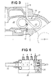
- the numeral 11 refers to a cylinder head of an internal combustion engine
- 12 the inlet to the combustion room 13
- 14 is an inlet valve
- 15 is the inlet manifold.
- a distance piece 17 which to its outer shape looks like the normal gasket used between these both parts.
- the fuel pipe comprise a fitting 19 connected to a fuel feeding device 20, a heat exchanger loop 21, which is partly positioned in the outlet channel in the exhaust gas channel of the resp. cylinder 22 and partly in the exhaust manifold 23.
- the fuel pipe further comprise an injection part 24, which is directed towards the gap of the inlet valve 14 in such a manner that a flat tangential angle is achieved with respect to the cylinder wall 26.
- the distance piece 17 is also provided with a feeding line 27 which is fitted to a second feeding device 28 coupled in series with the feeding device 20 and feeding the engine with another medium, by way of example cold water.
- the feeding line 27 is in the inlet channel equipped with a nozzle 29, which is directed at a steeper angle than the injection part 24, towards the gap of the inlet valve.
- the venturi tube of the nozzle 29 has a relatively small opening, causing a thin jet of water.
- the fuel feeding device 20 and the water feeding device 28, which are of the same principal construction distribute the fuel and the water respectively in relation to the amount of air sucked into the motor cylinders.
- a distributing valve 30 which is pivoted about its longitudinal axis distributes the fuel and the water (if needed) dependent on the pivoting movement of the valve to the respective cylinder through the fitting 19 of the fuel pipe 18 and the feeding line 27 resp.
- Both distributing valves 30 of the feeding devices 20 and 28, are joined together and are both regulated by a vacuum diaphragm 31 which through the line 32 communicates with a venturi 33 in the air intake 15, which as seen in the direction of the air flow is positioned in front of the throttle 34.
- The.distributor casing 35 of the feeding devices 20, 28 is pivotally mounted about the distributor valve 30 for adjusting the fuel amount.
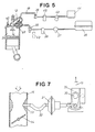
- Fig. 8 shows how the evaporated fuel is conveyed from the exhaust side over the cylinder head to the inlet side.
- the tube connection between the exhaust and the intake side can possibly be made by a tube of a resistance material (i.e. Kanthal) and thus be heated electrically or insulated by a ceramic material.
- a resistance material i.e. Kanthal
- the heat exchanger 21 can be mounted directly in the outlet manifold as shown in fig. 10 and 11.
- the fuel is pumped in a conventional manner by a standard fuel pump 37 from the tank 38 through a fuel filter 39 and if needed a pressure accumulator 40 to the feeding device 20.
- the fuel is proportioned and distributed in the feeding device and conveyed through the fuel pipe to the heat exchanger 21 in the outlet chaannel 22, 23, where the fuel is heated up to a temperature above its flame temperature.
- extra heat may be added to the fuel by an electric heater, for example by making injection part 24 of the fuel lines 18 of a resistance material (i.e. Kanthal), or by means of exhaust gases.
- the evaporated fuel will be injected in a relative flat path towards the cylinder wall 26 where the fuel will circulate in a spiral passing the spark plug 42 as a final phase of the injection stroke.
- Water is pumped by a water pump 43 from the water tank 44 by way of the filter 45 to the feeding-device 28.
- the water distribution line 27 from the feeding device 28, is with its nozzle portion located in the intake channel 12 arranged in such an angle that the water jet will enter at a steeper angle than the injected fuel.
- the fine water jet from the nozzle portion 29 will enter in a spiral inside the path of the fuel.
- the purpose of the water injection is to absorb excess heat of compression especially when using low-octane fuel and to actively take part in the combustion by reducing water with carbon monoxide to hydrogen gas and carbon dioxide and to reduce the nitrogen oxides. This contributes to a cleaner engine and cleaner exhaust gases.
Landscapes
- Engineering & Computer Science (AREA)
- Chemical & Material Sciences (AREA)
- Combustion & Propulsion (AREA)
- Mechanical Engineering (AREA)
- General Engineering & Computer Science (AREA)
- Oil, Petroleum & Natural Gas (AREA)
- Life Sciences & Earth Sciences (AREA)
- Biodiversity & Conservation Biology (AREA)
- Biotechnology (AREA)
- Botany (AREA)
- Sustainable Development (AREA)
- Sustainable Energy (AREA)
- Output Control And Ontrol Of Special Type Engine (AREA)
- Combustion Methods Of Internal-Combustion Engines (AREA)
- Fuel-Injection Apparatus (AREA)
Claims (7)
Priority Applications (1)
| Application Number | Priority Date | Filing Date | Title |
|---|---|---|---|
| AT82903157T ATE31965T1 (de) | 1981-10-16 | 1982-10-15 | Verfahren zum betrieb einer brennkraftmaschine mit alternativen brennstoffen und brennkraftmaschine fuer alternative brennstoffe. |
Applications Claiming Priority (2)
| Application Number | Priority Date | Filing Date | Title |
|---|---|---|---|
| SE8106113 | 1981-10-16 | ||
| SE8106113A SE431009B (sv) | 1981-10-16 | 1981-10-16 | Sett att driva en forbrenningsmotor med alternativa brenslen och forbrenningsmotor for drift med alternativa brenslen |
Publications (2)
| Publication Number | Publication Date |
|---|---|
| EP0102956A1 EP0102956A1 (de) | 1984-03-21 |
| EP0102956B1 true EP0102956B1 (de) | 1988-01-13 |
Family
ID=20344806
Family Applications (1)
| Application Number | Title | Priority Date | Filing Date |
|---|---|---|---|
| EP82903157A Expired EP0102956B1 (de) | 1981-10-16 | 1982-10-15 | Verfahren zum betrieb einer brennkraftmaschine mit alternativen brennstoffen und brennkraftmaschine für alternative brennstoffe |
Country Status (5)
| Country | Link |
|---|---|
| US (2) | US4548187A (de) |
| EP (1) | EP0102956B1 (de) |
| DE (1) | DE3277976D1 (de) |
| SE (1) | SE431009B (de) |
| WO (1) | WO1983001486A1 (de) |
Families Citing this family (35)
| Publication number | Priority date | Publication date | Assignee | Title |
|---|---|---|---|---|
| US4779576A (en) * | 1982-07-29 | 1988-10-25 | Stephen Masiuk | Water cooled scavenged crankcase type otto internal combustion engine |
| SE442043B (sv) * | 1983-09-09 | 1985-11-25 | Volvo Ab | Turboladdad forbrenningsmotor med vatteninsprutning |
| SE8604448D0 (sv) * | 1986-10-20 | 1986-10-20 | John Olsson | Anordning vid forbrenningsmotorer |
| JPH076458B2 (ja) * | 1988-06-17 | 1995-01-30 | 三岬商機有限会社 | 内燃機関における高温水噴射装置 |
| US5370098A (en) * | 1991-04-20 | 1994-12-06 | Yamaha Hatsudoki Kabushiki Kaisha | Air intake system for gas fueled engine |
| US5228423A (en) * | 1991-10-12 | 1993-07-20 | Honda Giken Kogyo Kabushiki Kaisha | Dual-fuel engine |
| US5322043A (en) * | 1992-08-05 | 1994-06-21 | Shriner Robert D | Spiral spin charge or sheathing system |
| US5655505A (en) * | 1994-04-22 | 1997-08-12 | Electro-Mechanical R & D Corp. | Apparatus and method for improving fuel efficiency of gasoline engines |
| US5713336A (en) * | 1995-01-24 | 1998-02-03 | Woodward Governor Company | Method and apparatus for providing multipoint gaseous fuel injection to an internal combustion engine |
| US6213104B1 (en) * | 1996-02-14 | 2001-04-10 | Toyota Jidosha Kabushiki Kaisha | Method and a device for supplying fuel to an internal combustion engine |
| EP0801223B1 (de) * | 1996-02-16 | 1998-04-29 | CENTRO RICERCHE FIAT Società Consortile per Azioni | Brennkraftmaschine mit Methaneinspritzsystem |
| DE19633259A1 (de) * | 1996-08-17 | 1998-02-19 | Bosch Gmbh Robert | Brennkraftmaschine |
| US6125796A (en) * | 1998-02-18 | 2000-10-03 | Caterpillar Inc. | Staged injection of an emulsified diesel fuel into a combustion chamber of a diesel engine |
| FR2800130B1 (fr) * | 1999-10-20 | 2002-03-08 | Daniel Drecq | Procede de vaporisation de carburant pour un moteur a combustion interne et dispositif pour sa mise en oeuvre |
| JP3686803B2 (ja) * | 1999-11-18 | 2005-08-24 | ファイルド株式会社 | 金の超微粒子の溶解水の製造方法及びその装置 |
| US6289853B1 (en) * | 2000-05-09 | 2001-09-18 | Brunswick Corporation | Water injection system for an internal combustion engine of a marine propulsion system |
| DE10060792A1 (de) * | 2000-12-07 | 2002-06-13 | Bayerische Motoren Werke Ag | Verfahren und Vorrichtung zur Bereitstellung eines Arbeitsgases aus einem Kryokraftstoff für eine Brennkraftmaschine |
| US6609499B2 (en) * | 2001-11-08 | 2003-08-26 | Ford Global Technologies, Llc | Gaseous-fuel injection system and method |
| DE10204182B4 (de) * | 2002-02-01 | 2005-07-14 | Man B & W Diesel Ag | Brennkraftmaschine und Verfahren zu ihrem Betrieb |
| US6729609B2 (en) | 2002-08-19 | 2004-05-04 | Telekinetic Inc. | Carburetor arrangement |
| RU2267637C1 (ru) * | 2004-12-23 | 2006-01-10 | Агропромышленная корпорация альтернативного земледелия "Русский крестьянин" | Способ питания продуктами переработки сырой нефти двигателя внутреннего сгорания из источника сырой неочищенной нефти |
| US7487766B2 (en) * | 2007-04-23 | 2009-02-10 | Southwest Research Institute | Flexible fuel engines with exhaust gas recirculation for improved engine efficiency |
| HK1109993A2 (zh) * | 2007-05-03 | 2008-06-27 | 新趋势水动力科技有限公司 | 内燃机节油加速器 |
| US20110209683A1 (en) * | 2008-11-20 | 2011-09-01 | Simmons Brandon M | Method of operating a spark ignition internal combustion engine |
| US8733324B2 (en) * | 2010-02-16 | 2014-05-27 | Cummins Intellectual Properties, Inc. | Fuel heating system and method |
| EP2441941A3 (de) * | 2010-10-12 | 2013-09-18 | Alfred Trzmiel | Verbrennungsmotor sowie Nach/Umrüstsatz für einen solchen Verbrennungsmotor |
| US9016262B2 (en) | 2010-11-24 | 2015-04-28 | Intellectual Property Holdings, Llc | Fuel injector connector device and method |
| KR101776335B1 (ko) * | 2011-12-09 | 2017-09-08 | 현대자동차주식회사 | Cng 엔진의 독립 연료분사시스템 |
| DE102014204509A1 (de) * | 2014-03-12 | 2015-09-17 | Bayerische Motoren Werke Aktiengesellschaft | Wassereinspritzanlage für einen Verbrennungsmotor |
| US10450943B2 (en) * | 2014-03-27 | 2019-10-22 | The Trustees Of Princeton University | Otto and diesel cycles employing spinning gas |
| DE102014222472A1 (de) * | 2014-11-04 | 2016-05-04 | Bayerische Motoren Werke Aktiengesellschaft | Zylinderkopfanordnung für einen Verbrennungsmotor |
| DE102017211826B3 (de) | 2017-07-11 | 2018-12-27 | Continental Automotive Gmbh | Vorrichtung zur Einspritzung von Wasser für eine Verbrennungskraftmaschine |
| US10731524B2 (en) * | 2017-11-02 | 2020-08-04 | Ai Alpine Us Bidco Inc | System for cooling exhaust valve of a reciprocating engine |
| US11572843B2 (en) | 2019-09-25 | 2023-02-07 | Clarence Greenlaw | Multiple fuel tank purge system and method |
| JP7524922B2 (ja) * | 2022-03-25 | 2024-07-30 | トヨタ自動車株式会社 | エンジン制御装置 |
Family Cites Families (28)
| Publication number | Priority date | Publication date | Assignee | Title |
|---|---|---|---|---|
| US1632926A (en) * | 1927-06-21 | scott | ||
| US1361503A (en) * | 1920-02-10 | 1920-12-07 | Grover A Smith | Internal-combustion engine |
| US1555991A (en) * | 1922-03-18 | 1925-10-06 | Konar John | Four-cycle gas engine |
| US1776943A (en) * | 1929-10-21 | 1930-09-30 | Douthit Archie | Explosive engine |
| US2150905A (en) * | 1935-06-25 | 1939-03-21 | Robert C Belgau | Internal combustion manifold system |
| US2218522A (en) * | 1938-01-21 | 1940-10-22 | Butler Frank David | Internal combustion engine |
| US2482864A (en) * | 1944-12-01 | 1949-09-27 | Margaret Nemnich | Liquid fuel carburetor |
| GB825270A (en) * | 1957-02-20 | 1959-12-16 | Nordberg Manufacturing Co | Improvements in and relating to internal combustion engines |
| US3698365A (en) * | 1970-09-14 | 1972-10-17 | Ind Propane Inc | Diesel booster |
| US3696795A (en) * | 1971-01-11 | 1972-10-10 | Combustion Power | Air pollution-free internal combustion engine and method for operating same |
| CH535376A (de) * | 1971-03-10 | 1973-03-31 | Sulzer Ag | Kraftanlage mit einer Dieselbrennkraftmaschine für Betrieb mit flüssigem Brennstoff und mit Gas |
| DE2228527A1 (de) * | 1971-06-14 | 1973-01-04 | Ethyl Corp | Zwei-kraftstoffsysteme fuer benzinverbrennungsmotoren |
| US3762378A (en) * | 1971-11-08 | 1973-10-02 | F Bitonti | Fuel injection means and process for making same |
| US4231333A (en) * | 1978-01-12 | 1980-11-04 | Arthur K. Thatcher | Single point fuel dispersion system using a low profile carburetor |
| US3933135A (en) * | 1974-05-01 | 1976-01-20 | Zillman Jack H | Electronic controlled manifold injection system |
| GB1525600A (en) * | 1974-12-20 | 1978-09-20 | Nippon Soken | Internal combustion engines with a methanol reforming system |
| US3958985A (en) * | 1975-02-07 | 1976-05-25 | Chemsep Corporation | Extraction method for non-ferrous metals |
| NL163600C (nl) * | 1975-02-07 | 1980-09-15 | Landi Den Hartog Bv | Regelinrichting voor een verbrandingsmotor. |
| US4018192A (en) * | 1975-07-03 | 1977-04-19 | Eft Sheldon E | Water injection system for I.C. engines |
| JPS5844856B2 (ja) * | 1975-07-16 | 1983-10-05 | スギモト タケシゲ | エンヂンヨウカネツスイジヨウキオクリコミキカイソウチノ サンコウテイコウカネツシキジヨウキオクリコミソウチ |
| US4040400A (en) * | 1975-09-02 | 1977-08-09 | Karl Kiener | Internal combustion process and engine |
| DE2604903A1 (de) * | 1976-02-07 | 1977-08-11 | Daimler Benz Ag | Verfahren und vorrichtung zum betreiben eines otto-motors |
| DE2604902A1 (de) * | 1976-02-07 | 1977-08-11 | Daimler Benz Ag | Verfahren und vorrichtung zum betreiben eines otto-motors |
| FR2343893A1 (fr) * | 1976-03-08 | 1977-10-07 | Oswald Roger | Moteur a carburant autre qu'un produit petrolier |
| US4212277A (en) * | 1978-03-06 | 1980-07-15 | The Bendix Corporation | Economy throttle body for hot fuel handling |
| DE2831694A1 (de) * | 1978-07-19 | 1980-01-31 | Walter Franke | Verbrennungskraftmotor und zwischenflansch fuer einen solchen |
| US4331116A (en) * | 1980-05-27 | 1982-05-25 | Simonds Edward L | Fuel system for internal combustion engine |
| US4372278A (en) * | 1980-10-20 | 1983-02-08 | Smith Rodney D | High temperature and high pressure fuel injection apparatus for internal combustion engines |
-
1981
- 1981-10-16 SE SE8106113A patent/SE431009B/sv not_active IP Right Cessation
-
1982
- 1982-10-15 EP EP82903157A patent/EP0102956B1/de not_active Expired
- 1982-10-15 WO PCT/SE1982/000333 patent/WO1983001486A1/en not_active Ceased
- 1982-10-15 US US06/513,118 patent/US4548187A/en not_active Expired - Fee Related
- 1982-10-15 DE DE8282903157T patent/DE3277976D1/de not_active Expired
-
1985
- 1985-02-25 US US06/704,928 patent/US4640234A/en not_active Expired - Fee Related
Also Published As
| Publication number | Publication date |
|---|---|
| US4640234A (en) | 1987-02-03 |
| US4548187A (en) | 1985-10-22 |
| SE8106113L (sv) | 1983-04-17 |
| EP0102956A1 (de) | 1984-03-21 |
| DE3277976D1 (en) | 1988-02-18 |
| SE431009B (sv) | 1983-12-27 |
| WO1983001486A1 (en) | 1983-04-28 |
Similar Documents
| Publication | Publication Date | Title |
|---|---|---|
| EP0102956B1 (de) | Verfahren zum betrieb einer brennkraftmaschine mit alternativen brennstoffen und brennkraftmaschine für alternative brennstoffe | |
| US4411243A (en) | Externally operated internal combustion engine | |
| US4210103A (en) | Fuel system for and a method of operating a spark-ignited internal combustion engine | |
| US5398663A (en) | Combustion of liquid fuels | |
| US4519341A (en) | Heated water-alcohol injection system for carbureted internal combustion engines | |
| US4628871A (en) | Fuel supply system for an internal combustion engine | |
| CA1081564A (en) | Compression-ignition engines | |
| US4167166A (en) | Hot air vaporization system for an internal combustion engine | |
| US4403576A (en) | Fuel system for and a method of operating a spark-ignited internal combustion engine | |
| AU7569591A (en) | Combustion engine of the piston engine type | |
| Davis et al. | The development and performance of a high blend ethanol fueled vehicle | |
| US4395998A (en) | Multi-fuel gasifier system for spark ignition engines | |
| Menrad et al. | Development of a pure methanol fuel car | |
| US4185595A (en) | Method for the operation of internal combustion engines | |
| US4748961A (en) | Internal combustion engines | |
| CN213807911U (zh) | 一种甲醇发动机单喷嘴双燃料供给系统 | |
| US5606956A (en) | Elongated fuel-air bypass for internal combustion engine | |
| GB2048375A (en) | A hot I.C. engine fuel gas generator and control valve | |
| JP2864526B2 (ja) | 複燃料ディーゼル機関 | |
| Bergmann | A Highly Efficient Alcohol Vapor Aspirating Spark–Ignition Engine with Heat Recovery | |
| WO2006138452A2 (en) | Improving performance of internal combustion engines | |
| SU1353918A1 (ru) | Система питани дл двигател внутреннего сгорани | |
| Quissek et al. | Development and Optimization of Alcohol Fueled SI-Engines for Passenger Cars for the Brasilian Market | |
| US4430982A (en) | Carburetor for an internal combustion engine | |
| SU1618285A3 (ru) | Система питани двигател внутреннего сгорани |
Legal Events
| Date | Code | Title | Description |
|---|---|---|---|
| PUAI | Public reference made under article 153(3) epc to a published international application that has entered the european phase |
Free format text: ORIGINAL CODE: 0009012 |
|
| 17P | Request for examination filed |
Effective date: 19831114 |
|
| AK | Designated contracting states |
Designated state(s): AT BE CH DE FR GB LI NL |
|
| GRAA | (expected) grant |
Free format text: ORIGINAL CODE: 0009210 |
|
| AK | Designated contracting states |
Kind code of ref document: B1 Designated state(s): AT BE CH DE FR GB LI NL |
|
| REF | Corresponds to: |
Ref document number: 31965 Country of ref document: AT Date of ref document: 19880115 Kind code of ref document: T |
|
| REF | Corresponds to: |
Ref document number: 3277976 Country of ref document: DE Date of ref document: 19880218 |
|
| ET | Fr: translation filed | ||
| PLBE | No opposition filed within time limit |
Free format text: ORIGINAL CODE: 0009261 |
|
| STAA | Information on the status of an ep patent application or granted ep patent |
Free format text: STATUS: NO OPPOSITION FILED WITHIN TIME LIMIT |
|
| 26N | No opposition filed | ||
| PGFP | Annual fee paid to national office [announced via postgrant information from national office to epo] |
Ref country code: NL Payment date: 19901031 Year of fee payment: 9 |
|
| PGFP | Annual fee paid to national office [announced via postgrant information from national office to epo] |
Ref country code: GB Payment date: 19910412 Year of fee payment: 9 |
|
| PGFP | Annual fee paid to national office [announced via postgrant information from national office to epo] |
Ref country code: AT Payment date: 19910423 Year of fee payment: 9 |
|
| PGFP | Annual fee paid to national office [announced via postgrant information from national office to epo] |
Ref country code: BE Payment date: 19910424 Year of fee payment: 9 |
|
| BERE | Be: lapsed |
Owner name: J-JET KONSTRUKTION HB Effective date: 19901031 |
|
| PGFP | Annual fee paid to national office [announced via postgrant information from national office to epo] |
Ref country code: CH Payment date: 19910430 Year of fee payment: 9 |
|
| PGFP | Annual fee paid to national office [announced via postgrant information from national office to epo] |
Ref country code: DE Payment date: 19910629 Year of fee payment: 9 |
|
| PG25 | Lapsed in a contracting state [announced via postgrant information from national office to epo] |
Ref country code: GB Effective date: 19911015 Ref country code: AT Effective date: 19911015 |
|
| PGFP | Annual fee paid to national office [announced via postgrant information from national office to epo] |
Ref country code: FR Payment date: 19911030 Year of fee payment: 10 |
|
| PG25 | Lapsed in a contracting state [announced via postgrant information from national office to epo] |
Ref country code: LI Effective date: 19911031 Ref country code: CH Effective date: 19911031 Ref country code: BE Effective date: 19911031 |
|
| BERE | Be: lapsed |
Owner name: J-JET KONSTRUKTION HB Effective date: 19911031 |
|
| PG25 | Lapsed in a contracting state [announced via postgrant information from national office to epo] |
Ref country code: NL Effective date: 19920501 |
|
| GBPC | Gb: european patent ceased through non-payment of renewal fee | ||
| NLV4 | Nl: lapsed or anulled due to non-payment of the annual fee | ||
| REG | Reference to a national code |
Ref country code: CH Ref legal event code: PL |
|
| PG25 | Lapsed in a contracting state [announced via postgrant information from national office to epo] |
Ref country code: DE Effective date: 19920701 |
|
| PG25 | Lapsed in a contracting state [announced via postgrant information from national office to epo] |
Ref country code: FR Effective date: 19930630 |
|
| REG | Reference to a national code |
Ref country code: FR Ref legal event code: ST |
|
| REG | Reference to a national code |
Ref country code: FR Ref legal event code: R1 |
|
| REG | Reference to a national code |
Ref country code: FR Ref legal event code: DS |