EP0027575A2 - Dispositif pour régler la capacité de production d'une extrudeuse - Google Patents
Dispositif pour régler la capacité de production d'une extrudeuse Download PDFInfo
- Publication number
- EP0027575A2 EP0027575A2 EP80105926A EP80105926A EP0027575A2 EP 0027575 A2 EP0027575 A2 EP 0027575A2 EP 80105926 A EP80105926 A EP 80105926A EP 80105926 A EP80105926 A EP 80105926A EP 0027575 A2 EP0027575 A2 EP 0027575A2
- Authority
- EP
- European Patent Office
- Prior art keywords
- preform
- blow mold
- signal
- cycle time
- time
- Prior art date
- Legal status (The legal status is an assumption and is not a legal conclusion. Google has not performed a legal analysis and makes no representation as to the accuracy of the status listed.)
- Granted
Links
Images

Classifications
-
- B—PERFORMING OPERATIONS; TRANSPORTING
- B29—WORKING OF PLASTICS; WORKING OF SUBSTANCES IN A PLASTIC STATE IN GENERAL
- B29C—SHAPING OR JOINING OF PLASTICS; SHAPING OF MATERIAL IN A PLASTIC STATE, NOT OTHERWISE PROVIDED FOR; AFTER-TREATMENT OF THE SHAPED PRODUCTS, e.g. REPAIRING
- B29C49/00—Blow-moulding, i.e. blowing a preform or parison to a desired shape within a mould; Apparatus therefor
- B29C49/42—Component parts, details or accessories; Auxiliary operations
- B29C49/78—Measuring, controlling or regulating
-
- B—PERFORMING OPERATIONS; TRANSPORTING
- B29—WORKING OF PLASTICS; WORKING OF SUBSTANCES IN A PLASTIC STATE IN GENERAL
- B29C—SHAPING OR JOINING OF PLASTICS; SHAPING OF MATERIAL IN A PLASTIC STATE, NOT OTHERWISE PROVIDED FOR; AFTER-TREATMENT OF THE SHAPED PRODUCTS, e.g. REPAIRING
- B29C48/00—Extrusion moulding, i.e. expressing the moulding material through a die or nozzle which imparts the desired form; Apparatus therefor
- B29C48/25—Component parts, details or accessories; Auxiliary operations
- B29C48/92—Measuring, controlling or regulating
-
- B—PERFORMING OPERATIONS; TRANSPORTING
- B29—WORKING OF PLASTICS; WORKING OF SUBSTANCES IN A PLASTIC STATE IN GENERAL
- B29C—SHAPING OR JOINING OF PLASTICS; SHAPING OF MATERIAL IN A PLASTIC STATE, NOT OTHERWISE PROVIDED FOR; AFTER-TREATMENT OF THE SHAPED PRODUCTS, e.g. REPAIRING
- B29C49/00—Blow-moulding, i.e. blowing a preform or parison to a desired shape within a mould; Apparatus therefor
- B29C49/42—Component parts, details or accessories; Auxiliary operations
- B29C49/78—Measuring, controlling or regulating
- B29C2049/7873—Extrusion speed; Extruded preform position or length; Extrusion fall speed
-
- B—PERFORMING OPERATIONS; TRANSPORTING
- B29—WORKING OF PLASTICS; WORKING OF SUBSTANCES IN A PLASTIC STATE IN GENERAL
- B29C—SHAPING OR JOINING OF PLASTICS; SHAPING OF MATERIAL IN A PLASTIC STATE, NOT OTHERWISE PROVIDED FOR; AFTER-TREATMENT OF THE SHAPED PRODUCTS, e.g. REPAIRING
- B29C2948/00—Indexing scheme relating to extrusion moulding
- B29C2948/92—Measuring, controlling or regulating
- B29C2948/92009—Measured parameter
- B29C2948/92114—Dimensions
- B29C2948/92142—Length
-
- B—PERFORMING OPERATIONS; TRANSPORTING
- B29—WORKING OF PLASTICS; WORKING OF SUBSTANCES IN A PLASTIC STATE IN GENERAL
- B29C—SHAPING OR JOINING OF PLASTICS; SHAPING OF MATERIAL IN A PLASTIC STATE, NOT OTHERWISE PROVIDED FOR; AFTER-TREATMENT OF THE SHAPED PRODUCTS, e.g. REPAIRING
- B29C2948/00—Indexing scheme relating to extrusion moulding
- B29C2948/92—Measuring, controlling or regulating
- B29C2948/92504—Controlled parameter
- B29C2948/9258—Velocity
- B29C2948/926—Flow or feed rate
-
- B—PERFORMING OPERATIONS; TRANSPORTING
- B29—WORKING OF PLASTICS; WORKING OF SUBSTANCES IN A PLASTIC STATE IN GENERAL
- B29C—SHAPING OR JOINING OF PLASTICS; SHAPING OF MATERIAL IN A PLASTIC STATE, NOT OTHERWISE PROVIDED FOR; AFTER-TREATMENT OF THE SHAPED PRODUCTS, e.g. REPAIRING
- B29C2948/00—Indexing scheme relating to extrusion moulding
- B29C2948/92—Measuring, controlling or regulating
- B29C2948/92504—Controlled parameter
- B29C2948/92609—Dimensions
- B29C2948/92657—Volume or quantity
-
- B—PERFORMING OPERATIONS; TRANSPORTING
- B29—WORKING OF PLASTICS; WORKING OF SUBSTANCES IN A PLASTIC STATE IN GENERAL
- B29C—SHAPING OR JOINING OF PLASTICS; SHAPING OF MATERIAL IN A PLASTIC STATE, NOT OTHERWISE PROVIDED FOR; AFTER-TREATMENT OF THE SHAPED PRODUCTS, e.g. REPAIRING
- B29C2948/00—Indexing scheme relating to extrusion moulding
- B29C2948/92—Measuring, controlling or regulating
- B29C2948/92819—Location or phase of control
- B29C2948/92857—Extrusion unit
- B29C2948/92904—Die; Nozzle zone
-
- B—PERFORMING OPERATIONS; TRANSPORTING
- B29—WORKING OF PLASTICS; WORKING OF SUBSTANCES IN A PLASTIC STATE IN GENERAL
- B29C—SHAPING OR JOINING OF PLASTICS; SHAPING OF MATERIAL IN A PLASTIC STATE, NOT OTHERWISE PROVIDED FOR; AFTER-TREATMENT OF THE SHAPED PRODUCTS, e.g. REPAIRING
- B29C48/00—Extrusion moulding, i.e. expressing the moulding material through a die or nozzle which imparts the desired form; Apparatus therefor
- B29C48/03—Extrusion moulding, i.e. expressing the moulding material through a die or nozzle which imparts the desired form; Apparatus therefor characterised by the shape of the extruded material at extrusion
- B29C48/09—Articles with cross-sections having partially or fully enclosed cavities, e.g. pipes or channels
-
- B—PERFORMING OPERATIONS; TRANSPORTING
- B29—WORKING OF PLASTICS; WORKING OF SUBSTANCES IN A PLASTIC STATE IN GENERAL
- B29C—SHAPING OR JOINING OF PLASTICS; SHAPING OF MATERIAL IN A PLASTIC STATE, NOT OTHERWISE PROVIDED FOR; AFTER-TREATMENT OF THE SHAPED PRODUCTS, e.g. REPAIRING
- B29C49/00—Blow-moulding, i.e. blowing a preform or parison to a desired shape within a mould; Apparatus therefor
- B29C49/02—Combined blow-moulding and manufacture of the preform or the parison
- B29C49/04—Extrusion blow-moulding
Definitions
- the invention relates to a method according to the preamble of claim 1 and an apparatus for performing this method.
- thermoplastic material is extruded continuously or in batches from an extrusion head.
- the extruded preform will then expanded in a blow mold onto the hollow body to be produced.
- the two-part or multi-part blow mold is subjected to a working cycle, at the cycle time of which the speed at which the preform is extruded must be adapted.
- a regulation is known with which it can be achieved that the blow mold is not closed before the desired length of the preform is reached.
- this regulation makes it necessary to plan in each cycle a waiting time between the time when the blow mold is ready to close and the target time in which the preform is to have reached its target length.
- the present invention has for its object to provide a method and an apparatus that are easy to use and do not require mold waiting times.
- a regulation is achieved which leads to the preform reaching its desired length at exactly the point in time at which the blow mold is ready for the closing process.
- This regulation is based on the fact that the time differences between the occurrence of the shape-ready signal and the signal that indicates that the preform has reached its target length is made zero.
- a logic circuit is provided which causes the mold to be closed only when the preform has actually reached its desired length has reached. This means that mold waiting times can be completely eliminated.
- a preferred further development is specified in claim 2. This ensures that small control deviations are not taken into account and changes in the delivery rate are not carried out with every work cycle.
- the measure specified in claim 3 has the effect that the deviation not to be taken into account is automatically adapted to different cycle times. Without the measure according to claim 4, the following disadvantage could occur. If, for example, the delivery rate decreases at a certain point in time, the machine cycle becomes longer because the blow mold only closes when the preform reaches its desired length. The program execution time of the wall thickness programmer for the next cycle adjusts to this now longer cycle time. If the extruder speed is then increased due to the excessive mold waiting times, the preform will reach its desired length earlier than in the previous cycle due to the higher delivery capacity of the extruder.
- the desired value of the control which is normally determined by the cycle time with which the blow mold works, can be increased by a predetermined period of time. This makes it easy to avoid, even in the event of a control deviation, that the preform has been extruded beyond the desired length by the time the blow mold is ready again. In addition, this measure makes it easy to plan a "mold waiting time" just in case it should be necessary.
- a preferred method variant is specified in claim 6. It takes into account the case that the light barrier or a corresponding other sensor for the respective length of the preform cannot be arranged where the end of the preform is when it has reached its desired length. This problem exists, for example, in the case of blowing and / or expanding mandrels. In this case, the light barrier is mounted correspondingly higher.
- the circuit shown in FIG. 1 contains only that part of the control which relates to the generation of the control deviation signal.
- the remaining parts belonging to the complete extruder and its control are conventional and are not described in detail here. Except for the special features described in the present application, the regulation can be carried out in the manner described in German patent application P 28 04 145.4.
- the circuit shown essentially consists of a derailleur circuit of a sign stage 1, a switch S2, a differentiation stage consisting of a capacitor C2, an integration stage 2, a switch S4, a converter 3 and the logic circuit 4 serving to control these circuit parts.
- the sign stage 1 consists of an operational amplifier A1, the inverting input terminal of which is connected via a resistor R1 and the non-inverting input of which is connected via a switch S1 to an input terminal of this sign stage 1, to which a voltage U1 is supplied.
- the non-inverting input of operational amplifier A1 is grounded via a capacitor C1.
- the inverting input is connected via a resistor R2 to the output terminal of the operational amplifier A1, to which a voltage 1 'is applied.
- the integration stage consists of a further operational amplifier A2, to which both a capacitor C3 and a switch S3 are connected in parallel.
- the converter 3 is connected to the output of the integration stage 2 via the switch S4.
- a line KS is connected to the input connection of the converter 3, which line is connected to the programmer of the extruder and supplies a correction signal for the programmer, as will be described further below.
- the logic circuit 4 connected to the circuit section described above is provided with three input connections, to which signals FB (form ready), LS (light barrier), ST (start signal) and U1 (ramp signal) are supplied.
- the signal FB is submit from the blow mold give if it can be closed for the blow molding process.
- the signal LS comes from a light barrier and occurs when the preform has reached its target length.
- the signal U1 represents the ramp signal which is also fed to the sign stage 1 on the input side.
- the input connections of the logic circuit 4 carrying these signals are given the same designations as the signals themselves.
- the switches S1, S2, S3 and S4 are each provided with actuators BS1, BS2, BS3 and BS4, which convert these switches to their closed state when a "logical 1" is supplied to them on the input side.
- the FB connection is connected to a delay circuit 5, the. Function explained below.
- the output of the delay circuit 5 is connected to the actuator BF1 via an inverter 6. Furthermore, the output of the delay circuit 5 is connected to the one of three inputs of a logic element 7 and the one of two inputs of a UMD logic element 8.
- the LS input is connected to the other input of the AND logic element 8 and the second input of the logic element 7 connected.
- the output of the AND gate 8 is connected to the SET input of a flip-flop 9, the RESET input of which is connected to the ST input via a resistor R4.
- the Q output of flip-flop 9 is connected to the third input of logic element 7 and its Q output to actuator BS2.
- the output of the link 7 is at the actuator BF3.
- the input of the actuator BS4 is at the output of an AND gate with three inputs, the first of which is connected to the ST input via a capacitor C4 and the other two inputs of which are each connected to the output of a comparator K1 and K2.
- the ramping becomes one input of the comparators K1 and K2 Signal U1 supplied, while the other two remaining inputs receive voltages that are a predetermined value, for example 15% above or below the target end value of the ramp signal. With a target final value of 10V, these voltages are 11.5V and 8.5V.
- the lines FB and LS are connected to an AND gate 8a whose output is connected to a line BL which leads to the blow mold and which gives the start signal for closing.
- the two signals FB and LS indicate that both the mold is ready for the closing process and that the preform has reached its desired length.
- These signals are fed to the AND logic element 8, which only emits a signal at the output if both conditions are met, so that it is ensured that the mold is only closed when it is ready and the preform is at its desired length has reached.
- This signal is fed via line BL to the blow mold, which initiates the closing process of this mold.
- the circuit shown in the drawing is intended to switch off dead times, which can occur due to the fact that the preform reaches its desired length only considerably later than the blow mold is ready for the closing process.
- the actuator for the mold could be designed so that it only responds to an actuation signal when it is ready for the new cycle.
- the FB signal appears before the LS signal.
- the signal ST is generated, which resets the flip-flop 9.
- the switch S2 is closed via the actuator BS2.
- the case that one of the two comparators K1 and K2 does not emit an output signal is for the time being disregarded. Since the signal FB is not yet present, the switch S1 is also closed via the inverter 6 and the actuator BS1.
- the ramp signal U1 which is used in conventional extruders to control the programmer as a function of time, is fed to the input of the sign stage 1.
- the voltage U1 1 at the output of the sign stage 1 has the same profile as the ramp signal U1 until the signal FB arrives.
- switch S3 is closed, integration stage 2 generates no output signal.
- This switch S3 is on the actuation link BS3 closed by the link 7 and only when the three signals fed to the link 7 on the input side all have either a logic 0 or a logic 1. This condition is met before the arrival of the two signals FB and LS, since the flip-flop 9 also does not deliver an output signal at the U output. If the FB signal arrives, switches S1 and S3 are opened at the same time.
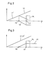
- the output signal U1 'of the sign stage 1 now bends downward, as can be seen from FIG. 2.
- the capacitor C2 gives the integration stage 2 a negative input signal, which appears at the output according to the following description.
- This signal is designated U2 and is shown in FIG. 2.
- the flip-flop 9 is switched over by the AND gate 8, so that a logical 1 is supplied to the associated input of the gate 7 and thus all three inputs of this gate 7 a logic 1 receive.
- switch S3 is now closed again and the voltage present at the output of integration stage 2 is a measure of the time difference between the arrival of the two signals FB and LS.
- This voltage is fed to the converter 3, which in this case, where the control deviation is negative, ensures that the conveying device of the extruder is brought to a lower conveying capacity.
- the preform should be ready at a point in time at which the blow mold is not yet ready to be closed again.
- the signal LS occurs before the signal FB. Until the arrival of the Signal LS this case corresponds to case 1 above.
- switch S3 is opened.
- the switch S1 Since, in contrast to case 1, the switch S1 remains closed until the signal FB arrives, the signal U1 'rises continuously, so that the voltage U2 at the output of the integration stage 2 assumes positive values, the final value of which in turn depends on the time between the arrival of the Signals LS and FB is determined. The end value is reached when the switch S3 is opened, which in turn is the case when the two signals FB and LS are present at the logic element 7 at the same time.
- the conveyor of the extruder When the control circuit is fully regulated, the conveyor of the extruder operates at a speed which causes the two signals LS and FB to occur simultaneously, which means that the preform reaches its desired length just when the blow mold is ready to close.
- the blow mold can therefore be operated at maximum speed and the conveyor of the extruder automatically adapts to the speed without any waiting times. Control deviations can, however, lead to the possibly undesirable result that the preform already reaches its desired length at a point in time when the blow mold is not yet ready again. If the ready signal FB of the blow mold is awaited in this case, the preform becomes too long by an amount corresponding to the control deviation. In order to take this case into account, the delay circuit 5 is provided.
- the control is set in such a way that the desired length of the preform is only achieved when the blow mold has already been "ready" for one second.
- the delay circuit 5 preferably contains a potentiometer with which the delay time can be set. Negative control deviations which are smaller than the size of the set time period To can therefore not lead to the preform becoming too long.
- the comparators K1 and K2 which compare the ramp signal U1 supplied to them on the input side with the extreme value signals, outside of which the regulation is to be overridden, provide no output signal, as a result of which the switch S4 is opened.
- the control deviation signal is therefore not supplied to the drive for the screw conveyor of the extruder.
- control deviation signal is also fed via line KS as a correction signal to the programmer of the extruder, in order to ensure that the program sequence for the wall thickness curve is based on the cycle time.
- the circuit described above is not limited to use with an extruder, but can be used wherever the occurrence of a first event is to be coordinated with that of a second event.
- the logic circuit specified here prevents the second event from occurring before or after the first event.
Applications Claiming Priority (2)
| Application Number | Priority Date | Filing Date | Title |
|---|---|---|---|
| DE2940904 | 1979-10-09 | ||
| DE19792940904 DE2940904A1 (de) | 1979-10-09 | 1979-10-09 | Verfahren und vorrichtung zum regeln der foerderleistung eines extruders |
Publications (4)
| Publication Number | Publication Date |
|---|---|
| EP0027575A2 true EP0027575A2 (fr) | 1981-04-29 |
| EP0027575A3 EP0027575A3 (en) | 1981-09-02 |
| EP0027575B1 EP0027575B1 (fr) | 1983-10-12 |
| EP0027575B2 EP0027575B2 (fr) | 1989-03-08 |
Family
ID=6083076
Family Applications (1)
| Application Number | Title | Priority Date | Filing Date |
|---|---|---|---|
| EP80105926A Expired EP0027575B2 (fr) | 1979-10-09 | 1980-09-30 | Dispositif pour régler la capacité de production d'une extrudeuse |
Country Status (3)
| Country | Link |
|---|---|
| EP (1) | EP0027575B2 (fr) |
| JP (1) | JPS5695651A (fr) |
| DE (2) | DE2940904A1 (fr) |
Cited By (2)
| Publication number | Priority date | Publication date | Assignee | Title |
|---|---|---|---|---|
| TR22308A (tr) * | 1983-09-30 | 1987-01-20 | Du Pont | Egirme pompasi malzeme verimini kontrol etmek icin yoentem |
| WO1991006418A1 (fr) * | 1989-11-01 | 1991-05-16 | Krupp Kautex Maschinenbau Gmbh | Procede de fabrication de pieces creuses en matiere thermoplastique |
Families Citing this family (1)
| Publication number | Priority date | Publication date | Assignee | Title |
|---|---|---|---|---|
| JP2833673B2 (ja) * | 1991-04-30 | 1998-12-09 | 宇部興産株式会社 | ブロー成形機の型締制御方法および装置 |
Citations (4)
| Publication number | Priority date | Publication date | Assignee | Title |
|---|---|---|---|---|
| DE1529787B1 (de) * | 1962-06-01 | 1971-05-13 | Battenfeld Geb | Einrichtung zur ueberwachung von programmgesteuerten spritz guss press oder blasautomaten zur verarbeitung von kunst stoffen |
| US3759648A (en) * | 1971-09-15 | 1973-09-18 | Hunker Instr Dev Labor Inc | Extruder control system |
| DE2544609B2 (de) * | 1975-10-06 | 1978-10-19 | Kautex Werke Reinold Hagen Gmbh, 5300 Bonn-Holzlar | Einrichtung zum Beeinflussen der Endlänge eines Vorformlings aus thermoplastischem Kunststoff |
| DE2558780B2 (de) * | 1975-12-24 | 1978-11-09 | Kautex Werke Reinold Hagen Gmbh, 5300 Bonn-Holzlar | Vorrichtung zum Herstellen von Hohlkörpern aus thermoplastischem Kunststoff im Extrusions-Blasverfahren |
Family Cites Families (3)
| Publication number | Priority date | Publication date | Assignee | Title |
|---|---|---|---|---|
| JPS5344921B2 (fr) * | 1973-07-19 | 1978-12-02 | ||
| DE2544171C3 (de) * | 1975-10-03 | 1978-10-26 | Kautex Werke Reinold Hagen Gmbh, 5300 Bonn-Holzlar | Vorrichtung zum Steuern der Bewegung der Blasform und der Teile derselben beim Herstellen von Hohlkörpern aus thermoplastischem Kunststoff |
| DE2813241C2 (de) * | 1978-03-28 | 1984-08-30 | Moog GmbH, 7030 Böblingen | Verfahren zum Regeln des Füllungsgrades eines Speichers in einer Fördereinrichtung eines Extruders und Vorrichtung zum Durchführen dieses Verfahrens |
-
1979
- 1979-10-09 DE DE19792940904 patent/DE2940904A1/de not_active Withdrawn
-
1980
- 1980-09-30 DE DE8080105926T patent/DE3065302D1/de not_active Expired
- 1980-09-30 EP EP80105926A patent/EP0027575B2/fr not_active Expired
- 1980-10-08 JP JP14110680A patent/JPS5695651A/ja active Granted
Patent Citations (4)
| Publication number | Priority date | Publication date | Assignee | Title |
|---|---|---|---|---|
| DE1529787B1 (de) * | 1962-06-01 | 1971-05-13 | Battenfeld Geb | Einrichtung zur ueberwachung von programmgesteuerten spritz guss press oder blasautomaten zur verarbeitung von kunst stoffen |
| US3759648A (en) * | 1971-09-15 | 1973-09-18 | Hunker Instr Dev Labor Inc | Extruder control system |
| DE2544609B2 (de) * | 1975-10-06 | 1978-10-19 | Kautex Werke Reinold Hagen Gmbh, 5300 Bonn-Holzlar | Einrichtung zum Beeinflussen der Endlänge eines Vorformlings aus thermoplastischem Kunststoff |
| DE2558780B2 (de) * | 1975-12-24 | 1978-11-09 | Kautex Werke Reinold Hagen Gmbh, 5300 Bonn-Holzlar | Vorrichtung zum Herstellen von Hohlkörpern aus thermoplastischem Kunststoff im Extrusions-Blasverfahren |
Cited By (3)
| Publication number | Priority date | Publication date | Assignee | Title |
|---|---|---|---|---|
| TR22308A (tr) * | 1983-09-30 | 1987-01-20 | Du Pont | Egirme pompasi malzeme verimini kontrol etmek icin yoentem |
| WO1991006418A1 (fr) * | 1989-11-01 | 1991-05-16 | Krupp Kautex Maschinenbau Gmbh | Procede de fabrication de pieces creuses en matiere thermoplastique |
| US5409647A (en) * | 1989-11-01 | 1995-04-25 | Krupp Kautex Maschinenbau Gmbh | Process for the production of hollow bodies from thermoplastic material |
Also Published As
| Publication number | Publication date |
|---|---|
| EP0027575A3 (en) | 1981-09-02 |
| EP0027575B1 (fr) | 1983-10-12 |
| DE3065302D1 (en) | 1983-11-17 |
| DE2940904A1 (de) | 1981-04-23 |
| JPS5695651A (en) | 1981-08-03 |
| JPS642500B2 (fr) | 1989-01-17 |
| EP0027575B2 (fr) | 1989-03-08 |
Similar Documents
| Publication | Publication Date | Title |
|---|---|---|
| EP0062788B1 (fr) | Procédé et dispositif pour la fabrication en particulier d'ébauches creuses en matière thermoplastique | |
| EP0026828B1 (fr) | Dispositif pour influencer le poids d'un corps creux thermoplastique fabriqué selon le procédé d'extrusion-soufflage | |
| DE2544609C3 (de) | Einrichtung zum Beeinflussen der Länge eines Vorformlings aus thermoplastischem Kunststoff | |
| DE3208502C2 (de) | Glasformmaschine | |
| EP0897786B1 (fr) | Procédé de régulation d'une machine de moulage par injection de matières plastiques | |
| DE2558780A1 (de) | Vorrichtung zum herstellen von hohlkoerpern aus thermoplastischem kunststoff im blasverfahren | |
| DE19801881C1 (de) | Verfahren zur Beurteilung von Spritzteilen | |
| EP0162045B1 (fr) | Procede de regulation de l'epaisseur de paroi de paraisons tubulaires | |
| DE60312107T2 (de) | Luftversorgungsvorrichtung für Düsenwebmaschine | |
| DE2542331A1 (de) | Strangpresse | |
| EP0027575A2 (fr) | Dispositif pour régler la capacité de production d'une extrudeuse | |
| EP0242824A2 (fr) | Procédé et dispositif pour le réglage d'au moins deux propriétés physiques déterminantes pour la qualité du produit fini d'un boudin à fumer | |
| DE3936301A1 (de) | Verfahren zum herstellen von hohlkoerpern aus thermoplastischen kunststoff | |
| DE19739827B4 (de) | Verfahren und Vorrichtung zur Steuerung einer Betriebsgröße eines Kraftfahrzeugs | |
| DE2544171C3 (de) | Vorrichtung zum Steuern der Bewegung der Blasform und der Teile derselben beim Herstellen von Hohlkörpern aus thermoplastischem Kunststoff | |
| AT522166A4 (de) | Verfahren und Kontrollvorrichtung zum Kontrollieren eines Fahrzeugs | |
| EP0407847B1 (fr) | Procédé et dispositif pour produire des corps creux en matière thermoplastique | |
| DE4421171C1 (de) | Verfahren zum Extrusionsblasformen von Hohlkörpern aus thermoplastischem Kunststoff | |
| DE3416781A1 (de) | Verfahren zum herstellen von vorformlingen aus thermoplastischem kunststoff fuer das blasformen von hohlkoerpern | |
| WO2021073997A1 (fr) | Procédé de surveillance d'au moins une partie d'un processus de production d'un système d'extrusion de film | |
| WO2020094652A1 (fr) | Dispositif d'inversion et procédé pour faire passer une machine de production de feuilles plates d'un produit de base à un produit secondaire | |
| DE3042755A1 (de) | Verfahren und vorrichtung zur bearbeitung von werkstuecken mit mehreren bearbeitungsstationen | |
| DE102018127670A1 (de) | Stellvorrichtung für eine Kontrolle einer Austrittsdicke eines Düsenaustrittsspaltes einer Flachfolienmaschine | |
| EP3711926B1 (fr) | Dispositif de soupape de soufflage pour un dispositif de soufflage | |
| DE1912107A1 (de) | Vorrichtung zur Positionsregelung |
Legal Events
| Date | Code | Title | Description |
|---|---|---|---|
| PUAI | Public reference made under article 153(3) epc to a published international application that has entered the european phase |
Free format text: ORIGINAL CODE: 0009012 |
|
| AK | Designated contracting states |
Designated state(s): BE CH DE FR GB |
|
| PUAL | Search report despatched |
Free format text: ORIGINAL CODE: 0009013 |
|
| AK | Designated contracting states |
Designated state(s): BE CH DE FR GB |
|
| 17P | Request for examination filed |
Effective date: 19811030 |
|
| GRAA | (expected) grant |
Free format text: ORIGINAL CODE: 0009210 |
|
| AK | Designated contracting states |
Designated state(s): BE CH DE FR GB LI |
|
| REF | Corresponds to: |
Ref document number: 3065302 Country of ref document: DE Date of ref document: 19831117 |
|
| ET | Fr: translation filed | ||
| PLBI | Opposition filed |
Free format text: ORIGINAL CODE: 0009260 |
|
| PLBI | Opposition filed |
Free format text: ORIGINAL CODE: 0009260 |
|
| 26 | Opposition filed |
Opponent name: KRUPP - KAUTEX GMBH Effective date: 19840703 |
|
| 26 | Opposition filed |
Opponent name: BATTENFELD-FISCHER BLASFORMTECHNIK GMBH Effective date: 19840712 Opponent name: BEKUM MASCHINENFABRIKEN GMBH Effective date: 19840710 |
|
| PGFP | Annual fee paid to national office [announced via postgrant information from national office to epo] |
Ref country code: BE Payment date: 19840930 Year of fee payment: 5 |
|
| RTI2 | Title (correction) |
Free format text: APPARATUS FOR CONTROLLING THE PRODUCTION RATE OF AN EXTRUDER. |
|
| PUAH | Patent maintained in amended form |
Free format text: ORIGINAL CODE: 0009272 |
|
| STAA | Information on the status of an ep patent application or granted ep patent |
Free format text: STATUS: PATENT MAINTAINED AS AMENDED |
|
| 27A | Patent maintained in amended form |
Effective date: 19890308 |
|
| AK | Designated contracting states |
Kind code of ref document: B2 Designated state(s): BE CH DE FR GB |
|
| ET3 | Fr: translation filed ** decision concerning opposition | ||
| PG25 | Lapsed in a contracting state [announced via postgrant information from national office to epo] |
Ref country code: BE Effective date: 19890930 |
|
| BERE | Be: lapsed |
Owner name: MOOG G.M.B.H. Effective date: 19890930 |
|
| PGFP | Annual fee paid to national office [announced via postgrant information from national office to epo] |
Ref country code: GB Payment date: 19910816 Year of fee payment: 12 |
|
| PGFP | Annual fee paid to national office [announced via postgrant information from national office to epo] |
Ref country code: FR Payment date: 19920916 Year of fee payment: 13 |
|
| PG25 | Lapsed in a contracting state [announced via postgrant information from national office to epo] |
Ref country code: GB Effective date: 19920930 |
|
| PGFP | Annual fee paid to national office [announced via postgrant information from national office to epo] |
Ref country code: CH Payment date: 19921111 Year of fee payment: 13 |
|
| GBPC | Gb: european patent ceased through non-payment of renewal fee |
Effective date: 19920930 |
|
| PG25 | Lapsed in a contracting state [announced via postgrant information from national office to epo] |
Ref country code: LI Effective date: 19930930 Ref country code: CH Effective date: 19930930 |
|
| PG25 | Lapsed in a contracting state [announced via postgrant information from national office to epo] |
Ref country code: FR Free format text: LAPSE BECAUSE OF NON-PAYMENT OF DUE FEES Effective date: 19940531 |
|
| REG | Reference to a national code |
Ref country code: CH Ref legal event code: PL |
|
| REG | Reference to a national code |
Ref country code: FR Ref legal event code: ST |
|
| PGFP | Annual fee paid to national office [announced via postgrant information from national office to epo] |
Ref country code: DE Payment date: 19961030 Year of fee payment: 17 |
|
| PG25 | Lapsed in a contracting state [announced via postgrant information from national office to epo] |
Ref country code: DE Free format text: LAPSE BECAUSE OF NON-PAYMENT OF DUE FEES Effective date: 19980603 |
|
| APAH | Appeal reference modified |
Free format text: ORIGINAL CODE: EPIDOSCREFNO |