EP0027575A2 - Apparatus for controlling the production rate of an extruder - Google Patents
Apparatus for controlling the production rate of an extruder Download PDFInfo
- Publication number
- EP0027575A2 EP0027575A2 EP80105926A EP80105926A EP0027575A2 EP 0027575 A2 EP0027575 A2 EP 0027575A2 EP 80105926 A EP80105926 A EP 80105926A EP 80105926 A EP80105926 A EP 80105926A EP 0027575 A2 EP0027575 A2 EP 0027575A2
- Authority
- EP
- European Patent Office
- Prior art keywords
- preform
- blow mold
- signal
- cycle time
- time
- Prior art date
- Legal status (The legal status is an assumption and is not a legal conclusion. Google has not performed a legal analysis and makes no representation as to the accuracy of the status listed.)
- Granted
Links
Images

Classifications
-
- B—PERFORMING OPERATIONS; TRANSPORTING
- B29—WORKING OF PLASTICS; WORKING OF SUBSTANCES IN A PLASTIC STATE IN GENERAL
- B29C—SHAPING OR JOINING OF PLASTICS; SHAPING OF MATERIAL IN A PLASTIC STATE, NOT OTHERWISE PROVIDED FOR; AFTER-TREATMENT OF THE SHAPED PRODUCTS, e.g. REPAIRING
- B29C49/00—Blow-moulding, i.e. blowing a preform or parison to a desired shape within a mould; Apparatus therefor
- B29C49/42—Component parts, details or accessories; Auxiliary operations
- B29C49/78—Measuring, controlling or regulating
-
- B—PERFORMING OPERATIONS; TRANSPORTING
- B29—WORKING OF PLASTICS; WORKING OF SUBSTANCES IN A PLASTIC STATE IN GENERAL
- B29C—SHAPING OR JOINING OF PLASTICS; SHAPING OF MATERIAL IN A PLASTIC STATE, NOT OTHERWISE PROVIDED FOR; AFTER-TREATMENT OF THE SHAPED PRODUCTS, e.g. REPAIRING
- B29C48/00—Extrusion moulding, i.e. expressing the moulding material through a die or nozzle which imparts the desired form; Apparatus therefor
- B29C48/25—Component parts, details or accessories; Auxiliary operations
- B29C48/92—Measuring, controlling or regulating
-
- B—PERFORMING OPERATIONS; TRANSPORTING
- B29—WORKING OF PLASTICS; WORKING OF SUBSTANCES IN A PLASTIC STATE IN GENERAL
- B29C—SHAPING OR JOINING OF PLASTICS; SHAPING OF MATERIAL IN A PLASTIC STATE, NOT OTHERWISE PROVIDED FOR; AFTER-TREATMENT OF THE SHAPED PRODUCTS, e.g. REPAIRING
- B29C49/00—Blow-moulding, i.e. blowing a preform or parison to a desired shape within a mould; Apparatus therefor
- B29C49/42—Component parts, details or accessories; Auxiliary operations
- B29C49/78—Measuring, controlling or regulating
- B29C2049/7873—Extrusion speed; Extruded preform position or length; Extrusion fall speed
-
- B—PERFORMING OPERATIONS; TRANSPORTING
- B29—WORKING OF PLASTICS; WORKING OF SUBSTANCES IN A PLASTIC STATE IN GENERAL
- B29C—SHAPING OR JOINING OF PLASTICS; SHAPING OF MATERIAL IN A PLASTIC STATE, NOT OTHERWISE PROVIDED FOR; AFTER-TREATMENT OF THE SHAPED PRODUCTS, e.g. REPAIRING
- B29C2948/00—Indexing scheme relating to extrusion moulding
- B29C2948/92—Measuring, controlling or regulating
- B29C2948/92009—Measured parameter
- B29C2948/92114—Dimensions
- B29C2948/92142—Length
-
- B—PERFORMING OPERATIONS; TRANSPORTING
- B29—WORKING OF PLASTICS; WORKING OF SUBSTANCES IN A PLASTIC STATE IN GENERAL
- B29C—SHAPING OR JOINING OF PLASTICS; SHAPING OF MATERIAL IN A PLASTIC STATE, NOT OTHERWISE PROVIDED FOR; AFTER-TREATMENT OF THE SHAPED PRODUCTS, e.g. REPAIRING
- B29C2948/00—Indexing scheme relating to extrusion moulding
- B29C2948/92—Measuring, controlling or regulating
- B29C2948/92504—Controlled parameter
- B29C2948/9258—Velocity
- B29C2948/926—Flow or feed rate
-
- B—PERFORMING OPERATIONS; TRANSPORTING
- B29—WORKING OF PLASTICS; WORKING OF SUBSTANCES IN A PLASTIC STATE IN GENERAL
- B29C—SHAPING OR JOINING OF PLASTICS; SHAPING OF MATERIAL IN A PLASTIC STATE, NOT OTHERWISE PROVIDED FOR; AFTER-TREATMENT OF THE SHAPED PRODUCTS, e.g. REPAIRING
- B29C2948/00—Indexing scheme relating to extrusion moulding
- B29C2948/92—Measuring, controlling or regulating
- B29C2948/92504—Controlled parameter
- B29C2948/92609—Dimensions
- B29C2948/92657—Volume or quantity
-
- B—PERFORMING OPERATIONS; TRANSPORTING
- B29—WORKING OF PLASTICS; WORKING OF SUBSTANCES IN A PLASTIC STATE IN GENERAL
- B29C—SHAPING OR JOINING OF PLASTICS; SHAPING OF MATERIAL IN A PLASTIC STATE, NOT OTHERWISE PROVIDED FOR; AFTER-TREATMENT OF THE SHAPED PRODUCTS, e.g. REPAIRING
- B29C2948/00—Indexing scheme relating to extrusion moulding
- B29C2948/92—Measuring, controlling or regulating
- B29C2948/92819—Location or phase of control
- B29C2948/92857—Extrusion unit
- B29C2948/92904—Die; Nozzle zone
-
- B—PERFORMING OPERATIONS; TRANSPORTING
- B29—WORKING OF PLASTICS; WORKING OF SUBSTANCES IN A PLASTIC STATE IN GENERAL
- B29C—SHAPING OR JOINING OF PLASTICS; SHAPING OF MATERIAL IN A PLASTIC STATE, NOT OTHERWISE PROVIDED FOR; AFTER-TREATMENT OF THE SHAPED PRODUCTS, e.g. REPAIRING
- B29C48/00—Extrusion moulding, i.e. expressing the moulding material through a die or nozzle which imparts the desired form; Apparatus therefor
- B29C48/03—Extrusion moulding, i.e. expressing the moulding material through a die or nozzle which imparts the desired form; Apparatus therefor characterised by the shape of the extruded material at extrusion
- B29C48/09—Articles with cross-sections having partially or fully enclosed cavities, e.g. pipes or channels
-
- B—PERFORMING OPERATIONS; TRANSPORTING
- B29—WORKING OF PLASTICS; WORKING OF SUBSTANCES IN A PLASTIC STATE IN GENERAL
- B29C—SHAPING OR JOINING OF PLASTICS; SHAPING OF MATERIAL IN A PLASTIC STATE, NOT OTHERWISE PROVIDED FOR; AFTER-TREATMENT OF THE SHAPED PRODUCTS, e.g. REPAIRING
- B29C49/00—Blow-moulding, i.e. blowing a preform or parison to a desired shape within a mould; Apparatus therefor
- B29C49/02—Combined blow-moulding and manufacture of the preform or the parison
- B29C49/04—Extrusion blow-moulding
Definitions
- the invention relates to a method according to the preamble of claim 1 and an apparatus for performing this method.
- thermoplastic material is extruded continuously or in batches from an extrusion head.
- the extruded preform will then expanded in a blow mold onto the hollow body to be produced.
- the two-part or multi-part blow mold is subjected to a working cycle, at the cycle time of which the speed at which the preform is extruded must be adapted.
- a regulation is known with which it can be achieved that the blow mold is not closed before the desired length of the preform is reached.
- this regulation makes it necessary to plan in each cycle a waiting time between the time when the blow mold is ready to close and the target time in which the preform is to have reached its target length.
- the present invention has for its object to provide a method and an apparatus that are easy to use and do not require mold waiting times.
- a regulation is achieved which leads to the preform reaching its desired length at exactly the point in time at which the blow mold is ready for the closing process.
- This regulation is based on the fact that the time differences between the occurrence of the shape-ready signal and the signal that indicates that the preform has reached its target length is made zero.
- a logic circuit is provided which causes the mold to be closed only when the preform has actually reached its desired length has reached. This means that mold waiting times can be completely eliminated.
- a preferred further development is specified in claim 2. This ensures that small control deviations are not taken into account and changes in the delivery rate are not carried out with every work cycle.
- the measure specified in claim 3 has the effect that the deviation not to be taken into account is automatically adapted to different cycle times. Without the measure according to claim 4, the following disadvantage could occur. If, for example, the delivery rate decreases at a certain point in time, the machine cycle becomes longer because the blow mold only closes when the preform reaches its desired length. The program execution time of the wall thickness programmer for the next cycle adjusts to this now longer cycle time. If the extruder speed is then increased due to the excessive mold waiting times, the preform will reach its desired length earlier than in the previous cycle due to the higher delivery capacity of the extruder.
- the desired value of the control which is normally determined by the cycle time with which the blow mold works, can be increased by a predetermined period of time. This makes it easy to avoid, even in the event of a control deviation, that the preform has been extruded beyond the desired length by the time the blow mold is ready again. In addition, this measure makes it easy to plan a "mold waiting time" just in case it should be necessary.
- a preferred method variant is specified in claim 6. It takes into account the case that the light barrier or a corresponding other sensor for the respective length of the preform cannot be arranged where the end of the preform is when it has reached its desired length. This problem exists, for example, in the case of blowing and / or expanding mandrels. In this case, the light barrier is mounted correspondingly higher.
- the circuit shown in FIG. 1 contains only that part of the control which relates to the generation of the control deviation signal.
- the remaining parts belonging to the complete extruder and its control are conventional and are not described in detail here. Except for the special features described in the present application, the regulation can be carried out in the manner described in German patent application P 28 04 145.4.
- the circuit shown essentially consists of a derailleur circuit of a sign stage 1, a switch S2, a differentiation stage consisting of a capacitor C2, an integration stage 2, a switch S4, a converter 3 and the logic circuit 4 serving to control these circuit parts.
- the sign stage 1 consists of an operational amplifier A1, the inverting input terminal of which is connected via a resistor R1 and the non-inverting input of which is connected via a switch S1 to an input terminal of this sign stage 1, to which a voltage U1 is supplied.
- the non-inverting input of operational amplifier A1 is grounded via a capacitor C1.
- the inverting input is connected via a resistor R2 to the output terminal of the operational amplifier A1, to which a voltage 1 'is applied.
- the integration stage consists of a further operational amplifier A2, to which both a capacitor C3 and a switch S3 are connected in parallel.
- the converter 3 is connected to the output of the integration stage 2 via the switch S4.
- a line KS is connected to the input connection of the converter 3, which line is connected to the programmer of the extruder and supplies a correction signal for the programmer, as will be described further below.
- the logic circuit 4 connected to the circuit section described above is provided with three input connections, to which signals FB (form ready), LS (light barrier), ST (start signal) and U1 (ramp signal) are supplied.
- the signal FB is submit from the blow mold give if it can be closed for the blow molding process.
- the signal LS comes from a light barrier and occurs when the preform has reached its target length.
- the signal U1 represents the ramp signal which is also fed to the sign stage 1 on the input side.
- the input connections of the logic circuit 4 carrying these signals are given the same designations as the signals themselves.
- the switches S1, S2, S3 and S4 are each provided with actuators BS1, BS2, BS3 and BS4, which convert these switches to their closed state when a "logical 1" is supplied to them on the input side.
- the FB connection is connected to a delay circuit 5, the. Function explained below.
- the output of the delay circuit 5 is connected to the actuator BF1 via an inverter 6. Furthermore, the output of the delay circuit 5 is connected to the one of three inputs of a logic element 7 and the one of two inputs of a UMD logic element 8.
- the LS input is connected to the other input of the AND logic element 8 and the second input of the logic element 7 connected.
- the output of the AND gate 8 is connected to the SET input of a flip-flop 9, the RESET input of which is connected to the ST input via a resistor R4.
- the Q output of flip-flop 9 is connected to the third input of logic element 7 and its Q output to actuator BS2.
- the output of the link 7 is at the actuator BF3.
- the input of the actuator BS4 is at the output of an AND gate with three inputs, the first of which is connected to the ST input via a capacitor C4 and the other two inputs of which are each connected to the output of a comparator K1 and K2.
- the ramping becomes one input of the comparators K1 and K2 Signal U1 supplied, while the other two remaining inputs receive voltages that are a predetermined value, for example 15% above or below the target end value of the ramp signal. With a target final value of 10V, these voltages are 11.5V and 8.5V.
- the lines FB and LS are connected to an AND gate 8a whose output is connected to a line BL which leads to the blow mold and which gives the start signal for closing.
- the two signals FB and LS indicate that both the mold is ready for the closing process and that the preform has reached its desired length.
- These signals are fed to the AND logic element 8, which only emits a signal at the output if both conditions are met, so that it is ensured that the mold is only closed when it is ready and the preform is at its desired length has reached.
- This signal is fed via line BL to the blow mold, which initiates the closing process of this mold.
- the circuit shown in the drawing is intended to switch off dead times, which can occur due to the fact that the preform reaches its desired length only considerably later than the blow mold is ready for the closing process.
- the actuator for the mold could be designed so that it only responds to an actuation signal when it is ready for the new cycle.
- the FB signal appears before the LS signal.
- the signal ST is generated, which resets the flip-flop 9.
- the switch S2 is closed via the actuator BS2.
- the case that one of the two comparators K1 and K2 does not emit an output signal is for the time being disregarded. Since the signal FB is not yet present, the switch S1 is also closed via the inverter 6 and the actuator BS1.
- the ramp signal U1 which is used in conventional extruders to control the programmer as a function of time, is fed to the input of the sign stage 1.
- the voltage U1 1 at the output of the sign stage 1 has the same profile as the ramp signal U1 until the signal FB arrives.
- switch S3 is closed, integration stage 2 generates no output signal.
- This switch S3 is on the actuation link BS3 closed by the link 7 and only when the three signals fed to the link 7 on the input side all have either a logic 0 or a logic 1. This condition is met before the arrival of the two signals FB and LS, since the flip-flop 9 also does not deliver an output signal at the U output. If the FB signal arrives, switches S1 and S3 are opened at the same time.
- the output signal U1 'of the sign stage 1 now bends downward, as can be seen from FIG. 2.
- the capacitor C2 gives the integration stage 2 a negative input signal, which appears at the output according to the following description.
- This signal is designated U2 and is shown in FIG. 2.
- the flip-flop 9 is switched over by the AND gate 8, so that a logical 1 is supplied to the associated input of the gate 7 and thus all three inputs of this gate 7 a logic 1 receive.
- switch S3 is now closed again and the voltage present at the output of integration stage 2 is a measure of the time difference between the arrival of the two signals FB and LS.
- This voltage is fed to the converter 3, which in this case, where the control deviation is negative, ensures that the conveying device of the extruder is brought to a lower conveying capacity.
- the preform should be ready at a point in time at which the blow mold is not yet ready to be closed again.
- the signal LS occurs before the signal FB. Until the arrival of the Signal LS this case corresponds to case 1 above.
- switch S3 is opened.
- the switch S1 Since, in contrast to case 1, the switch S1 remains closed until the signal FB arrives, the signal U1 'rises continuously, so that the voltage U2 at the output of the integration stage 2 assumes positive values, the final value of which in turn depends on the time between the arrival of the Signals LS and FB is determined. The end value is reached when the switch S3 is opened, which in turn is the case when the two signals FB and LS are present at the logic element 7 at the same time.
- the conveyor of the extruder When the control circuit is fully regulated, the conveyor of the extruder operates at a speed which causes the two signals LS and FB to occur simultaneously, which means that the preform reaches its desired length just when the blow mold is ready to close.
- the blow mold can therefore be operated at maximum speed and the conveyor of the extruder automatically adapts to the speed without any waiting times. Control deviations can, however, lead to the possibly undesirable result that the preform already reaches its desired length at a point in time when the blow mold is not yet ready again. If the ready signal FB of the blow mold is awaited in this case, the preform becomes too long by an amount corresponding to the control deviation. In order to take this case into account, the delay circuit 5 is provided.
- the control is set in such a way that the desired length of the preform is only achieved when the blow mold has already been "ready" for one second.
- the delay circuit 5 preferably contains a potentiometer with which the delay time can be set. Negative control deviations which are smaller than the size of the set time period To can therefore not lead to the preform becoming too long.
- the comparators K1 and K2 which compare the ramp signal U1 supplied to them on the input side with the extreme value signals, outside of which the regulation is to be overridden, provide no output signal, as a result of which the switch S4 is opened.
- the control deviation signal is therefore not supplied to the drive for the screw conveyor of the extruder.
- control deviation signal is also fed via line KS as a correction signal to the programmer of the extruder, in order to ensure that the program sequence for the wall thickness curve is based on the cycle time.
- the circuit described above is not limited to use with an extruder, but can be used wherever the occurrence of a first event is to be coordinated with that of a second event.
- the logic circuit specified here prevents the second event from occurring before or after the first event.
Abstract
Description
Die Erfindung bezieht sich auf ein Verfahren nach dem Oberbegriff des Anspruchs 1 und eine Vorrichtung zum Durchführen dieses Verfahrens.The invention relates to a method according to the preamble of
Bei bekannten Extrudern wird das thermoplastische Material aus einem Strangpreßkopf kontinuierlich oder schubweise extrudiert. Der extrudierte Vorformling wird anschließend in einer Blasform auf den herzustellenden Hohlkörper aufgeweitet. Die zwei- oder mehrteilige Blasform ist dabei einem Arbeitszyklus unterworfen, an dessen Zykluszeit die Geschwindigkeit, mit der der Vorformling extrudiert wird, angepaßt werden muß. Aus der DE-PS 25 44 171 ist eine Regelung bekannt, mit der erreicht werden kann, daß die Blasform nicht geschlossen wird, bevor die Soll-Länge des Vorformlings erreicht ist. Diese Regelung macht es aber erforderlich, in jedem Zyklus eine Wartezeit zwischen dem Zeitpunkt, in dem die Blasform zum Schließen bereit ist und der Soll-Zeit, in der der Vorformling seine Soll-Länge erreicht haben soll, einzuplanen. In dem in dieser Patentschrift dargestellten Ausführungsbeispiel sind drei Zeitpunkte TO (Zeitpunkt an dem die Blasform bereit ist), T1 und T2 (Zeitpunkte zwischen denen die Soll-Länge des Vorformlings erreicht werden soll) aufeinanderabzustimmen, wobei die letztgenannten Zeitpunkte getrennt einzustellen sind. Unsachgemäße Einstellungen führen zu fehlerhaften Produkten. Insbesondere ist aber die einzukalkulierende Formwartezeit aus Produktivitätsgründen unerwünscht.In known extruders, the thermoplastic material is extruded continuously or in batches from an extrusion head. The extruded preform will then expanded in a blow mold onto the hollow body to be produced. The two-part or multi-part blow mold is subjected to a working cycle, at the cycle time of which the speed at which the preform is extruded must be adapted. From DE-PS 25 44 171 a regulation is known with which it can be achieved that the blow mold is not closed before the desired length of the preform is reached. However, this regulation makes it necessary to plan in each cycle a waiting time between the time when the blow mold is ready to close and the target time in which the preform is to have reached its target length. In the exemplary embodiment shown in this patent specification, three times TO (time at which the blow mold is ready), T1 and T2 (times between which the desired length of the preform is to be reached) are to be coordinated, the latter times having to be set separately. Improper settings lead to defective products. In particular, the form waiting time to be calculated is undesirable for reasons of productivity.
Der vorliegenden Erfindung liegt die Aufgabe zugrunde, ein Verfahren und eine Vorrichtung anzugeben, die einfach zu handhaben sind und keine Formwartezeiten erforderlich machen.The present invention has for its object to provide a method and an apparatus that are easy to use and do not require mold waiting times.
Diese Aufgabe wird mit den kennzeichnenden Merkmalen der Ansprüche 1 und 8 gelöst.This object is achieved with the characterizing features of
Bei dem angegebenen Verfahren wird eine Regelung erreicht, die dazu führt, daß der Vorformling genau zu dem Zeitpunkt seine Soll-Länge erreicht, in dem die Blasform für den Schließvorgang bereit ist. Diese Regelung beruht darauf, daß die Zeitdifferenzen zwischen dem Auftreten des Formbereitschaftssignals und dem Signal,das angibt, daß der Vorformling seine Soll-Länge erreicht hat, zu Null gemacht wird. Um zu verhindern, daß die Form bereits zu einem Zeitpunkt geschlossen wird, an den der Vorformling noch nicht seine Soll-Länge erreicht hat, ist eine Verknüpfungsschaltung vorgesehen, die bewirkt, daß die Form erst geschlossen wird, wenn der Vorformling tatsächlich seine Soll-Länge erreicht hat. Damit können Formwartezeiten vollständig eliminiert werden.In the method specified, a regulation is achieved which leads to the preform reaching its desired length at exactly the point in time at which the blow mold is ready for the closing process. This regulation is based on the fact that the time differences between the occurrence of the shape-ready signal and the signal that indicates that the preform has reached its target length is made zero. In order to prevent the mold from being closed at a point in time at which the preform has not yet reached its desired length, a logic circuit is provided which causes the mold to be closed only when the preform has actually reached its desired length has reached. This means that mold waiting times can be completely eliminated.
Eine bevorzugte Weiterbildung ist im Anspruch 2 angegeben. Dadurch wird erreicht, daß geringe Regelabweichungen unberücksichtigt bleiben und Änderungen der Förderleistung nicht bei jedem Arbeitszyklus durchgeführt werden. Durch die im Anspruch 3 angegebene Maßnahme wird bewirkt, daß die nicht zu berücksichtigende Abweichung selbsttätig an unterschiedliche Zykluszeiten angepaßt wird. Ohne die Maßnahme nach Anspruch 4 könnte folgender Nachteil auftreten. Nimmt beispielsweise die Förderleistung zu einem bestimmten Zeitpunkt ab, so wird der Maschinenzyklus länger, da die Blasform erst dann schließt, wenn der Vorformling seine Soll-Länge erreicht. Auf diese jetzt längere Zykluszeit stellt sich die Programmablaufzeit des Wanddicken-Programmierers für den nächsten Zyklus ein. Wird dann aufgrund der zu großen Formwrartezeiten die Extruderdrehzahl erhöht, wird infolge der höheren Förderleistung des Extruders der Vorformling seine Soll-Länge früher als im vorigen Zyklus erreichen. Die Form wird dann früher schließen, wodurch sich der Maschinenzyklus kürzt. Da die Programmablaufzeit gemäß dem vorigen längeren Zyklus eingestellt ist, wird sich die Lage des Vorformlingprofils relativ zur Form ändern. Die Lage wird sich insbesondere bei den letzten Programmpunkten ändern, da der Programmablauf des Wanddickenprogrammierers früher als vorgesehen abgebrochen wird. Bei größeren Korrekturen der Extruderdrehzahl kann es sogar vorkommen, daß die letzten Punkte des Wanddickenprogrammierers gar nicht mehr abgefragt werden. Die Veränderungen der Lage des Vorformlings relativ zur Form beeinträchtigt aber die Artikelqualität erheblich und kann sogar zu Ausschußproduktion führen. Mit der im Anspruch 4 angegebenen Maßnahme wird dieser Nachteil behoben.A preferred further development is specified in
Durch die im Anspruch 5 angegebene Maßnahme läßt sich der Soll-Wert der Regelung, der normalerweise durch die Zykluszeit, mit der die Blasform arbeitet, bestimmt ist, um eine vorgegebene Zeitspanne erhöhen. Damit läßt sich auf einfache Weise auch bei auftretender Regelabweichung vermeiden, daß der Vorformling bis zu dem Zeitpunkt, an dem die Blasform wieder bereit ist, über die Soll-Länge hinaus extrudiert wurde. Außerdem kann durch diese Maßnahme eine "Formwartezeit" für den Fall leicht eingeplant werden, wenn sie einmal erforderlich sein sollte.By means of the measure specified in
Eine bevorzugte Verfahrensvariante ist im Anspruch 6 angegeben. Sie trägt dem Fall Rechnung, daß die Lichtschranke oder ein entsprechender anderer Sensor für die jeweilige Länge des Vorformlings nicht dort angeordnet werden kann, wo sich das Ende des Vorformlings befindet, wenn er seine Soll-Länge erreicht hat. Dieses Problem gibt es beispielsweise bei Blas- und/oder Spreizdornen. Die Lichtschranke wird in diesem Fall entsprechend höher montiert.A preferred method variant is specified in
Die Merkmale des Anspruchs 7 führen zu dem Vorteil, daß größere Abweichungen, die beispielsweise bei einer Maschinenstörung oder beim Maschinenanlauf auftreten, zu keiner unnötigen Regelung führen, die beispielsweise das Einstellen der Maschine beim Anlaufen erschweren könnten.The features of
Vorteilhafte Ausführungsformen sind in den Vorrichtungsansprüchen angegeben. Als besonderer Vorteil wird es bei diesen Ausführungsformen angesehen, daß das ohnehin bei solchen Extrudern vorhandene Rampensignal zum Feststellen der Regelabweichung ausgenutzt wird. Die darauf aufgebauten elektrischen Schaltungen werden dabei sehr einfach.Advantageous embodiments are specified in the device claims. It is regarded as a particular advantage in these embodiments that the ramp signal, which is present in any case with such extruders, is used to determine the control deviation. The electrical circuits built on it become very simple.
Anhand eines in der Zeichnung dargestellten Ausführungsbeispiels wird die Erfindung im folgenden näher erläutert. Es zeigen:
- Fig. 1 ein Schaltbeispiel des Teils der erfindungsgemäßen Regelung, der sich auf die Erzeugung des Regelsignals bezieht;
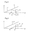
- Fig. 2 ein Zeitdiagramm für in dem Schaltbeispiel nach Fig. i auftretende Spannungsverläufe für den Fall, daß die Blasform bereits bereit ist, während der Vorformling noch nicht ganz extrudiert ist, und
- Fig. 3 ein Zeitdiagramm entsprechend demjenigen nach Fig. 2, für den Fall, daß der Vorformling bereits fertig ist, bevor die Blasform betätigt werden kann.
- Figure 1 is a circuit example of the part of the control according to the invention, which relates to the generation of the control signal.
- FIG. 2 shows a time diagram for voltage curves occurring in the circuit example according to FIG. I in the event that the blow mold is already ready while the preform is not yet completely extruded, and
- Fig. 3 is a timing diagram corresponding to that of FIG. 2, in the event that the preform is already finished before the blow mold can be operated.
Die in Fig. 1 dargestellte Schaltung enthält nur denjenigen Teil der Regelung, der sich auf die Erzeugung des Regelabweichsignals bezieht. Die zum vollständigen Extruder und seiner Steuerung gehörenden übrigen Teile sind herkömmlicher Art und hier nicht näher beschrieben. Bis auf die in der vorliegenden Anmeldung beschriebenen 'Besonderheiten kann die Regelung in der Art ausgeführt sein, wie sie in der deutschen Patentanmeldung P 28 04 145.4 beschrieben ist.The circuit shown in FIG. 1 contains only that part of the control which relates to the generation of the control deviation signal. The remaining parts belonging to the complete extruder and its control are conventional and are not described in detail here. Except for the special features described in the present application, the regulation can be carried out in the manner described in German patent application P 28 04 145.4.
Die dargestellte Schaltung besteht im wesentlichen aus der Kettenschaltung einer Vorzeichenstufe 1, eines Schalters S2, einer aus einem Kondensator C2 bestehenden Differenzierstufe, einer Integrationsstufe 2, einem Schalter S4, einem Umsetzer 3 und der zur Steuerung dieser Schaltungsteile dienenden logischen Schaltung 4.The circuit shown essentially consists of a derailleur circuit of a
Die Vorzeichenstufe 1 besteht aus einem Operationsverstärker A1, dessen invertierender Eingangsanschluß über einen Widerstand R1 und dessen nicht-invertierender Eingang über einen Schalter S1 mit einem Eingangsanschluß dieser Vorzeichenstufe 1 verbunden ist, dem eine Spannung U1 zugeführt wird. Der nicht-invertierende Eingang des Operationsverstärkers A1 ist über einen Kondensator C1 geerdet. Der invertierende Eingang ist über einen Widerstand R2 mit dem Ausgangsanschluß des Operationsverstärkers A1 verbunden, an dem eine Spannung 1' anliegt. Die Integrationsstufe besteht aus einem weiteren Operationsverstärker A2, dem sowohl ein Kondensator C3, als ein Schalter S3 parallel geschaltet sind. Der Umsetzer 3 ist über den Schalter S4 mit dem Ausgang der Integrationsstufe 2 verbunden. Er liefert ausgangsseitig das Regelabweichsignal für die Geschwindigkeitsregelung der Fördereinrichtung des Extruders, die beispielsweise als Motor für einen Schneckenantrieb ausgebildet ist, der dem Strangpreßkopf das zu extrudierende Material zuführt. An den Eingangsanschluß des Umsetzers 3 ist-eine Leitung KS angeschlossen, die mit dem Programmierer des Extruders verbunden ist und ein Korrektursignal für den Programmierer liefert, wie es weiter unten noch beschrieben wird.The
Die an den oben beschriebenen Schaltungsteil angeschlossene logische Schaltung 4 ist mit drei Eingangsanschlüssen versehen, denen Signale FB (Form bereit), LS (Lichtschranke), ST (Startsignal) und U1 (Rampensignal) zugeführt werden. Das Signal FB wird von der Blasform abgegeben, wenn sie für den Blasformvorgang geschlossen werden kann. Das Signal LS stammt von einer Lichtschranke und tritt dann auf, wenn der Vorformling seine Soll-Länge erreicht hat. Das Signal U1 stellt das Rampensignal dar, das auch der Vorzeichenstufe 1 eingangsseitig zugeführt wird. Der besseren Verständlichkeit wegen werden die diese Signale führenden Eingangsanschlüsse der logischen Schaltung 4 mit denselben Bezeichnungen wie die Signale selbst versehen.The logic circuit 4 connected to the circuit section described above is provided with three input connections, to which signals FB (form ready), LS (light barrier), ST (start signal) and U1 (ramp signal) are supplied. The signal FB is abge from the blow mold give if it can be closed for the blow molding process. The signal LS comes from a light barrier and occurs when the preform has reached its target length. The signal U1 represents the ramp signal which is also fed to the
Die Schalter S1, S2, S3 und S4 sind jeweils mit Betätigungsgliedern BS1, BS2, BS3 und BS4 versehen, die diese Schalter jeweils dann in ihren geschlossenen Zustand überführen, wenn ihnen eingangsseitig eine "logische 1" zugeführt wird. Der FB-Anschluß ist mit einer Verzögerungsschaltung 5 verbunden, deren. Funktion weiter unten erläutert wird. Der Ausgang der Verzögerungsschaltung 5 ist über einen Inverter 6 mit dem Betätigungsglied BF1 verbunden. Weiterhin ist der Ausgang der Verzögerungsschaltung 5 verbunden mit dem einen von drei Eingängen eines Verknüpfungsglieds 7 und dem einen von zwei Eingängen eines UMD-Verknüpfungsglieds 8. Der LS-Eingang ist mit dem anderen Eingang des UND-Verknüpfungsglieds 8 und dem zweiten Eingang des Verknüpfungsglieds 7 verbunden. Der Ausgang des UND-Verknüpfungsglieds 8 ist angeschlossen an den SET-Eingang eines Flip-Flops 9, dessen RESET-Eingang über einen Widerstand R4 am ST-Eingang liegt. Der Q-Ausgang des Flip-Flops 9 ist mit dem dritten Eingang des Verknüpfungsglieds 7 verbunden und sein Q-Ausgang mit dem Betätigungsglied BS2. Der Ausgang des Verknüpfungsglieds 7 liegt am Betätigungsglied BF3. Der Eingang des Betätigungsglieds BS4 liegt am Ausgang eines UND-Verknüpfungsglieds mit drei Eingängen, deren erster über einen Kondensator C4 mit dem ST-Eingang verbunden ist und deren beide andere Eingänge jeweils mit dem Ausgang eines Komparators K1 und K2 verbunden sind. Jeweils einem Eingang der Komparatoren K1 und K2 wird das Rampensignal U1 zugeführt, während die beiden anderen verbleibenden Eingänge Spannungen erhalten, die einen vorgegebenen Wert von beispielsweise 15% über oder unter dem Soll-Endwert des Rampensignals liegen. Bei einem Soll-Endwert von 10V liegen diese Spannungen bei 11,5 V und 8,5V. Die Leitungen FB und LS sind an ein UND-Verknüpfungsglied 8a angeschlossen dessen Ausgang mit einer Leitung BL verbunden ist, die zur Blasform führt und dieser das Startsignal zum Schließen gibt.The switches S1, S2, S3 and S4 are each provided with actuators BS1, BS2, BS3 and BS4, which convert these switches to their closed state when a "logical 1" is supplied to them on the input side. The FB connection is connected to a
Im folgenden wird die Wirkungsweise der oben im Aufbau beschriebenen Schaltung erläutert. Die beiden Signale FB und LS geben bei ihrem Auftreten an, daß sowohl die Form für den Schließvorgang bereit ist, als auch, daß der Vorformling seine Soll-Länge erreicht hat. Diese Signale werden dem UND-Verknüpfungsglied 8 zugeführt, das am Ausgang nur dann ein Signal abgibt, wenn beide Bedingungen erfüllt sind, so daß sichergestellt ist, daß die Form nur dann geschlossen wird, wenn sie selbst bereit ist und der Vorformling seine Soll-Länge erreicht hat. Dieses Signal wird über die Leitung BL der Blasform zugeführt, die den Schließvorgang dieser Form einleitet. Die in der Zeichnung dargestellte Schaltung soll Totzeiten, die dadurch auftreten können, daß der Vorformling seine Soll-Länge erst vesentlich später erreicht, als die Blasform für den.Schließvorgang bereit ist, ausschalten. Solche Totzeiten hat man bei bekannten Schaltungen (siehe Patentanmeldung P 25 44 171) absichtlich eingebaut, um sicherzustellen, daß die Blasform nicht bereits geschlossen wird, bevor die Soll-Länge des Vorformlings erreicht ist. Die in der Zeichnung dargestellte Schaltung erzeugt ein Regelausgangssignal am Umsetzer 3, das proportional ist der Zeitdifferenz zwischen dem Auftreten der Signale LS und FB. Dieses Regelabweichsignal wird benutzt, um die Fördereinrichtung des Extruders nachzustellen, so daß im Idealfall der Vorformling gerade dann seine Soll-Länge erreicht hat, wenn die Blasform für den Schließvorgang bereit ist. Bei dieser Regelung bildet die Zykluszeit, mit der die Blasform arbeitet, den Sollwert, auf den sich die Zykluszeit, in der der Vorformling seine Soll-Länge erreichen soll, einstellt. Da es bei einer solchen Regelung vorkommen kann, daß der Ist-Wert den Sollwert unterschreitet, was hier bedeuten würde, daß der Vorformling seine Soll-Länge erreicht bevor die Form wieder bereit ist. Um die Form aber nur dann zu schließen, wenn sie auch bereit ist, ist eine Logikschaltung vorgesehen, die diesem Fall Rechnung trägt. Es könnte stattdessen auch die Betätigungsvorrichtung für die Form so ausgebildet sein, daß sie auf ein Betätigungssignal erst anspricht, wenn sie für den neuen Zyklus bereit ist.The mode of operation of the circuit described above in the construction is explained below. When they occur, the two signals FB and LS indicate that both the mold is ready for the closing process and that the preform has reached its desired length. These signals are fed to the AND logic element 8, which only emits a signal at the output if both conditions are met, so that it is ensured that the mold is only closed when it is ready and the preform is at its desired length has reached. This signal is fed via line BL to the blow mold, which initiates the closing process of this mold. The circuit shown in the drawing is intended to switch off dead times, which can occur due to the fact that the preform reaches its desired length only considerably later than the blow mold is ready for the closing process. Such dead times have been intentionally installed in known circuits (see patent application P 25 44 171) to ensure that the blow mold is not closed before the desired length of the preform is reached. The circuit shown in the drawing generates a control output signal at the
Betrachten wir zunächst den ersten Fall, daß die Blasform bereits für den Schließvorgang bereit ist, bevor der Vorformling seine Soll-Länge erreicht hat. In diesem Fall erscheint das Signal FB vor dem Signal LS. Zu Beginn des Arbeitszyklus wird das Signal ST erzeugt, das das Flip-Flop 9 rücksetzt. Dadurch wird über das Betätigungsglied BS2 der Schalter S2 geschlossen. Der Fall, daß einer der beiden Komparatoren K1 und K2 kein Ausgangssignal abgibt, sei vorläufig noch außer Betracht gelassen. Da das Signal FB noch nicht ansteht, wird über den Inverter 6 und das Betätigungsglied BS1 auch der Schalter S1 geschlossen. Dem Eingang der Vorzeichenstufe 1 wird das Rampensignal U1 zugeführt, das in üblichen Extrudern dazu verwendet wird, den Programmierer zeitabhängig zu steuern. Die Spannung U11 am Ausgang der Vorzeichenstufe 1 hat bis zum Eintreffen des Signals FB denselben Verlauf wie das Rampensignal U1. Solange der Schalter S3 geschlossen ist, erzeugt die Integrationsstufe 2 kein Ausgangssignal. Dieser Schalter S3 wird über das Betätigungsglied BS3 durch das Verknüpfungsglied 7 dann und nur dann geschlossen, wenn die dem Verknüpfungsglied 7 eingangsseitig zugeführten drei Signale alle entweder eine logische 0 oder eine logische 1 haben. Vor dem Eintreffen der beiden Signale FB und LS ist diese Bedingung erfüllt, da auch das Flip-Flop 9 kein Ausgangssignal am U-Ausgang liefert. Trifft nun das Signal FB ein, werden gleichzeitig die Schalter S1 und S3 geöffnet. Das Ausgangssignal U1' der Vorzeichenstufe 1 knickt nun nach unten um, wie dies aus Fig. 2 ersichtlich ist. Durch den Kondensator C2 erhält die Integrationsstufe 2 ein negatives Eingangssignal, das am Ausgang gemäß folgender Bezeichnung erscheint.
Im zweiten Fall, der in einem Zeitdiagramm in Fig. 3 dargestellt ist, soll der Vorformling bereits zu einem Zeitpunkt fertig sein, in dem die Blasform noch nicht wieder zum Schließen bereit ist. In diesem Fall tritt das Signal LS vor dem Signal FB auf. Bis zum Eintreffen des Signals LS entspricht dieser Fall dem obigen Fall 1. Bei Eintreffen des Signals LS wird der Schalter S3 geöffnet.In the second case, which is shown in a time diagram in FIG. 3, the preform should be ready at a point in time at which the blow mold is not yet ready to be closed again. In this case, the signal LS occurs before the signal FB. Until the arrival of the Signal LS this case corresponds to
Da im Gegensatz zum Fall 1 bis zum Eintreffen des Signals FB der Schalter S1 geschlossen bleibt, steigt das Signal U1' kontinuierlich an, so daß die Spannung U2 am Ausgang der Integrationsstufe 2 positive Werte annimmt, deren Endwert wiederum von der Zeitdauer zwischen dem Eintreffen der Signale LS und FB bestimmt wird. Der Endwert wird erreicht, wenn der Schalter S3 geöffnet wird, was wiederum dann der Fall ist, wenn die beiden Signale FB und LS gleichzeitig am Verknüpfungsglied 7 anliegen.Since, in contrast to
Bei vollständig ausgeregeltem Regelkreis arbeitet die Fördereinrichtung des Extruders mit einer Geschwindigkeit, die dazu führt, daß die beiden Signale LS und FB gleichzeitig auftreten, was bedeutet, daß der Vorformling seine Soll-Länge gerade dann erreicht, wenn die Blasform zum Schließen bereit ist. Man kann die Blasform deshalb mit maximaler Geschwindigkeit arbeiten lassen und die Fördereinrichtung des Extruders paßt sich automatisch an die Geschwindigkeit ohne Auftreten irgendwelcher Wartezeiten an. Regelabweichungen können allerdings zu dem unter Umständen unerwünschten Ergebnis führen, daß der Vorformling seine Soll-Länge bereits zu einem Zeitpunkt erreicht, in dem die Blasform noch nicht wieder bereit ist. Wird in diesem Fall das Bereitschaftssignal FB der Blasform abgewartet, wird der Vorformling um eine der Regelabweichung entsprechende Größe zu lang. Um diesem Fall Rechnung zu tragen, ist der Verzögerungskreis 5 vorgesehen. Stellt man diesen Verzögerungskreis 5 beispielsweise auf eine Sekunde, stellt sich die Regelung so ein, daß die Soll-Länge des Vorformlings erst dann erreicht wird, wenn die Blasform bereits eine Sekunde auf "Bereitschaft" stand. Der Verzögerungskreis 5 enthält vorzugsweise ein Potentiometer, mit dem die Verzögerungszeit einstellbar ist. Negative Regelabweichungen, die kleiner als die Größe der eingestellten Zeitspanne To sind können deshalb nicht dazu führen, daß der Vorformling zu lang wird.When the control circuit is fully regulated, the conveyor of the extruder operates at a speed which causes the two signals LS and FB to occur simultaneously, which means that the preform reaches its desired length just when the blow mold is ready to close. The blow mold can therefore be operated at maximum speed and the conveyor of the extruder automatically adapts to the speed without any waiting times. Control deviations can, however, lead to the possibly undesirable result that the preform already reaches its desired length at a point in time when the blow mold is not yet ready again. If the ready signal FB of the blow mold is awaited in this case, the preform becomes too long by an amount corresponding to the control deviation. In order to take this case into account, the
Für manche Betriebsfälle erscheint es sinnvoll, die Regelung außer Kraft zu setzen, beispielsweise bei einer Maschinenstörung. In diesem Fall liefern die Komparatoren K1 und K2, die das ihnen eingangsseitig zugeführte Rampensignal U1 mit den Extremwertsignalen vergleichen, außerhalb denen die Regelung außer Kraft gesetzt werden soll, kein Ausgangssignal, wodurch der Schalter S4 geöffnet wird. Das Regelabweichsignal wird deshalb dem Antrieb für die Förderschnecke des Extruders nicht zugeführt.For some operating cases, it makes sense to override the control, for example in the event of a machine malfunction. In this case, the comparators K1 and K2, which compare the ramp signal U1 supplied to them on the input side with the extreme value signals, outside of which the regulation is to be overridden, provide no output signal, as a result of which the switch S4 is opened. The control deviation signal is therefore not supplied to the drive for the screw conveyor of the extruder.
Das Regelabweichsignal wird über die Leitung KS als Korrektursignal auch dem Programmgeber des Extruders zugeleitet, um sicherzustellen, daß der Programmablauf für den Wandstärkenverlauf auf die Zykluszeit abgestellt wird.The control deviation signal is also fed via line KS as a correction signal to the programmer of the extruder, in order to ensure that the program sequence for the wall thickness curve is based on the cycle time.
Die oben beschriebene Schaltung ist nicht auf die Verwendung bei einem Extruder beschränkt, sondern kann überall dort eingesetzt werden, wo das zeitliche Eintreten eines ersten Ereignisses mit demjenigen eines zweiten Ereignisses koordiniert werden soll.The circuit described above is not limited to use with an extruder, but can be used wherever the occurrence of a first event is to be coordinated with that of a second event.
Die hier angegebene Logikschaltung verhindert, daß das zweite Ereignis vor oder nach dem ersten Ereignis auftritt.The logic circuit specified here prevents the second event from occurring before or after the first event.
Claims (12)

Applications Claiming Priority (2)
| Application Number | Priority Date | Filing Date | Title |
|---|---|---|---|
| DE19792940904 DE2940904A1 (en) | 1979-10-09 | 1979-10-09 | METHOD AND DEVICE FOR REGULATING THE PROCESSING PERFORMANCE OF AN EXTRUDER |
| DE2940904 | 1979-10-09 |
Publications (4)
| Publication Number | Publication Date |
|---|---|
| EP0027575A2 true EP0027575A2 (en) | 1981-04-29 |
| EP0027575A3 EP0027575A3 (en) | 1981-09-02 |
| EP0027575B1 EP0027575B1 (en) | 1983-10-12 |
| EP0027575B2 EP0027575B2 (en) | 1989-03-08 |
Family
ID=6083076
Family Applications (1)
| Application Number | Title | Priority Date | Filing Date |
|---|---|---|---|
| EP80105926A Expired EP0027575B2 (en) | 1979-10-09 | 1980-09-30 | Apparatus for controlling the production rate of an extruder |
Country Status (3)
| Country | Link |
|---|---|
| EP (1) | EP0027575B2 (en) |
| JP (1) | JPS5695651A (en) |
| DE (2) | DE2940904A1 (en) |
Cited By (2)
| Publication number | Priority date | Publication date | Assignee | Title |
|---|---|---|---|---|
| TR22308A (en) * | 1983-09-30 | 1987-01-20 | Du Pont | YOENTEM TO CHECK THE SPINNING PUMP MATERIAL EFFICIENCY |
| WO1991006418A1 (en) * | 1989-11-01 | 1991-05-16 | Krupp Kautex Maschinenbau Gmbh | Process for the production of hollow bodies from thermoplastic material |
Families Citing this family (1)
| Publication number | Priority date | Publication date | Assignee | Title |
|---|---|---|---|---|
| JP2833673B2 (en) * | 1991-04-30 | 1998-12-09 | 宇部興産株式会社 | Mold clamping control method and apparatus for blow molding machine |
Citations (4)
| Publication number | Priority date | Publication date | Assignee | Title |
|---|---|---|---|---|
| DE1529787B1 (en) * | 1962-06-01 | 1971-05-13 | Battenfeld Geb | DEVICE FOR MONITORING PROGRAM-CONTROLLED INJECTION, CASTING, PRESSING OR BLOWING MACHINES FOR THE PROCESSING OF PLASTICS |
| US3759648A (en) * | 1971-09-15 | 1973-09-18 | Hunker Instr Dev Labor Inc | Extruder control system |
| DE2544609B2 (en) * | 1975-10-06 | 1978-10-19 | Kautex Werke Reinold Hagen Gmbh, 5300 Bonn-Holzlar | Device for influencing the final length of a preform made of thermoplastic material |
| DE2558780B2 (en) * | 1975-12-24 | 1978-11-09 | Kautex Werke Reinold Hagen Gmbh, 5300 Bonn-Holzlar | Device for the production of hollow bodies from thermoplastic material in the extrusion blow molding process |
Family Cites Families (3)
| Publication number | Priority date | Publication date | Assignee | Title |
|---|---|---|---|---|
| JPS5344921B2 (en) * | 1973-07-19 | 1978-12-02 | ||
| DE2544171C3 (en) * | 1975-10-03 | 1978-10-26 | Kautex Werke Reinold Hagen Gmbh, 5300 Bonn-Holzlar | Device for controlling the movement of the blow mold and the parts thereof when producing hollow bodies from thermoplastic material |
| DE2813241C2 (en) * | 1978-03-28 | 1984-08-30 | Moog GmbH, 7030 Böblingen | Method for regulating the degree of filling of a store in a conveying device of an extruder and device for carrying out this method |
-
1979
- 1979-10-09 DE DE19792940904 patent/DE2940904A1/en not_active Withdrawn
-
1980
- 1980-09-30 EP EP80105926A patent/EP0027575B2/en not_active Expired
- 1980-09-30 DE DE8080105926T patent/DE3065302D1/en not_active Expired
- 1980-10-08 JP JP14110680A patent/JPS5695651A/en active Granted
Patent Citations (4)
| Publication number | Priority date | Publication date | Assignee | Title |
|---|---|---|---|---|
| DE1529787B1 (en) * | 1962-06-01 | 1971-05-13 | Battenfeld Geb | DEVICE FOR MONITORING PROGRAM-CONTROLLED INJECTION, CASTING, PRESSING OR BLOWING MACHINES FOR THE PROCESSING OF PLASTICS |
| US3759648A (en) * | 1971-09-15 | 1973-09-18 | Hunker Instr Dev Labor Inc | Extruder control system |
| DE2544609B2 (en) * | 1975-10-06 | 1978-10-19 | Kautex Werke Reinold Hagen Gmbh, 5300 Bonn-Holzlar | Device for influencing the final length of a preform made of thermoplastic material |
| DE2558780B2 (en) * | 1975-12-24 | 1978-11-09 | Kautex Werke Reinold Hagen Gmbh, 5300 Bonn-Holzlar | Device for the production of hollow bodies from thermoplastic material in the extrusion blow molding process |
Cited By (3)
| Publication number | Priority date | Publication date | Assignee | Title |
|---|---|---|---|---|
| TR22308A (en) * | 1983-09-30 | 1987-01-20 | Du Pont | YOENTEM TO CHECK THE SPINNING PUMP MATERIAL EFFICIENCY |
| WO1991006418A1 (en) * | 1989-11-01 | 1991-05-16 | Krupp Kautex Maschinenbau Gmbh | Process for the production of hollow bodies from thermoplastic material |
| US5409647A (en) * | 1989-11-01 | 1995-04-25 | Krupp Kautex Maschinenbau Gmbh | Process for the production of hollow bodies from thermoplastic material |
Also Published As
| Publication number | Publication date |
|---|---|
| EP0027575A3 (en) | 1981-09-02 |
| DE2940904A1 (en) | 1981-04-23 |
| EP0027575B2 (en) | 1989-03-08 |
| DE3065302D1 (en) | 1983-11-17 |
| JPS5695651A (en) | 1981-08-03 |
| JPS642500B2 (en) | 1989-01-17 |
| EP0027575B1 (en) | 1983-10-12 |
Similar Documents
| Publication | Publication Date | Title |
|---|---|---|
| EP0062788B1 (en) | Method and apparatus for producing preferably hollow parisons of a thermoplast | |
| EP0026828B1 (en) | Device for influencing the weight of a hollow thermoplastic body produced by the extrusion-blowing method | |
| DE2544609C3 (en) | Device for influencing the length of a preform made of thermoplastic material | |
| DE3208502C2 (en) | Glass forming machine | |
| EP0897786B1 (en) | Regulation process for an injection moulding machine for plastics | |
| EP0909628A2 (en) | Method and apparatus to regulate heating of a hot runner in a multicavity mould | |
| EP0058297A1 (en) | Method of and apparatus for producing a thermoplastic parison by an extruder | |
| DE2558780A1 (en) | DEVICE FOR THE PRODUCTION OF HOLLOW BODIES FROM THERMOPLASTIC PLASTIC IN THE BLOW PROCESS | |
| DE19801881C1 (en) | Assessment of molding quality achieved by pressure injection molding machine | |
| EP0162045B1 (en) | Method for regulating the wall thickness of tubular preforms | |
| DE60312107T2 (en) | Air supply device for jet loom | |
| DE2542331A1 (en) | EXTRUSION PRESS | |
| EP0027575A2 (en) | Apparatus for controlling the production rate of an extruder | |
| EP0242824A2 (en) | Method and device for the regulation of at least two determinant physical characteristics for the quality of the finished product of a smoking rod | |
| DE3936301A1 (en) | METHOD FOR PRODUCING HOLLOW BODIES FROM THERMOPLASTIC PLASTIC | |
| DE2544171C3 (en) | Device for controlling the movement of the blow mold and the parts thereof when producing hollow bodies from thermoplastic material | |
| AT522166A4 (en) | Method and control device for controlling a vehicle | |
| EP0407847B1 (en) | Method and apparatus for manufacturing hollow thermoplastic bodies | |
| DE4421171C1 (en) | Process for extrusion blow molding of hollow bodies made of thermoplastic | |
| EP4045982A1 (en) | Monitoring method for monitoring at least one part of a production process of a film extrusion system | |
| DE3416781A1 (en) | Process for producing parisons from a thermoplastic for blow moulding hollow bodies | |
| WO2020094652A1 (en) | Switching device and method for switching a flat film machine from an input product to a subsequent product | |
| DE3042755A1 (en) | Step=by=step workpiece machining system - carries out measurement after each step and uses results to control next step | |
| DE102018127670A1 (en) | Actuating device for checking an exit thickness of a nozzle exit gap of a flat film machine | |
| EP3711926B1 (en) | Blow valve device of a blowing device |
Legal Events
| Date | Code | Title | Description |
|---|---|---|---|
| PUAI | Public reference made under article 153(3) epc to a published international application that has entered the european phase |
Free format text: ORIGINAL CODE: 0009012 |
|
| AK | Designated contracting states |
Designated state(s): BE CH DE FR GB |
|
| PUAL | Search report despatched |
Free format text: ORIGINAL CODE: 0009013 |
|
| AK | Designated contracting states |
Designated state(s): BE CH DE FR GB |
|
| 17P | Request for examination filed |
Effective date: 19811030 |
|
| GRAA | (expected) grant |
Free format text: ORIGINAL CODE: 0009210 |
|
| AK | Designated contracting states |
Designated state(s): BE CH DE FR GB LI |
|
| REF | Corresponds to: |
Ref document number: 3065302 Country of ref document: DE Date of ref document: 19831117 |
|
| ET | Fr: translation filed | ||
| PLBI | Opposition filed |
Free format text: ORIGINAL CODE: 0009260 |
|
| PLBI | Opposition filed |
Free format text: ORIGINAL CODE: 0009260 |
|
| 26 | Opposition filed |
Opponent name: KRUPP - KAUTEX GMBH Effective date: 19840703 |
|
| 26 | Opposition filed |
Opponent name: BATTENFELD-FISCHER BLASFORMTECHNIK GMBH Effective date: 19840712 Opponent name: BEKUM MASCHINENFABRIKEN GMBH Effective date: 19840710 |
|
| PGFP | Annual fee paid to national office [announced via postgrant information from national office to epo] |
Ref country code: BE Payment date: 19840930 Year of fee payment: 5 |
|
| RTI2 | Title (correction) |
Free format text: APPARATUS FOR CONTROLLING THE PRODUCTION RATE OF AN EXTRUDER. |
|
| PUAH | Patent maintained in amended form |
Free format text: ORIGINAL CODE: 0009272 |
|
| STAA | Information on the status of an ep patent application or granted ep patent |
Free format text: STATUS: PATENT MAINTAINED AS AMENDED |
|
| 27A | Patent maintained in amended form |
Effective date: 19890308 |
|
| AK | Designated contracting states |
Kind code of ref document: B2 Designated state(s): BE CH DE FR GB |
|
| ET3 | Fr: translation filed ** decision concerning opposition | ||
| PG25 | Lapsed in a contracting state [announced via postgrant information from national office to epo] |
Ref country code: BE Effective date: 19890930 |
|
| BERE | Be: lapsed |
Owner name: MOOG G.M.B.H. Effective date: 19890930 |
|
| PGFP | Annual fee paid to national office [announced via postgrant information from national office to epo] |
Ref country code: GB Payment date: 19910816 Year of fee payment: 12 |
|
| PGFP | Annual fee paid to national office [announced via postgrant information from national office to epo] |
Ref country code: FR Payment date: 19920916 Year of fee payment: 13 |
|
| PG25 | Lapsed in a contracting state [announced via postgrant information from national office to epo] |
Ref country code: GB Effective date: 19920930 |
|
| PGFP | Annual fee paid to national office [announced via postgrant information from national office to epo] |
Ref country code: CH Payment date: 19921111 Year of fee payment: 13 |
|
| GBPC | Gb: european patent ceased through non-payment of renewal fee |
Effective date: 19920930 |
|
| PG25 | Lapsed in a contracting state [announced via postgrant information from national office to epo] |
Ref country code: LI Effective date: 19930930 Ref country code: CH Effective date: 19930930 |
|
| PG25 | Lapsed in a contracting state [announced via postgrant information from national office to epo] |
Ref country code: FR Free format text: LAPSE BECAUSE OF NON-PAYMENT OF DUE FEES Effective date: 19940531 |
|
| REG | Reference to a national code |
Ref country code: CH Ref legal event code: PL |
|
| REG | Reference to a national code |
Ref country code: FR Ref legal event code: ST |
|
| PGFP | Annual fee paid to national office [announced via postgrant information from national office to epo] |
Ref country code: DE Payment date: 19961030 Year of fee payment: 17 |
|
| PG25 | Lapsed in a contracting state [announced via postgrant information from national office to epo] |
Ref country code: DE Free format text: LAPSE BECAUSE OF NON-PAYMENT OF DUE FEES Effective date: 19980603 |
|
| APAH | Appeal reference modified |
Free format text: ORIGINAL CODE: EPIDOSCREFNO |