EP0162045B1 - Method for regulating the wall thickness of tubular preforms - Google Patents
Method for regulating the wall thickness of tubular preforms Download PDFInfo
- Publication number
- EP0162045B1 EP0162045B1 EP84900506A EP84900506A EP0162045B1 EP 0162045 B1 EP0162045 B1 EP 0162045B1 EP 84900506 A EP84900506 A EP 84900506A EP 84900506 A EP84900506 A EP 84900506A EP 0162045 B1 EP0162045 B1 EP 0162045B1
- Authority
- EP
- European Patent Office
- Prior art keywords
- wall thickness
- preform
- program
- points
- point
- Prior art date
- Legal status (The legal status is an assumption and is not a legal conclusion. Google has not performed a legal analysis and makes no representation as to the accuracy of the status listed.)
- Expired
Links
Images


Classifications
-
- B—PERFORMING OPERATIONS; TRANSPORTING
- B29—WORKING OF PLASTICS; WORKING OF SUBSTANCES IN A PLASTIC STATE IN GENERAL
- B29C—SHAPING OR JOINING OF PLASTICS; SHAPING OF MATERIAL IN A PLASTIC STATE, NOT OTHERWISE PROVIDED FOR; AFTER-TREATMENT OF THE SHAPED PRODUCTS, e.g. REPAIRING
- B29C49/00—Blow-moulding, i.e. blowing a preform or parison to a desired shape within a mould; Apparatus therefor
- B29C49/42—Component parts, details or accessories; Auxiliary operations
- B29C49/78—Measuring, controlling or regulating
-
- B—PERFORMING OPERATIONS; TRANSPORTING
- B29—WORKING OF PLASTICS; WORKING OF SUBSTANCES IN A PLASTIC STATE IN GENERAL
- B29C—SHAPING OR JOINING OF PLASTICS; SHAPING OF MATERIAL IN A PLASTIC STATE, NOT OTHERWISE PROVIDED FOR; AFTER-TREATMENT OF THE SHAPED PRODUCTS, e.g. REPAIRING
- B29C49/00—Blow-moulding, i.e. blowing a preform or parison to a desired shape within a mould; Apparatus therefor
- B29C49/02—Combined blow-moulding and manufacture of the preform or the parison
- B29C49/04—Extrusion blow-moulding
- B29C49/0411—Means for defining the wall or layer thickness
-
- B—PERFORMING OPERATIONS; TRANSPORTING
- B29—WORKING OF PLASTICS; WORKING OF SUBSTANCES IN A PLASTIC STATE IN GENERAL
- B29C—SHAPING OR JOINING OF PLASTICS; SHAPING OF MATERIAL IN A PLASTIC STATE, NOT OTHERWISE PROVIDED FOR; AFTER-TREATMENT OF THE SHAPED PRODUCTS, e.g. REPAIRING
- B29C48/00—Extrusion moulding, i.e. expressing the moulding material through a die or nozzle which imparts the desired form; Apparatus therefor
- B29C48/25—Component parts, details or accessories; Auxiliary operations
- B29C48/92—Measuring, controlling or regulating
-
- B—PERFORMING OPERATIONS; TRANSPORTING
- B29—WORKING OF PLASTICS; WORKING OF SUBSTANCES IN A PLASTIC STATE IN GENERAL
- B29C—SHAPING OR JOINING OF PLASTICS; SHAPING OF MATERIAL IN A PLASTIC STATE, NOT OTHERWISE PROVIDED FOR; AFTER-TREATMENT OF THE SHAPED PRODUCTS, e.g. REPAIRING
- B29C49/00—Blow-moulding, i.e. blowing a preform or parison to a desired shape within a mould; Apparatus therefor
- B29C49/02—Combined blow-moulding and manufacture of the preform or the parison
- B29C49/04—Extrusion blow-moulding
-
- B—PERFORMING OPERATIONS; TRANSPORTING
- B29—WORKING OF PLASTICS; WORKING OF SUBSTANCES IN A PLASTIC STATE IN GENERAL
- B29C—SHAPING OR JOINING OF PLASTICS; SHAPING OF MATERIAL IN A PLASTIC STATE, NOT OTHERWISE PROVIDED FOR; AFTER-TREATMENT OF THE SHAPED PRODUCTS, e.g. REPAIRING
- B29C2948/00—Indexing scheme relating to extrusion moulding
- B29C2948/92—Measuring, controlling or regulating
- B29C2948/92009—Measured parameter
- B29C2948/92114—Dimensions
- B29C2948/92142—Length
-
- B—PERFORMING OPERATIONS; TRANSPORTING
- B29—WORKING OF PLASTICS; WORKING OF SUBSTANCES IN A PLASTIC STATE IN GENERAL
- B29C—SHAPING OR JOINING OF PLASTICS; SHAPING OF MATERIAL IN A PLASTIC STATE, NOT OTHERWISE PROVIDED FOR; AFTER-TREATMENT OF THE SHAPED PRODUCTS, e.g. REPAIRING
- B29C2948/00—Indexing scheme relating to extrusion moulding
- B29C2948/92—Measuring, controlling or regulating
- B29C2948/92323—Location or phase of measurement
- B29C2948/92428—Calibration, after-treatment, or cooling zone
-
- B—PERFORMING OPERATIONS; TRANSPORTING
- B29—WORKING OF PLASTICS; WORKING OF SUBSTANCES IN A PLASTIC STATE IN GENERAL
- B29C—SHAPING OR JOINING OF PLASTICS; SHAPING OF MATERIAL IN A PLASTIC STATE, NOT OTHERWISE PROVIDED FOR; AFTER-TREATMENT OF THE SHAPED PRODUCTS, e.g. REPAIRING
- B29C2948/00—Indexing scheme relating to extrusion moulding
- B29C2948/92—Measuring, controlling or regulating
- B29C2948/92504—Controlled parameter
- B29C2948/92514—Pressure
-
- B—PERFORMING OPERATIONS; TRANSPORTING
- B29—WORKING OF PLASTICS; WORKING OF SUBSTANCES IN A PLASTIC STATE IN GENERAL
- B29C—SHAPING OR JOINING OF PLASTICS; SHAPING OF MATERIAL IN A PLASTIC STATE, NOT OTHERWISE PROVIDED FOR; AFTER-TREATMENT OF THE SHAPED PRODUCTS, e.g. REPAIRING
- B29C2948/00—Indexing scheme relating to extrusion moulding
- B29C2948/92—Measuring, controlling or regulating
- B29C2948/92504—Controlled parameter
- B29C2948/9258—Velocity
- B29C2948/9259—Angular velocity
-
- B—PERFORMING OPERATIONS; TRANSPORTING
- B29—WORKING OF PLASTICS; WORKING OF SUBSTANCES IN A PLASTIC STATE IN GENERAL
- B29C—SHAPING OR JOINING OF PLASTICS; SHAPING OF MATERIAL IN A PLASTIC STATE, NOT OTHERWISE PROVIDED FOR; AFTER-TREATMENT OF THE SHAPED PRODUCTS, e.g. REPAIRING
- B29C2948/00—Indexing scheme relating to extrusion moulding
- B29C2948/92—Measuring, controlling or regulating
- B29C2948/92504—Controlled parameter
- B29C2948/9258—Velocity
- B29C2948/926—Flow or feed rate
-
- B—PERFORMING OPERATIONS; TRANSPORTING
- B29—WORKING OF PLASTICS; WORKING OF SUBSTANCES IN A PLASTIC STATE IN GENERAL
- B29C—SHAPING OR JOINING OF PLASTICS; SHAPING OF MATERIAL IN A PLASTIC STATE, NOT OTHERWISE PROVIDED FOR; AFTER-TREATMENT OF THE SHAPED PRODUCTS, e.g. REPAIRING
- B29C2948/00—Indexing scheme relating to extrusion moulding
- B29C2948/92—Measuring, controlling or regulating
- B29C2948/92504—Controlled parameter
- B29C2948/92609—Dimensions
- B29C2948/92638—Length
-
- B—PERFORMING OPERATIONS; TRANSPORTING
- B29—WORKING OF PLASTICS; WORKING OF SUBSTANCES IN A PLASTIC STATE IN GENERAL
- B29C—SHAPING OR JOINING OF PLASTICS; SHAPING OF MATERIAL IN A PLASTIC STATE, NOT OTHERWISE PROVIDED FOR; AFTER-TREATMENT OF THE SHAPED PRODUCTS, e.g. REPAIRING
- B29C2948/00—Indexing scheme relating to extrusion moulding
- B29C2948/92—Measuring, controlling or regulating
- B29C2948/92504—Controlled parameter
- B29C2948/92609—Dimensions
- B29C2948/92647—Thickness
-
- B—PERFORMING OPERATIONS; TRANSPORTING
- B29—WORKING OF PLASTICS; WORKING OF SUBSTANCES IN A PLASTIC STATE IN GENERAL
- B29C—SHAPING OR JOINING OF PLASTICS; SHAPING OF MATERIAL IN A PLASTIC STATE, NOT OTHERWISE PROVIDED FOR; AFTER-TREATMENT OF THE SHAPED PRODUCTS, e.g. REPAIRING
- B29C2948/00—Indexing scheme relating to extrusion moulding
- B29C2948/92—Measuring, controlling or regulating
- B29C2948/92819—Location or phase of control
- B29C2948/92857—Extrusion unit
- B29C2948/92904—Die; Nozzle zone
-
- B—PERFORMING OPERATIONS; TRANSPORTING
- B29—WORKING OF PLASTICS; WORKING OF SUBSTANCES IN A PLASTIC STATE IN GENERAL
- B29C—SHAPING OR JOINING OF PLASTICS; SHAPING OF MATERIAL IN A PLASTIC STATE, NOT OTHERWISE PROVIDED FOR; AFTER-TREATMENT OF THE SHAPED PRODUCTS, e.g. REPAIRING
- B29C2948/00—Indexing scheme relating to extrusion moulding
- B29C2948/92—Measuring, controlling or regulating
- B29C2948/92819—Location or phase of control
- B29C2948/92923—Calibration, after-treatment or cooling zone
-
- B—PERFORMING OPERATIONS; TRANSPORTING
- B29—WORKING OF PLASTICS; WORKING OF SUBSTANCES IN A PLASTIC STATE IN GENERAL
- B29C—SHAPING OR JOINING OF PLASTICS; SHAPING OF MATERIAL IN A PLASTIC STATE, NOT OTHERWISE PROVIDED FOR; AFTER-TREATMENT OF THE SHAPED PRODUCTS, e.g. REPAIRING
- B29C2948/00—Indexing scheme relating to extrusion moulding
- B29C2948/92—Measuring, controlling or regulating
- B29C2948/92819—Location or phase of control
- B29C2948/92961—Auxiliary unit, e.g. for external melt filtering, re-combining or transfer between units
-
- B—PERFORMING OPERATIONS; TRANSPORTING
- B29—WORKING OF PLASTICS; WORKING OF SUBSTANCES IN A PLASTIC STATE IN GENERAL
- B29C—SHAPING OR JOINING OF PLASTICS; SHAPING OF MATERIAL IN A PLASTIC STATE, NOT OTHERWISE PROVIDED FOR; AFTER-TREATMENT OF THE SHAPED PRODUCTS, e.g. REPAIRING
- B29C2948/00—Indexing scheme relating to extrusion moulding
- B29C2948/92—Measuring, controlling or regulating
- B29C2948/92819—Location or phase of control
- B29C2948/9298—Start-up, shut-down or parameter setting phase; Emergency shut-down; Material change; Test or laboratory equipment or studies
-
- B—PERFORMING OPERATIONS; TRANSPORTING
- B29—WORKING OF PLASTICS; WORKING OF SUBSTANCES IN A PLASTIC STATE IN GENERAL
- B29C—SHAPING OR JOINING OF PLASTICS; SHAPING OF MATERIAL IN A PLASTIC STATE, NOT OTHERWISE PROVIDED FOR; AFTER-TREATMENT OF THE SHAPED PRODUCTS, e.g. REPAIRING
- B29C48/00—Extrusion moulding, i.e. expressing the moulding material through a die or nozzle which imparts the desired form; Apparatus therefor
- B29C48/03—Extrusion moulding, i.e. expressing the moulding material through a die or nozzle which imparts the desired form; Apparatus therefor characterised by the shape of the extruded material at extrusion
- B29C48/09—Articles with cross-sections having partially or fully enclosed cavities, e.g. pipes or channels
-
- B—PERFORMING OPERATIONS; TRANSPORTING
- B29—WORKING OF PLASTICS; WORKING OF SUBSTANCES IN A PLASTIC STATE IN GENERAL
- B29C—SHAPING OR JOINING OF PLASTICS; SHAPING OF MATERIAL IN A PLASTIC STATE, NOT OTHERWISE PROVIDED FOR; AFTER-TREATMENT OF THE SHAPED PRODUCTS, e.g. REPAIRING
- B29C49/00—Blow-moulding, i.e. blowing a preform or parison to a desired shape within a mould; Apparatus therefor
- B29C49/02—Combined blow-moulding and manufacture of the preform or the parison
- B29C49/04—Extrusion blow-moulding
- B29C49/041—Extrusion blow-moulding using an accumulator head
Definitions
- the invention relates to a method for regulating the wall thickness of hollow-stranded preforms made of thermoplastic material according to a predetermined program, the position of the preforms relative to the blow mold being checked by a measuring sensor, preferably a photocell, and then the preforms in a blow mold by internal pressure can be expanded to form a hollow body.
- the reason for the deviations of the preform length from the nominal value are the changes in the raw material properties, the mixing ratio of new material and regrind, additions to colors and other admixtures, changes in the melt temperature, the screw speed, etc. It is of little use if today's control devices have the preform length at a certain point Detect, form a signal to influence the screw speed or the basic gap, etc. from the time from a start pulse to reaching the measuring position.
- thermoplastic Different viscosities and temperatures of the thermoplastic lead to different elongation and different swelling behavior of the preform and each property to a different extent. The result is a shift in the position of the wall thickness points of the preform to the desired position in the finished hollow body or to the desired position in the blow mold.
- the invention has for its object to provide a method by which a constant quality of the hollow body to be produced and at the same time a saving in thermoplastic material is achieved.
- the object is achieved in that at least one predetermined cross-sectional area, preferably a critical area, of the respective preform is provided with one or more markings and / or the wall thickness of this cross-sectional area is measured, and that the position of the preform relative to the blow mold is dependent on the measurement of the markings by the transducer or by the wall thickness measurement, regardless of the total length of the preform, is regulated in such a way that the cross-sectional area mentioned comes to the correct position in the blow mold after the expansion.
- a predetermined cross-sectional area preferably a critical area
- the invention is based on the knowledge that it is essential in the production of hollow bodies that the parts of the preform, which are provided in particular for the critical areas of the hollow body according to the program, actually go to the right place within the hollow body or to get the right place of the blow mold.
- canisters can still be produced with a much lower operating weight of thermoplastic material if the compression value can be kept approximately constant.
- the switch radius and the base radius with its transitions on the canister are primarily responsible for a high compression value.
- a symmetry half is shown schematically over a program according to which the wall thicknesses of the preform are determined.
- the wall thickness of the preform results from the ramp, the safety gap, the basic gap and the set wall thickness program.
- the set program selection is 50% of the curve of the 100% program selection shown above.
- the critical point in the canister contour lies at a point KP1 in the shoulder of the canister.
- the largest wall thickness in the preform is also provided for this point under reference number 18 according to the program. Since the plastic is stretched out according to stretching lines, such as those shown in the drawing, it is essential that the plastic reaches the point KP1 in the canister from the wall thickness point 18.
- the position of each preform relative to the blow mold is controlled as a function of at least one predetermined cross-sectional area of the preform, in the present case according to the wall thickness point 18, that is to say preferably a critical area.
- a transducer e.g. B. provide a photocell FZ KP1 at a distance below the feed point of the preform, with the distance P1-18.
- the length of the preform is compared with the specified program in a wall thickness programmer and the proportion of the preform still to be ejected is dimensioned or changed so that the cross-sectional area, in the present case , after wall thickness point 18, in the right position for the blow mold or in the right place in the canister at KP1.
- a wall thickness point KP2 of the program can also be selected, which lies between the wall thickness points 8 and 9, so that it is accordingly ensured that the plastic material reaches the position KP2 of the canister contour exactly according to the points of the program.
- a sensor, for. B. a photocell FZKp2 can be arranged at a distance P1-8.5.
- the two position controls can also be combined with one another, with priority given to the most critical point or area in terms of control.
- the operating weight of the canister can be changed from 420 g to 340 g, for example, during the continuous production of the preforms. It is also assumed that the photocell FZkp1 is already set up.
- the operating weight is determined by the ratio between the basic gap GrSp, program selection PrW and, if necessary, the ramp Ra. To change the operating weight, there is a new ratio of basic gap, program selection and, if necessary, ramp.
- the program curve shown in FIG. 1 with a 100% program selection shows in the solid line a curve which, in the prior art, can only be produced over a long period of time with a lot of effort.
- the dashed curve shows the same use of material, but significantly higher mechanical values, i. H. that a significantly lower weight is required with the same mechanical values. It is advisable to keep the position of the extremely stuck curve constant even with respect to the blow mold.
- hose length controls are known, for example from DE-OS 29 40 904, with a light barrier, predominantly a photo cell, which is arranged as far as possible at the end of the preform, to regulate the preform length as constant as possible.
- control does not take place from any cross-section, but preferably from a control point, in the example described from the control point KP1.
- control is made only from one control point or cross-section, to mount the photocell as far as possible at the end of the preform in order to keep the preform length as constant as possible.
- the photocell at the control point KP1 would have to be available to determine the position. The position of the wall thickness points cannot be determined even with a hose length control. To date, there is neither a control nor a control concept for precise position control to compensate for the unavoidable disturbance variables.
- the portion of the preform still to be ejected is therefore determined by comparing the measurement data from the photocell FZ "° .
- This portion or the remaining ejection length can be kept constant, for example, as follows.
- the start impulse for the next wall thickness program can be made once sooner or later.
- this introduction can be corrected by the determined error.
- the determined error can be compensated for by a relative movement between the blow mold and the preform. In other words, the blow mold or the ejection nozzle of the extruder, from which the hose of the preform emerges, or move the gripper in height when transporting the preform.
- An advantageous embodiment of the method according to the invention results from the fact that the transducer compares the length of the preform to the previously explained control point or the predetermined cross-sectional area with the specified program in a wall thickness programmer and the portion of the preform still to be ejected is dimensioned or changed so that the cross-sectional area is in the correct position for the blow mold.
- the expected error can be calculated from the comparison of the respective wall thickness program with the photocell at control point KP1 and the remaining output length can be determined from this.
- wall thickness point fractions are determined and the necessary correction can also be determined and carried out again for these wall thickness point fractions or sections.
- An embodiment of the method according to the invention which is important in practice is that two or more critical areas are selected according to the program and their position is checked and / or controlled and / or regulated by means of a corresponding number of measuring sensors, preferably photocells.
- a second photocell e.g. B. at point KP2, corresponding to the wall thickness point 8, 5
- a hose length control can work as follows. First, the position of the point KP1 is controlled constantly. This results in an increase of ⁇ y1 + Ay2 for the point KP2 or for the distance y2-y1.
- the distance y2-y1 can now be regulated to the setpoint using the screw speed of the extruder.
- the resulting change in the weight of the preform can be corrected with other measures, especially since the position of the wall thickness points relative to the blow mold is more important than the weight according to the knowledge of the invention. This will make the total hose length or the entire length of the preform shorter.
- a y1 ls ylsoll - ( ⁇ y1 + Ay2): 2 and a y2s y2soll - (Ay2 + ⁇ y1): 2 would be present at the wall thickness point 25 in the normal course of the wall thickness program.
- the wall thickness program must therefore be extended by approximately ( ⁇ y1 + Ay2): 2 or another measure for length control described above must be carried out.
- the error or the deviation can advantageously be determined and corrected again in portions or sections belonging to the wall thickness points. Since the deviations are determined by the above-described comparison at the wall thickness points with the maximum wall thickness, incorrect measurements on the lower edge of the preform would, for. B. by fluctuations from vibrations, unclean cut, etc. more noticeable percentage than at the wall thickness points with minimal wall thickness. By a fan-like light barrier, e.g. B. several photocells distributed in a plane on the circumference, this error can be very exposed.
- a constant distance between the two selected wall thickness points can also be achieved by the hose length control in that the sensor for this hose length control in the area of small wall thickness is arranged as far as possible at the end of the hose and the photocells FZ KP - and FZ KD2 are only set up as control points.
- the hose length control is thus used to achieve a constant distance between the selected points, ie that during the ongoing control z. B. there may be a deviation in the same direction. As can be seen from FIG.
- control curve which can be programmed on the basis of the invention, has particularly steep slopes on both sides of the points KP1 and KP2. If these slopes of the curves differ significantly from one another in the direction of flow and once against the direction of flow, the resulting error must also be taken into account and, as described above, compensated for by regulation.
- a further advantageous embodiment of the method according to the invention results from the teaching that the portion of the preform still to be ejected is kept constant for each preform. This will be explained in more detail below.
- the closing movement of the blow molded parts by a signal. which arises from the preform when passing through a photocell.
- this is the FZ SE photocell, which is arranged according to item 1 of the program scale 1 to 25.
- FIG. 2 is based on FIG. 1, but here two program curves corresponding to FIG. 1 are drawn next to one another for illustration, but in different positions with respect to the contour of the canister to be produced, it being assumed that the preform with its outer end is the photocell for both drawn program curves FZ has reached KP1 .
- the left-hand program curve shown in FIG. 2 is intended to illustrate that the program that has run until then has been running in comparison to the theoretically correct execution of the program, while the right-hand program curve has been running ahead, so that in this position the correct position is controlled by corrective measures in both cases or can be regulated.
- a section through the nozzle outlet end is shown, the inner core and the outer jacket being adjustable in the direction of the arrows, both relative to one another and both together.
- the starting impulse for the next program sequence occurs in a storage head operation with the start of ejection of the preform and, in the case of continuous preform production, with the separation of the preform.
- the distance between the lower edge of the nozzle and the cutter depends on various circumstances and, as a result, the beginning of the wall thickness program is different or different.
- the start pulse for the next wall thickness program could be given by another suitable signal from the blow molding machine.
- the position of the wall thickness points 1 to 25 is drawn as in the storage head mode.
- the preform corresponding to the upper program curve I in FIG. 2 would have the following difference y at the control point KP1 if the preform speed remained unchanged.
- This difference in the drawn position is half a negative section from the wall thickness point.
- the ejected target portion has a volume of 17:24 of the total preform volume.
- the threshold value and other distortion effects as a function of the nozzle outlet gap width and the preform length were again equated for this calculation.
- the target portion still to be ejected has a volume of 7:24 of the total preform volume.
- the comparisons and calculations should be carried out at the wall thickness point 18 or 8.5, since no definition is to be made for the electronic circuit, ie the invention can be used in the same way whether the comparison of the photo cell FZ KP to the wall thickness program or the difference of the photo cell FZ takes place KP1 for e.g. B. next wall thickness program is determined.
- the current error can be saved, ie the remaining output length should be corrected for the detected error. However, the correction is only initiated after the photo cell FZ BFB has been reached .
- the photocell FZ BFB could around Section of a wall thickness point before the middle preform end. Errors greater than those stated above are not corrected as inoperative states and the hollow bodies are ejected.
- the distance between the photo cell FZ KPl and the photo cell FZ BFB therefore corresponds to the sections of six wall thickness points.
- the measured error was 1/2 of the section of the wall thickness point.
- the required remaining exhaust length is y 1so! + 1/2 wall thickness point section.
- the measures according to the comparison of the photo cell FZ KP " and the wall thickness program explained above are designed to keep the remaining output length constant as precisely as economically reasonable.
- the running speed control could be arranged for the running speed control, which aim to keep the distance y2-y1 constant for the running preform via the hose length control.
- This photocell FZ would have to be arranged between the photocells FZK D - and FZ KP2 .
- the running preform could be influenced by a change in the screw speed so that the constant of the Distance y2-y1 is also guaranteed for the running preform.
- the position control brings the point KP1 into the correct position for the blow mold.
- a speed change that may be necessary must be taken into account for the expected error.
- a further advantageous embodiment of the method according to the invention is achieved in that the wall thickness of the finished hollow body is measured at one or more points and these measurements are used, if necessary, to regulate the WD of the subsequent preforms.
- the wall thickness of a hollow body is checked, for. B. a canister, with the ability to influence the most important wall thickness points via clearly defined measures.
- the control options are assigned clear control variables so that the desired variables are kept constant.
- the measurement of the wall thickness points KP1 and KP1 ', KP2 and KP2', P3V, P3H, P3L and P3R is the blow part or the hollow body, in the present embodiment the canister, as good as determined.
- Precondition for targeted measures based on the wall thickness measurements is the desired hose run or the achievement of the specified tolerances for the wall thickness points P3H, P3V, P3L and P3R. If these wall thickness points are not within the tolerance, a normal nozzle adjustment, i.e. H. a hose run setting, useful, which can be done automatically or by hand.
- An automatic nozzle adjustment when using the partial or radial wall thickness control known in the technical term PWDS system, can, for. B. can be realized by an additional servo-hydraulic actuator that engages about 90 ° to the actuators of the PWDS system on the collar of the nozzle, since the PWDS system can also be shifted.
- Is z. B. a preform VFL closed at the lower end, as shown in FIG. 4, is filled in the interior IR with a constant supporting air pressure and a constant amount of supporting air, but the resistance of the preform, e.g. B. by other properties of the raw material or other melt temperatures lower, the preform is larger and especially the preform length VFLL longer. Due to the different wall thickness WD of the preform, there is also a different stretching in length, which leads to a shift in the effective wall thickness in the preform. The stretching is less in the area of the thicker wall thickness WDKP1 and WDKP2 than in the other areas.
- the support air StL is supplied as constant continuous air DL by setting the pressure and quantity.
- a constant and / or regulated supporting air GL is superimposed on the constant constant air. The change is made by means of valve devices VV1 and VV2.
- the duration of the regulated support air is determined electrically via line EL.
- the position control for the blow mold is kept constant by the position control described. Furthermore, the distance y 2soll - y 1soll is constantly regulated via the amount of supporting air and / or the supporting air pressure.
- the possible measures can be carried out according to the diagram in FIG. 5.
- the gross weight is kept constant over the adjustable storage stroke and the hose length over the nozzle gap.
- the preform abbreviated to VFL, is not cut off with a knife, but torn off under the head when the hollow body is removed.
- the nozzle is partially closed tightly while the reservoir is being filled. This measure is referred to in technical jargon as a nozzle closure.
- the nozzle closure is also intended to prevent the preform from escaping during the filling time, which is called pre-extrusion in technical jargon.
- the position control z. B. the point KP1 can be kept constant.
- the determination of the effective wall thickness z. B. can also be performed optically as follows. Preferably again at the critical points KP1 and KP2, a visible or invisible marking is provided on the preform. B. already in the blow mold or a mask by means of a sensor, the effective position of these marked points to the blow mold is detected or checked.
- a marking would be made on the preform below the nozzle exactly at the wall thickness point 18.
- a sensor with the distance y. like this . - y BFB is located below the nozzle, can immediately start the blow molding movement and thus bring point KP1 exactly into the desired position. Otherwise, all the other measures described can optionally be applied accordingly, e.g. B. for the point KP2.
- a wall thickness control measurement at a point on the hollow body, preferably at a point which has a large wall thickness difference over a short length in the preform axis.
- Is z. B. determined with an ultrasonic wall thickness measuring device in this area by moving in the longitudinal direction, the effective position, the position control described can keep this point constant after detecting the error.
- this measurement can advantageously already take place in the mask or in the blow mold.
- the invention is based on the finding that an identified error does not have to be an error due to a disturbance variable to be corrected, but can instead be a measurement error.
- a distinction is made in the regulation as to whether there is a start-up phase or production.
- the detected errors should be regarded as correct errors and at least proportional, better disproportionately, that is, in the correction steps with considerably larger corrections, e.g. B. square, be corrected.
- extreme wall thickness point changes in the slug can, for. B. at the wall thickness points 1, 2, 24 and 25 can be made.
Abstract
Description
Die Erfindung bezieht sich auf ein Verfahren zum Regeln der Wanddicke von hohlstrangförmigen Vorformlingen aus thermoplastischem Kunststoff nach einem vorgegebenen Programm, wobei die Lage der Vorformlinge zu der Blasform durch einen Meßgeber, vorzugsweise eine Fotozelle, kontrolliert wird und wobei anschließend die Vorformlinge in einer Blasform durch Innendruck zu jeweils einem Hohlkörper aufgeweitet werden.The invention relates to a method for regulating the wall thickness of hollow-stranded preforms made of thermoplastic material according to a predetermined program, the position of the preforms relative to the blow mold being checked by a measuring sensor, preferably a photocell, and then the preforms in a blow mold by internal pressure can be expanded to form a hollow body.
Zum Herstellen von Hohlkörpern aus thermoplastischem Kunststoff, beispielsweise Kanistern oder anderen Behältnissen, werden in der Praxis im wesentlichen zwei Arten von Maschinen eingesetzt. Die eine arbeitet mit einem kontinuierlich arbeitenden Extruder, dem ein Strangpreßkopf nachgeschaltet ist, an dessen unterem Ende ein hohlstrangförmiger Vorformling austritt. Bei der anderen Maschinenart ist ein Speicherkopf vorgesehen, aus dem mittels eines Massekolbens der in dem Speicherraum enthaltende Kunststoff zu jeweils einem hohlstrangförmigen Vorformling ausgepreßt wird. Da die herzustellenden Hohlkörper die unterschiedlichsten Formen aufweisen können, bei denen noch dazu bestimmte Wandungsbereiche erfahrungsgemäß in der Praxis besonders hohen mechanischen Beanspruchungen unterworfen sind, wird über die Länge des jeweiligen Vorformlings ein Wanddickenprogramm erstellt. Die Wanddickenprogrammierung wird zur Zeit mit Konventionellen Regelgeräten durchgeführt. Es gibt sowohl Geräte mit Wanddickenprogrammierung in Längsrichtung, als auch solche, die ein Beeinflussen der Wanddickenverteilung in Umfangsrichtung ermöglichen. Dazu wird z. B. im Strangpreßkopf oder im Speicherkopf der Durchflußkanalquerschnitt auf dem degamten Umfang oder stellenweise verändert, so daß sich ein Vorformling ergibt, der über seine Länge und ggfs. in Bereichen seines Umfanges unterschiedliche Wanddicken aufweist.In practice, essentially two types of machines are used to produce hollow bodies made of thermoplastic, for example canisters or other containers. One works with a continuously operating extruder, which is followed by an extrusion head, at the lower end of which a hollow strand-shaped preform emerges. In the other type of machine, a storage head is provided, from which the plastic contained in the storage space is pressed into a hollow-strand-shaped preform by means of a mass piston. Since the hollow bodies to be produced can have a wide variety of shapes, in which experience has shown that certain wall areas are subject to particularly high mechanical stresses in practice, a wall thickness program is created over the length of the respective preform. The wall thickness programming is currently carried out with conventional control devices. There are devices with wall thickness programming in the longitudinal direction, as well as devices that allow the wall thickness distribution to be influenced in the circumferential direction. For this, z. B. in the extrusion head or in the storage head of the flow channel cross-section on the degamten circumference or changed in places, so that there is a preform that has different wall thicknesses over its length and possibly in areas of its circumference.
Bei der Erstellung der Programmkurve wird zunächst einmal berücksichtigt, daß sich der Vorformling über seine Länge unterschielich durchhängt, und zwar aufgrund des von unten nach oben größer werdenden Gewichtes. Aus diesem Grunde kann der Programmkurve eine sog. Rampe untergelegt werden, die vom Beginn der Vorformlingsstellung an den Austrittskanal bzw. die Düsenstellung kontinuierlich vergrößert, so daß das Durchhängen über die Länge des Vorformlings kompensiert wird. Des weiteren wird ein bestimmter gleichmäßiger Sicherheitsspalt sowie ein gleichmäßiger Grundspalt vorgesehen, so daß die eigentliche Programmkurve von der Rampe, dem Sicherheitsspalt und dem Grundspalt überlagert wird. Man hat bereits erkannt, daß es wichtig ist, ein sicheres Einhalten der Wanddickenverteilung des Vorformlings zu erreichen. Das Messen der Wanddickenverteilung ist aber zur Zeit ein technisch noch nicht gelöstes Problem. Man versucht daher, die Wanddickenverteilung über das Gewicht des betreffenden Artikels konstant zu halten, indem Abweichungen vom vorgegebenen Gewichtssoll so verarbeitet werden, daß das Gewicht des Vorformlings entsprechend beeinflußt wird. Man hat dies versucht durch Änderung des Grundspaltes. Dadurch verändern sich jedoch die Proportionen der Wanddickenprogrammierung, denn eine Veränderung des Grundspaltes wirkt sich relativ stärker auf eine Dünnstelle als auf eine Dickstelle des Vorformlings aus. Man ist daher dazu übergegangen, die Länge des Vorformlings direkt als Bezugsgröße für die Wanddickenprogrammierung einzusetzen. Hierbei wird dei Lage des unteren Vorformlingsendes mit Hilfe einer Fotodioden-Kamera erfaßt. Auch dies hat zu keinem befriedigenden Ergebnis geführt, denn ein Konstanthalten der Vorformlinglänge führt noch nicht zu einer exakten Wanddickenprogrammierung. Ursache für die Abweichungen der Vorformlingslänge vom Sollwert sind die Änderungen der Rohstoffeigenschaften, des Mischungsverhältnisses von Neumaterial und Regenerat, Zuschläge an Farben und sonstigen Einmischungen, Änderung der Massetemperatur, der Schneckendrehzahl usw. Es nützt also wenig, wenn heutige Regelgeräte die Vorformlingslänge an einer bestimmten Stelle erfassen, aus der Zeit von einem Startimpuls bis zum Erreichen der Meßposition ein Signal zur Beeinflussung der Schneckendrehzahl oder des Grundspaltes usw. bilden.When creating the program curve, it is first of all taken into account that the preform sags differently over its length, due to the increasing weight from bottom to top. For this reason, a so-called ramp can be added to the program curve, which increases continuously from the beginning of the preform position to the outlet channel or the nozzle position, so that sagging over the length of the preform is compensated for. Furthermore, a certain uniform safety gap and a uniform basic gap are provided, so that the actual program curve is overlaid by the ramp, the safety gap and the basic gap. It has already been recognized that it is important to reliably maintain the wall thickness distribution of the preform. Measuring the wall thickness distribution is currently a problem that has not yet been solved technically. An attempt is therefore made to keep the wall thickness distribution constant over the weight of the article in question by processing deviations from the predetermined weight so that the weight of the preform is influenced accordingly. This has been attempted by changing the basic gap. However, this changes the proportions of the wall thickness programming, because a change in the base gap has a relatively stronger effect on a thin area than on a thick area of the preform. It has therefore started to use the length of the preform directly as a reference for programming the wall thickness. Here, the position of the lower preform end is detected with the aid of a photo diode camera. This also did not lead to a satisfactory result, because keeping the preform length constant does not yet lead to an exact programming of the wall thickness. The reason for the deviations of the preform length from the nominal value are the changes in the raw material properties, the mixing ratio of new material and regrind, additions to colors and other admixtures, changes in the melt temperature, the screw speed, etc. It is of little use if today's control devices have the preform length at a certain point Detect, form a signal to influence the screw speed or the basic gap, etc. from the time from a start pulse to reaching the measuring position.
Zum oben erläuterten Stand der Technik wird auf die Zeitschrift « Kunststoffe 72 (1982) 5, Seiten 251 bis 255, und auf « VDI-Kunststofftechnik ISBN 3-18-404088-7, Seiten 171 bis 182 hingewiesen.Regarding the state of the art explained above, reference is made to the magazine "Kunststoffe 72 (1982) 5, pages 251 to 255, and to" VDI-Kunststofftechnik ISBN 3-18-404088-7, pages 171 to 182.
Zusammenfassend zu diesem Stand der Technik sei noch folgendes gesagt. Wie erläutert, erfassen die heutigen Regelgeräte die Vorformlingslänge an einer Stelle, bilden aus der Zeit oder dem Weg von einem Startimpuls bis zum Erreichen der Meßposition ein Signal zur Beeinflussung der Schneckendrehzahl oder des Grundspaltes. Die Regelgeräte beschränken sich auf die Positionsregelung der Düse bzw. Düsenkombination. Da eine Veränderung des Grundspaltes sich stärker auf eine Dünnstelle als auf eine Dickestelle des Vorformlings auswirkt, verändern sich die Proportionen der Wanddickenprogrammierung. Günstiger ist es, über die Gewichtsabweichung die Addition aus Grundspalt und Profilwert zu beeinflussen. Hierbei wird dann aber immer der Sicherheitsspalt vergessen. Im diesem Zusammenhang wurde auch schon vorgeschlagen, das Gewicht in einem bestimmten Verhältnis von Programmwahl und Grundspalt zur Regelung zu verwenden.In summary of this prior art, the following should be said. As explained, today's control devices record the preform length at one point, form a signal from the time or the path from a start pulse to reaching the measuring position for influencing the screw speed or the basic gap. The control devices are limited to the position control of the nozzle or nozzle combination. Since a change in the basic gap has a greater effect on a thin section than on a thick section of the preform, the proportions of the programming of the wall thickness change. It is more favorable to influence the addition of the basic gap and the profile value via the weight deviation. The security gap is always forgotten. In this context, it has also been proposed to use the weight in a certain ratio of program selection and basic gap for regulation.
Eine konstante Vorformlingslänge und ein konstantes Gewicht des Vorformlings garantieren jedoch noch keine gleiche Lage der jeweiligen Wanddickenpunkte des Vorformlings an die richtigen Stellen in der Blasform. Die Umstellung auf ein anderes Gewicht ist zwar theoretisch sehr schnell durch Einstellen sämtlicher schon einmal ermittelter Werte möglich, jedoch praktisch erst nach Erreichen der mechanischen Werte abgeschlossen. In der Praxis vergehen darüber Stunden. Die Optimierung eines Hohlkörpers auf die mechanischen Werte, z. B. Stauchwert, Fallfestigkeit, Mindestwanddicke usw. dauert mit den herkömmlichen Einrichtungen zu lange und ist letztlich nicht genau zu erreichen.However, a constant preform length and a constant weight of the preform do not guarantee the same position of the respective wall thickness points of the preform in the correct places in the blow mold. The changeover to a different weight is theoretically possible very quickly by setting all the values that have already been determined, but it is practically only completed after the mechanical values have been reached. In practice, hours pass. The optimization of a hollow body on the mechanical values, e.g. B. compression value, drop resistance, minimum wall thickness, etc. takes too long with the conventional devices and is ultimately not to be reached exactly.
Unterschiedliche Viskositäten und Temperaturen des thermoplastischen Kunststoffes führen zu unterschiedlicher Auslängung und unterschiedlichem Schwellverhalten des Vorformlings und jede Eigenschaft für sich zu einem unterschiedlichen Ausrecken. Die Folge ist eine Verschiebung der Lage der Wanddickenpunkte des Vorformlings zu der gewünschten Lage im fertigen Hohlkörper bzw. zur gewünschten Lage in der Blasform.Different viscosities and temperatures of the thermoplastic lead to different elongation and different swelling behavior of the preform and each property to a different extent. The result is a shift in the position of the wall thickness points of the preform to the desired position in the finished hollow body or to the desired position in the blow mold.
Aus dem Dokument US-A-3 795 719 ist ein Stand der Technik bekannt, bei dem es im wesentlichen darum geht, die Schnecke des Extruders und den Kern der Vorrichtung in bezug auf den Querschnitt des Düsenaustritts der Vorrichtung so zu steuern, daß der Vorformling konstante oder variable Wandquerschnitte erhält. Die Steuerung erfolgt über eine Reihe Fotozellen, die nacheinander von dem unteren Ende des ausgestoßenen Vorformlings und damit in Abhängigkeit von der Länge des Vorformlings angesprochen werden. Die Ausstoßmenge und die Länge der Vorformlinge sollen dabei konstant gehalten werden, um möglichst Abfallmaterial zu vermeiden.A prior art is known from document US-A-3 795 719 which is essentially concerned with controlling the screw of the extruder and the core of the device with respect to the cross section of the die outlet of the device so that the preform constant or variable wall cross sections. The control takes place via a series of photocells which are addressed one after the other from the lower end of the ejected preform and thus as a function of the length of the preform. The output quantity and the length of the preforms should be kept constant in order to avoid waste material as far as possible.
Demgegenüber liegt der Erfindung die Aufgabe zugrunde, ein Verfahren zu schaffen, durch welches eine gleichbleibende Qualität der herzustellenden Hohlkörper und gleichzeitig eine Einsparung an thermoplastischem Material erreicht wird.In contrast, the invention has for its object to provide a method by which a constant quality of the hollow body to be produced and at the same time a saving in thermoplastic material is achieved.
Die gestellte Aufgabe wird erfindungsgemäß dadurch gelöst, daß mindestens ein vorbestimmter Querschnittsbereich, vorzugsweise ein kritischer Bereich, des jeweiligen Vorformlings mit einer oder mehreren Markierungen versehen und/oder die Wanddicke dieses Querschnittsbereichs gemessen wird, und daß die Lage des Vorformlings zu der Blasform in Abhängigkeit von der Messung der Markierungen durch den Meßgeber oder durch die Wanddickenmessung ohne Rücksicht auf die Gesamtlänge des Vorformlings so geregelt wird, daß der genannte Querschnittsbereich nach dem Aufweiten an die richtige Stelle der Blasform gelangt.The object is achieved in that at least one predetermined cross-sectional area, preferably a critical area, of the respective preform is provided with one or more markings and / or the wall thickness of this cross-sectional area is measured, and that the position of the preform relative to the blow mold is dependent on the measurement of the markings by the transducer or by the wall thickness measurement, regardless of the total length of the preform, is regulated in such a way that the cross-sectional area mentioned comes to the correct position in the blow mold after the expansion.
Der Erfindung liegt die Erkenntnis zugrunde, daß es bei der Herstellung von Hohlkörpern wesentlich darauf ankommt, daß die Teile des Vorformlings, die insbesondere für die kritischen Bereiche des Hohlkörpers nach dem Programm vorgesehen sind, auch tatsächlich an die richtige Stelle innerhalb des Hohlkörpers bzw. an die richtige Stelle der Blasform gelangen. Zum Beispiel können Kanister gegenüber dem Stand der Technik noch mit einem viel geringeren Einsatzgewicht an thermoplastischem Kunststoff produziert werden, wenn der Stauchwert annähernd konstant gehalten werden kann. Für einen hohen Stauchwert sind vorwiegend der Schalterradius und der Bodenradius mit seinen Übergängen am Kanister verantwortlich.The invention is based on the knowledge that it is essential in the production of hollow bodies that the parts of the preform, which are provided in particular for the critical areas of the hollow body according to the program, actually go to the right place within the hollow body or to get the right place of the blow mold. For example, compared to the prior art, canisters can still be produced with a much lower operating weight of thermoplastic material if the compression value can be kept approximately constant. The switch radius and the base radius with its transitions on the canister are primarily responsible for a high compression value.
Vorteilhafte Ausgestaltungen des erfindungsgemäßen Verfahrens ergeben sich aus den Unteransprüchen. Diese Unteransprüche werden weiter unten näher erläutert.Advantageous refinements of the method according to the invention result from the subclaims. These subclaims are explained in more detail below.
In der Zeichnung sind Ausführungsbeispiele der Erfindung schematisch dargestellt. Es zeigen
- Fig. 1 eine schematische Darstellung einer hälftigen Kontur eines Kanisters und rechts daneben zugehörige Programmkurven,
- Fig. 2 eine schematische Darstellung gemäß Fig. 1 jedoch zwei nebenstehenden Programmkurven in unterschiedlicher Stellung,
- Fig. 3 einen Querschnitt durch ein Beispiel eines Kanisters,
- Fig. 4 einen Längsschnitt durch eine Blasform in geöffneter Stellung mit unten geschlossenem Vorformling und dem Austrittsende eines Düsenkopfes mit einer Druckluftzuführungsvorrichtung und
- Fig. 5 eine Schemazeichnung zur Veranschaulichung von Regel- bzw. Steuerungsmaßnahmen.
- 1 is a schematic representation of a half contour of a canister and associated program curves to the right,
- 2 shows a schematic representation according to FIG. 1, but two adjacent program curves in different positions,
- 3 shows a cross section through an example of a canister,
- Fig. 4 shows a longitudinal section through a blow mold in the open position with the preform closed at the bottom and the outlet end of a nozzle head with a compressed air supply device and
- Fig. 5 is a schematic drawing to illustrate control measures.
In Figur 1 der Zeichnung ist schematisch eine Symmetriehälfte über einem Programm dargestellt, nach welchem die Wandungsdicken des Vorformlings bestimmt werden. Die Wandungsdicke des Vorformlings ergibt sich aus der Rampe, dem Sicherheitsspalt, dem Grundspalt und dem eingestellten Wanddickenprogramm. Beim vorliegenden Ausführungsbeispiel beträgt die eingestellte Programmwahl 50 % von der darüber gezeigten Kurve der 100 %igen Programmwahl.In Figure 1 of the drawing, a symmetry half is shown schematically over a program according to which the wall thicknesses of the preform are determined. The wall thickness of the preform results from the ramp, the safety gap, the basic gap and the set wall thickness program. In the present exemplary embodiment, the set program selection is 50% of the curve of the 100% program selection shown above.
Es sei im vorliegenden Ausführungsbeispiel davon ausgegangen, daß der kritische Punkt in der Kanisterkontur an einer Stelle KP1 in der Schulter des Kanisters liegt. Für diese Stelle ist unter Bezugszeichen 18 nach dem Programm auch die größte Wandstärke im Vorformling vorgesehen. Da das Ausrecken des Kunststoffes nach Recklinien erfolgt, wie sie beispielsweise in der Zeichnung eingezeichnet sind, kommt es wesentlich darauf an, daß der Kunststoff aus dem Wanddickenpunkt 18 zu der Stelle KP1 im Kanister gelangt. Zu diesem Zweck wird die Lage jedes Vorformlings zu der Blasform in Abhängigkeit von mindestens einem vorbestimmten Querschnittsbereieh des Vorformlings, im vorliegenden Falle entsprechend Wanddickenpunkt 18, also vorzugsweise einem kritischen Bereich, gesteuert.It is assumed in the present exemplary embodiment that the critical point in the canister contour lies at a point KP1 in the shoulder of the canister. The largest wall thickness in the preform is also provided for this point under
Vorteilhafterweise kann man einen Meßgeber, z. B. eine Fotozelle FZKP1 mit Abstand unterhalb der Zuführungsstelle des Vorformlings vorsehen, und zwar mit dem Abstand P1-18. In dem Augenblick, in dem das untere Ende des Vorformlings im Niveau des Meßgebers ankommt, wird die Länge des Vorformlings mit dem vorgegebenen Programm in einem Wandstärkenprogrammierer verglichen und der noch auszustoßende Anteil des Vorformlings so bemessen bzw. verändert, daß der Querschnittsbereich, im vorliegenden Fall, nach Wanddickenpunkt 18, in die richtige Lage zur Blasform bzw. an die richtige Stelle im Kanister bei KP1 gelangt.Advantageously, one can use a transducer, e.g. B. provide a photocell FZ KP1 at a distance below the feed point of the preform, with the distance P1-18. As soon as the lower end of the preform arrives at the level of the sensor, the length of the preform is compared with the specified program in a wall thickness programmer and the proportion of the preform still to be ejected is dimensioned or changed so that the cross-sectional area, in the present case , after
Statt des Wanddickenpunktes 18 kann auch ein Wanddickenpunkt KP2 des Programms gewählt werden, der zwischen den Wanddickenpunkten 8 und 9 liegt, so daß entsprechend sichergestellt wird, daß das Kunststoffmaterial entsprechend den Punkten des Programms genau an die Stelle KP2 der Kanisterkontur gelangt. Zur entsprechenden Steuerung kann ein Meßgeber, z. B. eine Fotozelle FZKp2, mit Abstand P1-8,5 angeordnet werden. Die beiden Lagensteuerungen können auch miteinander kombiniert werden, wobei dem jeweils kritischsten Punkt bzw. Bereich steuerungsmäßig der Vorrang eingeräumt wird.Instead of the
Zum besseren Verständnis der Erfindung soll das nachfolgende Beispiel erläutert werden, und zwar sei angenommen, daß ein Umstellen des Einsatzgewichtes erfolgen soll. Zum Beispiel kann das Einsatzgewicht des Kanisters, dessen Kontur in Figur 1 mit der linken Kurve hälftig dargestellt ist, von beispielsweise 420 g auf 340 g umgestellt werden, und zwar bei der kontinuierlichen Herstellung der Vorformlinge. Ferner sei angenommen, daß die Fotozelle FZkp1 bereits eingerichtet ist. Das Einsatzgewicht wird durch das Verhältnis zwischen Grundspalt GrSp, Programmwahl PrW und ggfs. der Rampe Ra bestimmt. Zur Veränderung des Einsatzgewichtes ergibt sich ein neues Verhältnis von Grundspalt, Programmwahl und ggfs. Rampe. Dadurch ergibt sich beispielsweise für die Differenz der Abstände y2 und y1, also für y2 - y1 gemäß Figur jeweils eine Verschiebung Δy1 und Ay2. Wäre weder eine Schlauchlängensteuerung noch eine Lagensteuerung vorhanden, müßten die durch diese Verschiebungen eingetretenen Fehler in den Kontrollpunkten KP1 und KP2 durch Korrekturen der Schlauchlänge und/oder des Wanddickenprogramms erfolgen, um beide Kontrollpunkte in die richtige Lage zur Blasform zu bekommen. In der Praxis wird dabei so verfahren, daß dem Boden- und dem Schulterradius des Kanisters mindestens je zwei Wanddickenpunkte des Programms zugeordnet werden, damit bei den in der Produktion auftretenden Schwankungen noch ausreichend Material vorhanden ist.For a better understanding of the invention, the following example will be explained, and it should be assumed that the operating weight should be changed. For example, the operating weight of the canister, the contour of which is shown in half with the left curve in FIG. 1, can be changed from 420 g to 340 g, for example, during the continuous production of the preforms. It is also assumed that the photocell FZkp1 is already set up. The operating weight is determined by the ratio between the basic gap GrSp, program selection PrW and, if necessary, the ramp Ra. To change the operating weight, there is a new ratio of basic gap, program selection and, if necessary, ramp. This results, for example, in a shift Δy1 and Ay2 for the difference between the distances y2 and y1, ie for y2-y1 according to the figure. If there were neither a hose length control nor a layer control, the errors that occurred due to these displacements in the control points KP1 and KP2 would have to be made by correcting the hose length and / or the wall thickness program in order to get both control points into the correct position for the blow mold. In practice, the procedure is such that at least two wall thickness points of the program are assigned to the base and shoulder radius of the canister so that sufficient material is still available in the event of fluctuations in production.
Die in Figur 1 dargestellte Programmkurve mit 100% Programmwahl zeigt in der durchgezogenen Linie eine Kurve, mit der beim Stand der Technik nur mit viel Aufwand über längere Zeit produziert werden kann. Die gestrichelte Kurve ergibt den gleichen Materialeinsatz, jedoch ganz erheblich höhere mechanische Werte, d. h. daß bei gleichen mechanischen Werten ein erheblich niedrigeres Gewicht erforderlich ist. Dazu ist es angebracht, die Lage der extrem gesteckten Kurve auch zur Blasform konstant zu halten.The program curve shown in FIG. 1 with a 100% program selection shows in the solid line a curve which, in the prior art, can only be produced over a long period of time with a lot of effort. The dashed curve shows the same use of material, but significantly higher mechanical values, i. H. that a significantly lower weight is required with the same mechanical values. It is advisable to keep the position of the extremely stuck curve constant even with respect to the blow mold.
Nach dem Stand der Technik sind Schlauchlängenregelungen bekannt, beispielsweise aus der DE-OS 29 40 904, wobei durch eine Lichtschranke, vorwiegend eine Fotozelle, welche soweit wie möglich am Ende des Vorformlings angeordnet ist, eine möglichst konstante Vorformlingslänge geregelt werden soll.According to the prior art, hose length controls are known, for example from DE-OS 29 40 904, with a light barrier, predominantly a photo cell, which is arranged as far as possible at the end of the preform, to regulate the preform length as constant as possible.
Nach der Erfindung erfolgt die Regelung nicht von einem beliebigen Querschnitt aus, sondern vorzugsweise von einem Kontrollpunkt, im beschriebenen Beispiel von dem Kontrollpunkt KP1. Selbstverständlich ist es auch bei der Erfindung möglich, wenn nur von einem Kontrollpunkt bzw. Querschnitt ausgehend geregelt wird, die Fotozelle soweit wie möglich am Ende des Vorformlings zu montieren, um die Vorformlingslänge so konstant wie möglich zu halten. Die Fotozelle am Kontrollpunkt KP1 müßte jedoch für die Bestimmung der Lage zusätzlich vorhanden sein. Auch mit einer Schlauchlängenregelung kann die Lage der Wanddickenpunkte noch nicht bestimmt werden. Zur genauen Lagesteuerung zum Ausgleich der unvermeidbaren Störgrößen gibt es bisher weder ein Steuerungsnoch ein Regelungskonzept.According to the invention, the control does not take place from any cross-section, but preferably from a control point, in the example described from the control point KP1. Of course, it is also possible with the invention, if control is made only from one control point or cross-section, to mount the photocell as far as possible at the end of the preform in order to keep the preform length as constant as possible. However, the photocell at the control point KP1 would have to be available to determine the position. The position of the wall thickness points cannot be determined even with a hose length control. To date, there is neither a control nor a control concept for precise position control to compensate for the unavoidable disturbance variables.
Nach der Erfindung wird deshalb durch den Vergleich der Meßdaten der Fotozelle FZ"°. der noch auszustoßende Anteil des Vorformlings festgelegt. Dieser Anteil bzw. die Restausstoßlänge kann z. B. wie folgt konstant gehalten werden. Einmal kann der Startimpuls für das nächste Wanddickenprogramm entsprechend früher oder später erfolgen. Zum anderen kann bei Einleitung der Formbewegung über das ablaufende Wanddickenprogramm diese Einleitung um den ermittelten Fehler korrigiert werden. Ferner kann der ermittelte Fehler durch eine Relativbewegung zwischen der Blasform und dem Vorformling ausgeglichen werden. Mit anderen Worten kann man die Blasform oder die Ausstoßdüse des Extruders. aus dem der Schlauch des Vorformlings austritt, oder beim Transport des Vorformlings den Greifer in der Höhe verschieben.According to the invention, the portion of the preform still to be ejected is therefore determined by comparing the measurement data from the photocell FZ "° . This portion or the remaining ejection length can be kept constant, for example, as follows. The start impulse for the next wall thickness program can be made once sooner or later. On the other hand, when the mold movement is initiated via the running wall thickness program, this introduction can be corrected by the determined error. Furthermore, the determined error can be compensated for by a relative movement between the blow mold and the preform. In other words, the blow mold or the ejection nozzle of the extruder, from which the hose of the preform emerges, or move the gripper in height when transporting the preform.
Eine vorteilhafte Ausgestaltung des erfindungsgemäßen Verfahrens ergibt sich dadurch, daß mittels des Meßgebers die Länge des Vorformlings bis zu dem vorerläuterten Kontrollpunkt bzw. dem vorbestimmten Querschnittsbereich mit dem vorgegebenen Programm in einem Wanddickenprogrammierer verglichen und der noch auszustoßende Anteil des Vorformlings so bemessen bzw. verändert wird, daß der Querschnittsbereich in die richtige Lage zur Blasform gelangt. Aus dem Vergleich des jeweils abgelaufenen Wanddickenprogramms mit der Fotozelle am Kontrollpunkt KP1 kann der voraussichtliche Fehler errechnet und daraus die Restausstoßlänge festgelegt werden.An advantageous embodiment of the method according to the invention results from the fact that the transducer compares the length of the preform to the previously explained control point or the predetermined cross-sectional area with the specified program in a wall thickness programmer and the portion of the preform still to be ejected is dimensioned or changed so that the cross-sectional area is in the correct position for the blow mold. The expected error can be calculated from the comparison of the respective wall thickness program with the photocell at control point KP1 and the remaining output length can be determined from this.
Bei dem in Figur 1 dargestellten Beispiel des Wanddickenprogramms ergibt sich der Volumenanteil je Abschnitt zwischen zwei benachbarten Wanddickenpunkten wie folgt : Gesamtgewicht des Vorformlings : Anzahl der Abschnitte zwischen den Wanddickenpunkten. Da bei diesem Beispiel 25 Wanddickenpunkte gewählt sind, ergeben sich 24 Abschnitte. Bei einem Gesamtgewicht von 504 g beträgt der Gewichtsanteil je Abschnitt 504 g : 24 = 21 g. Da das Schwellverhalten des Vorformlings von der Spaltweite der Düse abhängig ist, ist dieser Wert nur ein Richtwert, wobei gleiches Schwellverhalten unterstellt ist. In einen Mikroprozessor des Programmierers kann aber der Schwellwert und andere Verzerrungseffekte mit einprogrammiert werden. Bei einem Wanddickenpunkt mit großer Wanddicke, z. B. bei dem Wanddickenpunkt 18, ergibt sich folglich für diesen Punkt, genauer gesagt für den zu diesem Punkt gehörigen Abschnitt, eine erheblich kleinere Vorformlingslänge als z. B. an dem Abschnitt zu dem Wanddickenpunkt 25, wo eine geringere Wanddicke vorhanden ist. Dies muß in der Berechnung der Restausstoßlänge und des voraussichtlichen Fehlers mit berücksichtigt werden. Dazu werden Wanddickenpunktanteile ermittelt und die erforderliche Korrektur kann ebenfalls wieder zu diesen Wanddickenpunktanteilen bzw. -abschnitten ermittelt und ausgeführt werden.In the example of the wall thickness program shown in FIG. 1, the volume fraction per section between two adjacent wall thickness points is as follows: Total weight of the preform: number of sections between the wall thickness points. Since 25 wall thickness points are selected in this example, there are 24 sections. With a total weight of 504 g, the weight fraction per section is 504 g: 24 = 21 g. Since the swelling behavior of the preform depends on the gap width of the nozzle, this value is only a guideline, whereby the same swelling behavior is assumed. However, the threshold value and other distortion effects can be programmed into a microprocessor of the programmer. At a wall thickness point with a large wall thickness, e.g. B. at the
Eine für die Praxis wichtige Ausgestaltung des erfindungsgemäßen Verfahrens besteht darin, daß zwei oder mehrere kritische Bereiche nach dem Programm ausgewählt und deren Lage mittels einer entsprechenden Anzahl von Meßgebern, vorzugsweise Fotozellen, kontrolliert und/oder gesteuert und/oder geregelt werden. Hierzu seien noch folgende Erläuterungen angeschlossen. Durch eine zweite Fotozelle, z. B. am Punkt KP2, entsprechend dem Wanddickenpunkt 8, 5, kann eine Schlauchlängenregelung wie folgt arbeiten. Zunächst wird die Lage des Punktes KP1 konstant gesteuert. Daraus ergibt sich für den Punkt KP2 bzw. für den Abstand y2-y1 eine Vergrößerung von Δy1 + Ay2. Durch Vergleich an den Fotozellen FZKP1 und FZKP2 kann nun über die Schneckendrehzahl des Extruders der Abstand y2-y1 auf den Sollwert geregelt werden. Die sich daraus ergebende Veränderung des Gewichtes des Vorformlings kann mit anderen Maßnahmen korrigiert werden, zumal die Lage der Wanddickenpunkte zur Blasform nach den Erkenntnissen der Erfindung wichtiger als das Gewicht ist. Damit wird die Gesamtschlauchlänge bzw. die gesamte Länge des Vorformlings kürzer. Durch diese Verkürzung würde bei normalem Ablauf des Wanddickenprogramms bei dem Wanddickenpunkt 25 ein y1 ≅ ylsoll - (Δy1 + Ay2): 2 und ein y2 s y2soll - (Ay2 + Δy1) : 2 vorhanden sein. Zur Erfüllung der Forderung Wanddickenpunkt 18 = KP1 muß folglich das Wanddickenprogramm um ungefähr (Δy1 + Ay2): 2 verlängert oder eine andere vorstehend beschriebene Maßnahme für die Längensteuerung durchgeführt werden. Der Fehler bzw. die Abweichung kann vorteilhafterweise wieder in Anteilen bzw. Abschnitten, die zu den Wanddickenpunkten zugehören, ermittelt und korrigiert werden. Da die Abweichungen durch den oben erläuterten Vergleich an den Wanddickenpunkten mit der maximalen Wanddicke festgestellt werden, würden sich Fehlmessungen an der Unterkante des Vorformlings z. B. durch Schwankungen aus Erschütterungen, unsauberem Schnitt usw. prozentual stärker bemerkbar machen, als an den Wanddickenpunkten mit minimaler Wanddicke. Durch eine fächerartige Lichtschranke, z. B. mehrere Fotozellen in einer Ebene auf dem Umfang verteilt, kann dieser Fehler sehr herausgesetzt werden. Wenn jedoch nur zwei Kontrollpunkte für die Herstellung eines Hohlkörpers erforderlich sind, z. B. die Punkte KP1 und KP2 gemäß Figur 1, und wenn die Steuerung so aufgebaut ist, wie vorstehend beschrieben, ist ein konstanter Abstand zwischen den beiden gewählten Wanddickenpunkten durch die Schlauchlängenregelung auch dadurch zu erreichen, daß der Meßgeber für diese Schlauchlängenregelung im Bereich geringer Wanddicke entsprechend großer Schlauchlänge pro Punkt bzw. dem zugehörigen Abschnitt zusätzlich möglichst weit am Schlauchende angeordnet ist und die Fotozellen FZKP- und FZKD2 nur als Kontrollpunkte eingerichtet werden. Die Schlauchlängenregelung wird somit zur Erzielung eines konstanten Abstandes zwischen den gewählten Punkten eingesetzt, d. h. daß bei der laufenden Kontrolle z. B. eine Abweichung in der gleichen Richtung vorhanden sein kann. Wie aus Figur 1 zu ersehen ist, besitzt die Steuerkurve, die aufgrund der Erfindung programmiert werden kann, zu beiden Seiten der Punkte KP1 und KP2 besonders starke Steigungen. Sollten diese Steigungen der Kurven unmittelbar an den genannten Punkten einmal in Flußrichtung und einmal entgegen der Flußrichtung im Vergleich erheblich voneinander abweichen, ist der dadurch entstehende Fehler ebenfalls zu berücksichtigen und, wie oben beschrieben, durch Regelung auszugleichen.An embodiment of the method according to the invention which is important in practice is that two or more critical areas are selected according to the program and their position is checked and / or controlled and / or regulated by means of a corresponding number of measuring sensors, preferably photocells. The following explanations are attached to this. By a second photocell, e.g. B. at point KP2, corresponding to the wall thickness point 8, 5, a hose length control can work as follows. First, the position of the point KP1 is controlled constantly. This results in an increase of Δy1 + Ay2 for the point KP2 or for the distance y2-y1. By comparing the photocells FZ KP1 and FZ KP2 , the distance y2-y1 can now be regulated to the setpoint using the screw speed of the extruder. The resulting change in the weight of the preform can be corrected with other measures, especially since the position of the wall thickness points relative to the blow mold is more important than the weight according to the knowledge of the invention. This will make the total hose length or the entire length of the preform shorter. As a result of this shortening, a y1 ls ylsoll - (Δy1 + Ay2): 2 and a y2s y2soll - (Ay2 + Δy1): 2 would be present at the
Eine weitere vorteilhafte Ausgestaltung des erfindungsgemäßen Verfahrens ergibt sich durch die Lehre, daß der noch auszustoßende Anteil des Vorformlings bei jedem Vorformling konstant gehalten wird. Dies sei nachfolgend näher erläutert. Es ist bekannt, die Schließbewegung der Blasformteile durch ein Signal. welches vom Vorformling beim Durchlaufen einer Fotozelle entsteht, einzuleiten. Beim Stand der Technik ist dies die Fotozelle FZSE, die entsprechend dem Punkt 1 der Programmskala 1 bis 25 angeordnet ist. Bei der Erfindung wird eine Fotozelle für die Blasformbewegung FZ== um den maximal zulässigen Fehler, z. B. um 5 % gegenüber dem Stand der Technik, höher gesetzt. Dies ist eine Maßnahme, auf die weiter unter noch näher eingegangen wird.A further advantageous embodiment of the method according to the invention results from the teaching that the portion of the preform still to be ejected is kept constant for each preform. This will be explained in more detail below. It is known that the closing movement of the blow molded parts by a signal. which arises from the preform when passing through a photocell. In the prior art, this is the FZ SE photocell, which is arranged according to item 1 of the program scale 1 to 25. In the invention, a photocell for the blow molding movement FZ == around the maximum permissible error, for. B. 5% higher than the prior art. This is a measure that will be discussed in more detail below.
Ein weiterer wesentlicher Gesichtspunkt in diesem Zusammenhang sei anhand der Figur 2 erläutert. Die Figur 2 basiert auf der Figur 1, jedoch sind hier zur Veranschaulichung zwei Programmkurven entsprechend Figur 1 nebeneinander gezeichnet, jedoch in unterschiedlichen Stellungen zu der Kontur des herzustellenden Kanisters, wobei angenommen wird, daß zu beiden gezeichneten Programmkurven der Vorformling mit seinem äußeren Ende die Fotozelle FZKP1 erreicht hat. Die in Figur 2 eingezeichnete linke Programmkurve soll veranschaulichen, daß das bis dahin abgelaufene Programm im Vergleich zu dem theoretisch richtigen Ablauf des Programms nachgelaufen ist, während die rechte eingezeichnete Programmkurve vorgelaufen ist, so daß in dieser Stellung in beiden Fällen durch Korrekturmaßnahmen die richtige Lage gesteuert bzw. geregelt werden kann. Im Bild der Figur 2 oben links ist noch ein Schnitt durch das Düsenaustrittsende dargestellt, wobei der innere Kern und der äußere Mantel in Richtung der eingezeichneten Pfeile verstellbar sind, und zwar sowohl relativ zueinander, als auch beide zusammen.Another important aspect in this connection is explained with reference to FIG. 2. FIG. 2 is based on FIG. 1, but here two program curves corresponding to FIG. 1 are drawn next to one another for illustration, but in different positions with respect to the contour of the canister to be produced, it being assumed that the preform with its outer end is the photocell for both drawn program curves FZ has reached KP1 . The left-hand program curve shown in FIG. 2 is intended to illustrate that the program that has run until then has been running in comparison to the theoretically correct execution of the program, while the right-hand program curve has been running ahead, so that in this position the correct position is controlled by corrective measures in both cases or can be regulated. In the picture in FIG. 2 at the top left, a section through the nozzle outlet end is shown, the inner core and the outer jacket being adjustable in the direction of the arrows, both relative to one another and both together.
In diesem Zusammenhang sei noch folgendes erläutert. Der Startimpuls für den nächsten Programmablauf erfolgt beim Stand der Technik bei einem Speicherkopfbetrieb mit dem Ausstoßbeginn des Vorformlings und bei der kontinuierlichen Vorformlings-Herstellung mit dem Abtrennen des Vorformlings. Der Abstand zwischen Düsenunterkante und Abschneider (Figur 2) ist von verschiedenen Gegebenheiten abhängig und dadurch der Beginn des Wanddickenprogramms verschieden bzw. unterschiedlich. Um für einen möglichst kleinen Fehler die Restausstoßlänge des Vorformlings möglichst klein zu halten, könnte der Startimpuls für das nächste Wanddickenprogramm entsprechend von einem anderen geeigneten Signal aus der Blasmaschine erfolgen. In allen Figuren ist die Lage der Wanddickenpunkte 1 bis 25 wie beim Speicherkopfbetrieb gezeichnet.In this context, the following should be explained. In the prior art, the starting impulse for the next program sequence occurs in a storage head operation with the start of ejection of the preform and, in the case of continuous preform production, with the separation of the preform. The distance between the lower edge of the nozzle and the cutter (FIG. 2) depends on various circumstances and, as a result, the beginning of the wall thickness program is different or different. In order to keep the residual ejection length of the preform as small as possible for the smallest possible error, the start pulse for the next wall thickness program could be given by another suitable signal from the blow molding machine. In all figures, the position of the wall thickness points 1 to 25 is drawn as in the storage head mode.
Der Vorformling entsprechend der oberen Programmkurve I in Figur 2 würde, wenn die Vorformlingsgeschwindigkeit unverändert bliebe, folgende Differenz y am Kontrollpunkt KP1 aufweisen. Diese Differenz in gezeichneter Lage beträgt einen halben negativen Abschnitt zu dem Wanddickenpunkt. Dabei hat der ausgestoßene Sollanteil ein Volumen von 17 : 24 des gesamten Vorformlingsvolumens. Der Schwellwert und anderen Verzerrungseffekte als Funktion der Düsenaustrittsspaltweite und der Vorformlingslänge wurde für diese Berechnung wieder gleichgesetzt. Der noch auszustoßende Sollanteil hat ein Volumen von 7 : 24 des gesamten Vorformling-Volumens. Die voraussichtliche Gesamtdifferenz beträgt y1ges = 0,5 x 24 : 17 = 0,706. Um die Differenz y1ges = 0,706 eines Punktabschnittes würde folglich der effektive Wanddickenpunkt 18 tiefer als der Sollwert in der Blasform liegen, wenn keine Korrektur erfolgen würde. Bei dem Vorformling nach der unteren Programmkurve 11 in Figur 2 würde der effektive Wanddickenpunkt 18 höher als der Sollwert in der Blasform liegen.The preform corresponding to the upper program curve I in FIG. 2 would have the following difference y at the control point KP1 if the preform speed remained unchanged. This difference in the drawn position is half a negative section from the wall thickness point. The ejected target portion has a volume of 17:24 of the total preform volume. The threshold value and other distortion effects as a function of the nozzle outlet gap width and the preform length were again equated for this calculation. The target portion still to be ejected has a volume of 7:24 of the total preform volume. The expected total difference is y 1 g es = 0.5 x 24: 17 = 0.706. The effective
Die Vergleiche und Berechnungen sollen beim Wanddickenpunkt 18 bzw. 8,5 vorgenommen werden, da keine Festlegung für die elektronische Schaltung erfolgen soll, d. h. die Erfindung ist genauso anwendbar, ob der Vergleich der Fotozelle FZKP, zum Wanddickenprogramm erfolgt oder die Differenz der Fotozelle FZKP1 zum z. B. nächsten Wanddickenprogramm ermittelt wird. Durch den Vergleich mit dem theoretischen Programm kann der momentane Fehler gespeichert werden, d. h. daß die Restausstoßlänge um den erkannten Fehler korrigiert werden soll. Die Einleitung der Korrektur erfolgt jedoch erst frühestens nach Erreichen der Fotozelle FZBFB.The comparisons and calculations should be carried out at the
Wenn man einmal voraussetzt, daß für die Einleitung der Blasformbewegung bis zum Erfassen des Vorformlings ungefähr ein Viertel des Abschnitts zu dem zugehörigen Wanddickenpunkt benötigt wird und der maximale zu korrigierende Fehler beträgt 0,7 des Abschnitts des Wanddickenpunktes, so könnte die Fotozelle FZBFB um den Abschnitt eines Wanddickenpunktes vor dem mittleren Vorformlingsende angebracht sein. Größere Fehler als vorstehend angegeben werden als betriebsunwirkliche Zustände nicht korrigiert und die Hohlkörper ausgeworfen.If one assumes that it takes approximately a quarter of the section to the associated wall thickness point to initiate the blow molding movement until the preform is detected and the maximum error to be corrected is 0.7 of the section of the wall thickness point, then the photocell FZ BFB could around Section of a wall thickness point before the middle preform end. Errors greater than those stated above are not corrected as inoperative states and the hollow bodies are ejected.
Der Abstand zwischen den Fotozelle FZKPl und der Fotozelle FZBFB entspricht folglich den Abschnitten von sechs Wanddickenpunkten. Durch einen nochmaligen Vergleich nach Durchlauf dieser Abschnitte der sechs Wanddickenpunkte kann eine Überprüfung des Fehlers vorgenommen und damit die Restausstoßlänge sehr genau bemessen und die entsprechende Maßnahme eingeleitet werden.The distance between the photo cell FZ KPl and the photo cell FZ BFB therefore corresponds to the sections of six wall thickness points. By repeating the comparison of these sections of the six wall thickness points, the error can be checked and the residual exhaust length can be measured very precisely and the appropriate measure can be initiated.
Bei dem Vorformling entsprechend der Programmkurve I in Figur 2 war, wie angenommen, der gemessene Fehler - 1/2 des Abschnittes des Wanddickenpunktes. Die erforderliche Restausstoßlänge ist somit y1so! + 1/2 Wanddickenpunkt-Abschnitt. Es sei hier darauf hingewiesen, daß die Maßnahmen nach dem oben erläuterten Vergleich von Fotozelle FZKP" und dem Wanddickenprogramm darauf abgestimmt sind, die Restausstoßlänge so genau wie wirtschaftlich vertretbar konstant zu halten. In diesem Beispiel wurde also eine Differenz von -1/2 Wanddickenpunkt-Abschnitt an der Fotozelle FZKP. festgestellt und folglich aufgrund dieser Differenz der voraussichtliche Fehler berechnet. Wird eine gleiche Schlauchausstoßgeschwindigkeit für die Restausstoßlänge von y1so = 1/2 WDP (Wanddickenpunkt-Abschnitt) unterstellt, so ergibt sich der Fehler Δy1 = 0,5 x 24 : 16,5 = 0,72. Wenn durch den Vergleich an der Fotozelle FZBFB der voraussichtliche Fehler bestätigt wird, so erfolgt die Erfassung des Vorformlings von der Blasform in diesem Beispiel um diesen Fehler später.In the preform according to the program curve I in FIG. 2, as assumed, the measured error was 1/2 of the section of the wall thickness point. The required remaining exhaust length is y 1so! + 1/2 wall thickness point section. It should be pointed out here that the measures according to the comparison of the photo cell FZ KP " and the wall thickness program explained above are designed to keep the remaining output length constant as precisely as economically reasonable. In this example, there was a difference of -1/2 wall thickness point -Section on the photocell FZ KP . And therefore the expected error is calculated on the basis of this difference. If the same hose ejection speed is assumed for the remaining ejection length of y 1so = 1/2 WDP (wall thickness point section), the error Δy1 = 0 results. 5 x 24: 16.5 = 0.72 If the predicted error is confirmed by the comparison at the FZ BFB photocell, the preform is recorded from the blow mold by this error later in this example.
Ist z. B. die Differenz zwischen KP1 und KP2 ganz besonders wichtig, könnten mehrere Fotozellen zur laufenden Geschwindigkeitskontrolle angeordnet sein, die zum Ziel haben, über die Schlauchlängenregelung den Abstand y2-y1 schon für den laufenden Vorformling konstant zu halten. Diese Fotozelle FZ müßte zwischen den Fotozellen FZKD- und FZKP2 angeordnet sein. Durch einen Geschwindigkeitsvergleich zum Sollwert der Geschwindigkeit zwischen den Fotozellen FZZP2 und FZP3 könnte der laufende Vorformling durch eine Schneckendrehzahländerung so beeinflußt werden, daß die Konstanthaltung des Abstandes y2-y1 auch für den laufenden Vorformling gewährleistet ist.Is z. If, for example, the difference between KP1 and KP2 is particularly important, several photocells could be arranged for the running speed control, which aim to keep the distance y2-y1 constant for the running preform via the hose length control. This photocell FZ would have to be arranged between the photocells FZK D - and FZ KP2 . By comparing the speed to the target value of the speed between the photocells FZ ZP2 and FZ P3 , the running preform could be influenced by a change in the screw speed so that the constant of the Distance y2-y1 is also guaranteed for the running preform.
Zusätzlich wird der Punkt KP1 durch die Lagesteuerung in die richtige Position zur Blasform gebracht. Für den voraussichtlichen Fehler ist eine eventuell notwendige Geschwindigkeitsänderung zu berücksichtigen. Zwar ist es nach dem Stand der Technik in der Dissertation DS 8008 der IKV-Aachen (Mikrorechner-Einsatz zur Prozeßführung bei Extrusionsblasformen) bekannt, die Vorformlingsgeschwindigkeit zu regeln, jedoch mit dem Ziel, die Vorformlingslänge konstant zu halten. Da die Vorformlingslänge kein Maß für die Lage der Wanddickenpunkte zur Blasform ist, wird noch nicht einmal die Hauptforderung erreicht, den Punkt KP1 an die richtige Stelle zur Blasform zu bringen.In addition, the position control brings the point KP1 into the correct position for the blow mold. A speed change that may be necessary must be taken into account for the expected error. According to the state of the art, it is known in the dissertation DS 8008 from the IKV-Aachen (use of microcomputers for process control in extrusion blow molding) to regulate the preform speed, but with the aim of keeping the preform length constant. Since the preform length is not a measure of the position of the wall thickness points in relation to the blow mold, the main requirement that the point KP1 be brought into the correct position for the blow mold is not even achieved.
Eine weitere vorteilhafte Ausgestaltung des erfindungsgemäßen Verfahrens wird dadurch erreicht, daß die Wanddicke der fertigen Hohlkörper an einer oder mehreren Stellen gemessen wird und diese Messungen ggfs. zur Regelung der WD der nachfolgenden Vorformlinge verwendet werden. Mit anderen Worten erfolgt eine Kontrolle der Wanddicke eines Hohlkörpers z. B. eines Kanisters, und zwar mit der Möglichkeit, die wichtigsten Wanddickenpunkte über eindeutig definierte Maßnahmen zu beeinflussen. In diesem Zusammenhang ist es vorteilhaft, die Messung schon in der Blasform oder in einer sogenannten Maske, welche für die Hohlkörperentnahme bestimmt ist, vorzunehmen. In diesem Zusammenhang ist es ferner von Vorteil, daß den Regelmöglichkeiten eindeutige Regelgrößen zugeordnet werden, so daß die Konstanthaltung der gewünschten Größen gewährleistet ist.A further advantageous embodiment of the method according to the invention is achieved in that the wall thickness of the finished hollow body is measured at one or more points and these measurements are used, if necessary, to regulate the WD of the subsequent preforms. In other words, the wall thickness of a hollow body is checked, for. B. a canister, with the ability to influence the most important wall thickness points via clearly defined measures. In this context, it is advantageous to carry out the measurement already in the blow mold or in a so-called mask, which is intended for the removal of hollow bodies. In this context, it is also advantageous that the control options are assigned clear control variables so that the desired variables are kept constant.
Nach dem Stand der Technik, z. B. nach der DE-OS 2 940 418, ist es bekannt, das Einsatzgewicht des Vorformlings durch Änderungen der Schneckendrehzahl und des Grundspaltes konstant zu halten. Da nicht das Einsatzgewicht für einen hohen Stauchwert, sondern die Lage der Wanddickenpunkte dafür verantwortlich ist, die zur Gewichtsbestimmung erforderlichen elektronischen Waagen sehr teuer sind und einen nicht unerheblichen Platz in einer automatischen Fertigungsstraße in Anspruch nehmen, und das Ergebnis erst nach mehreren Zyklen vorliegt, ist diese Vorrichtung mit erheblichen Nachteilen belastet. Statt eine Gewichtskontrolle durchzuführen, ist es besser, eine Kontrolle der Wanddicke vorzunehmen. Durch z. B. die Messung der Wanddickenpunkte KP1 und KP1', KP2 und KP2', P3V, P3H, P3L und P3R ist das Blasteil bzw. der Hohlkörper, im vorliegenden Ausführungsbeispiel der Kanister, so gut wie bestimmt. Voraussetzung für gezielte Maßnahmen aufgrund der Wanddicken-Messungen ist der gewünschte Schlauchlauf bzw. die Erreichung der festgelegten Toleranzen zu den Wanddickenpunkten P3H, P3V, P3L und P3R. Wenn diese Wanddickenpunkte nicht in der Toleranz liegen, ist vorher eine normale Düsenverstellung, d. h. eine Schlauchlaufeinstellung, sinnvoll, die automatisch oder von Hand erfolgen kann. Eine automatische Düsenverstellung bei Verwendung der partiellen bzw. radialen Wanddickensteuerung, in der Fachsprache PWDS-System genannt, kann z. B. durch einen zusätzlichen servohydraulischen Stellantrieb, der etwa 90° zu den Stellantrieben des PWDS-Systems am Kragen der Düse angreift, verwirklicht werden, da bei dem PWDS-System auch Verschiebungen überlagert werden können.According to the prior art, e.g. B. according to DE-OS 2 940 418, it is known to keep the operating weight of the preform constant by changing the screw speed and the base gap. Since it is not the operating weight that is responsible for a high compression value, but the location of the wall thickness points, the electronic scales required for weight determination are very expensive and take up a not inconsiderable amount of space in an automatic production line, and the result is only available after several cycles this device is burdened with considerable disadvantages. Instead of checking the weight, it is better to check the wall thickness. By z. B. the measurement of the wall thickness points KP1 and KP1 ', KP2 and KP2', P3V, P3H, P3L and P3R is the blow part or the hollow body, in the present embodiment the canister, as good as determined. Precondition for targeted measures based on the wall thickness measurements is the desired hose run or the achievement of the specified tolerances for the wall thickness points P3H, P3V, P3L and P3R. If these wall thickness points are not within the tolerance, a normal nozzle adjustment, i.e. H. a hose run setting, useful, which can be done automatically or by hand. An automatic nozzle adjustment when using the partial or radial wall thickness control, known in the technical term PWDS system, can, for. B. can be realized by an additional servo-hydraulic actuator that engages about 90 ° to the actuators of the PWDS system on the collar of the nozzle, since the PWDS system can also be shifted.
Aus den folgenden Verhältnissen ergibt sich die Zuordnung der möglichen Maßnahmen :
- 1. Aus Verhältnis KP1 zu KP2 : Veränderung der Rampe der Rampe der axialen Wanddickensteuerung (WDS).
- 2. Aus Verhältnis KP1' zu KP2' : Verstellung der Rampe der partiellen bzw. radialen Wanddickensteuerung (PWDS).
- 3. Aus Verhältnis (P3V + P3H) zu (P3L + P3R) : Verstellung Grundspalt PWDS.
- 4. Aus Verhältnis KP1 zu KP1' bzw. KP2 zu KP2' : Änderung Programmwahl PWDS.
- 5. Aus Verhältnis P3V zu P2V bzw. P1V : Änderung der Programmwahl und/oder Grundspalt der axialen Wanddickensteuerung.
- 1. From ratio KP1 to KP2: change in the ramp of the ramp of the axial wall thickness control (WDS).
- 2. From ratio KP1 'to KP2': adjustment of the ramp of the partial or radial wall thickness control (PWDS).
- 3. From ratio (P3V + P3H) to (P3L + P3R): adjustment of basic gap PWDS.
- 4. From ratio KP1 to KP1 'or KP2 to KP2': Change program selection PWDS.
- 5. From ratio P3V to P2V or P1V: change the program selection and / or basic gap of the axial wall thickness control.
Durch diese eindeutige Zuordnung von Maßnahmen ist ein sogenanntes Totregeln wirkungsvoll ausgeschlossen. Ohnehin kann jede dieser Maßnahmen für sich und/oder in Kombination miteinander zu-oder abgeschaltet werden. Der Eingriff zur Regelung der Wanddicke in das Wanddickenprogramm wird nur vorgenommen, wenn der zum Vergleich vorgesehene Wanddickenpunkt in oder ungefähr in der Längentoleranz zu dem Meßpunkt liegt. Bei Abweichungen von der Längentoleranz wird der voraussichtliche Fehler, der durch nicht genaues Treffen auftritt, mitberücksichtigt.This clear assignment of measures effectively eliminates so-called dead rules. In any case, each of these measures can be switched on or off individually and / or in combination with one another. The intervention to regulate the wall thickness in the wall thickness program is only carried out if the wall thickness point provided for the comparison lies in or approximately in the length tolerance to the measuring point. In the event of deviations from the length tolerance, the probable error that occurs due to an inexact meeting is also taken into account.
In der laufenden Produktion treten Störungen meistens schleichend auf, d. h., daß das Ausregeln auch über einen längeren Zeitraum erfolgen kann. Die Hauptgründe für Abweichungen von den Sollwerten sind folgende Änderungen : Veränderung der Eigenschaften des Rohstoffes, des Mischungsverhältnisses von Neumaterial und Regenerat, der Massetemperatur, der Schneckendrehzahl und der Stützluft.In ongoing production, disruptions usually occur gradually, i.e. that is, the adjustment can also take place over a longer period of time. The main reasons for deviations from the target values are the following changes: Changes in the properties of the raw material, the mixing ratio of new material and regenerate, the melt temperature, the screw speed and the supporting air.
Wird z. B. ein am unteren Ende geschlossener Vorformling VFL, wie er in Figur 4 dargestellt ist, im Innenraum IR mit einem konstanten Stützluftdruck und einer konstanten Stützluftmenge gefüllt, der Widerstand des Vorformlings jedoch z. B. durch andere Eigenschaften des Rohstoffes oder anderer Massetemperaturen geringer, wird der Vorformling größer und vor allem die Vorformlingslänge VFLL länger. Durch die unterschiedliche Wanddicke WD des Vorformlings findet auch in der Länge eine unterschiedliche Reckung statt, die zu einer Verlagerung der effektiven Wanddicke im Vorformling führt. Die Reckung ist im Bereich der dickeren Wanddicke WDKP1 und WDKP2 geringer als in den übrigen Bereichen. Die Stützluft StL wird zugeleitet als konstante Dauerluft DL durch Einstellen von Druck und Menge. Zusätzlich wird der konstanten Dauerluft eine zeitlich einstellbare und/oder geregelte Stützluft GL überlagert. Die Veränderung erfolgt mittels Ventilvorrichtungen VV1 und VV2. Die Dauer der geregelten Stützluft wird elektrisch über Leitung EL bestimmt.Is z. B. a preform VFL closed at the lower end, as shown in FIG. 4, is filled in the interior IR with a constant supporting air pressure and a constant amount of supporting air, but the resistance of the preform, e.g. B. by other properties of the raw material or other melt temperatures lower, the preform is larger and especially the preform length VFLL longer. Due to the different wall thickness WD of the preform, there is also a different stretching in length, which leads to a shift in the effective wall thickness in the preform. The stretching is less in the area of the thicker wall thickness WDKP1 and WDKP2 than in the other areas. The support air StL is supplied as constant continuous air DL by setting the pressure and quantity. In addition, a constant and / or regulated supporting air GL is superimposed on the constant constant air. The change is made by means of valve devices VV1 and VV2. The duration of the regulated support air is determined electrically via line EL.
Bei geschlossenem Vorformling kann eine Konstanthaltung des Punktes KP1 und des Abstandes Y2so11 - Y1soll wie folgt erreicht werden :With the preform closed, the point KP1 and the distance Y2so11 - Y 1soll can be kept constant as follows:
Durch die beschriebene Lagensteuerung wird der Punkt KP1 zur Blasform konstant gehalten. Ferner wird über die Stützluftmenge und/oder den Stützluftdruck der Abstand y2soll - y1soll konstant geregelt.The position control for the blow mold is kept constant by the position control described. Furthermore, the distance y 2soll - y 1soll is constantly regulated via the amount of supporting air and / or the supporting air pressure.
Wenn durch eine Wanddickenkontrolle festgestellt wird, daß die Wanddicke nicht mehr in der Toleranz liegt, können die möglichen Maßnahmen nach dem Schema gemäß Fig. 5 durchgeführt werden.If it is determined by a wall thickness control that the wall thickness is no longer within the tolerance, the possible measures can be carried out according to the diagram in FIG. 5.
Bei der Vorformlings-Herstellung mit Speicherkopf wird das Bruttogewicht über den einstellbaren Speicherhub und die Schlauchlänge über den Düsenspalt konstant gehalten. Der Vorformling, abgekürzt VFL, wird hierbei nicht mit einem Messer abgeschnitten, sondern bei der Hohlkörperentnahme unter dem Kopf abgerissen. Dazu wird teilweise während der Befüllung des Speichers die Düse fest verschlossen. Diese Maßnahme wird in der Fachsprache als Düsenverschluß bezeichnet. Der Düsenverschluß soll auch ein Austreten des Vorformlings während der Befüllungszeit verhindern, was man in der Fachsprache Vorextrusion nennt. Auch hier kann wieder über die beschriebene Lagensteuerung z. B. der Punkt KP1 konstant gehalten werden.In preform production with a storage head, the gross weight is kept constant over the adjustable storage stroke and the hose length over the nozzle gap. The preform, abbreviated to VFL, is not cut off with a knife, but torn off under the head when the hollow body is removed. For this purpose, the nozzle is partially closed tightly while the reservoir is being filled. This measure is referred to in technical jargon as a nozzle closure. The nozzle closure is also intended to prevent the preform from escaping during the filling time, which is called pre-extrusion in technical jargon. Again, the position control z. B. the point KP1 can be kept constant.
In einigen Fällen kann es durch das Abreißen zu einer nicht gleichmäßigen Vorformlingsunterkante kommen und zusätzlich müssen einige Vorformlinge mit Vorextrusion ausgestoßen werden. Das Wanddickenprogramm läuft jedoch erst mit Ausstoßbeginn ab. Die Vorformlingslänge infolge der Vorextrusion müßte also zu den einzelnen Wanddickenpunkten hinzu addiert werden. Um die dadurch entstehenden Meßfehler auszuschalten, könnte die Ermittlung der effektiven Wanddickenlage z. B. wie folgt auch optisch durchgeführt werden. Vorzugsweise wieder an den kritischen Punkten KP1 und KP2 wird am Vorformling eine sichtbare oder auch für den Menschen unsichtbare Markierung vorgesehen, die z. B. schon in der Blasform oder einer Maske mittels Meßgeber die effektive Lage dieser markierten Punkte zur Blasform erfaßt bzw. kontrolliert.In some cases, tearing off can result in a non-uniform bottom edge of the preform and, in addition, some preforms with pre-extrusion must be ejected. However, the wall thickness program only runs when the output begins. The preform length due to the pre-extrusion would therefore have to be added to the individual wall thickness points. To eliminate the resulting measurement errors, the determination of the effective wall thickness z. B. can also be performed optically as follows. Preferably again at the critical points KP1 and KP2, a visible or invisible marking is provided on the preform. B. already in the blow mold or a mask by means of a sensor, the effective position of these marked points to the blow mold is detected or checked.
Auf die Fig. 2 und den Punkt KP1 bezogen, würde eine Markierung an dem Vorformling unterhalb der Düse exakt beim Wanddickenpunkt 18 angebracht. Ein Meßgeber, der mit dem Abstand y.so. ― yBFB unterhalb der Düse angeordnet ist, kann unverzüglich die Blasformbewegung einleiten und damit den Punkt KP1 exakt in die gewünschte Lage bringen. Im übrigen können alle anderen beschriebenen Maßnahmen wahlweise entsprechend angewendet werden, z. B. für den Punkt KP2.Referring to FIG. 2 and point KP1, a marking would be made on the preform below the nozzle exactly at the
Ebenso ist es möglich, an einer Stelle des Hohlkörpers, vorzugsweise an einem Punkt, der auf einer kurzen Länge in der Vorformlingsachse einen großen Wanddickenunterschied aufweist, eine Wanddickenkontrollmessung vorzunehmen. Wird z. B. mit einem Ultraschall-Wanddicken-Meßgerät in diesen Bereich durch eine Bewegung in Längsrichtung die effektive Lage ermittelt, kann nach Erfassen des Fehlers die beschriebene Lagesteuerung diesen Punkt konstant halten. Vorteilhafterweise kann natürlich diese Messung schon in der Maske oder in der Blasform erfolgen.It is also possible to carry out a wall thickness control measurement at a point on the hollow body, preferably at a point which has a large wall thickness difference over a short length in the preform axis. Is z. B. determined with an ultrasonic wall thickness measuring device in this area by moving in the longitudinal direction, the effective position, the position control described can keep this point constant after detecting the error. Of course, this measurement can advantageously already take place in the mask or in the blow mold.
Würde diese Messung in der Blasform durchgeführt, wo eine Bewegung des Meßgebers mit erheblichem Aufwand verbunden wäre, könnten je ein zusätzlicher Meßgeber in der Vorformlingsachse vor und hinter dem gewählten Kontrollpunkt die Verschiebung dieses Punktes ermitteln, weil an diesen Punkten eine unterschiedliche Sollwanddicke vorhanden ist. In diesem Fall muß eine Umrechnung der ermittelten Differenz, z. B. in Millimeter gemessen, im Wanddickenprogramm vorgenommen werden, um die vorzugsweise beschriebene Lagensteuerung über das Wanddickenprogramm einsetzen zu können. Der Nachteil einer Wanddickenkontrolle am Hohlkörper ist, daß nicht der laufende Vorformling, sondern erst der zweite oder dritte oder einer der nachfolgenden Vorformlinge beeinflußt werden kann. Um diesen Nachteil zu beseitigen und um den Forderungen der Praxis gerecht zu werden, werden folgende Schaltungen vorgesehen : Schalten für Optimieren und Anfahren, nachfolgend als Anfahrphase bezeichnet und Schalten für Chargenwechsel und normale Produktion, nachfolgend als Produktion bezeichnet.If this measurement were carried out in the blow mold, where a movement of the transducer would be associated with considerable effort, an additional transducer in the preform axis in front of and behind the selected control point could determine the displacement of this point because a different target wall thickness is present at these points. In this case, a conversion of the determined difference, e.g. B. measured in millimeters, made in the wall thickness program in order to be able to use the position control preferably described via the wall thickness program. The disadvantage of a wall thickness control on the hollow body is that it is not the running preform that can be influenced, but only the second or third or one of the subsequent preforms. In order to eliminate this disadvantage and to meet practical requirements, the following circuits are provided: switching for optimizing and starting, hereinafter referred to as the starting phase and switching for batch change and normal production, hereinafter referred to as production.
Beim Optimieren und Anfahren, also bei der Anfahrphase, kommen große Störungen in schneller Folge vor. In der normalen Produktion und beim Chargenwechsel, also in der Produktion, kommen kleine Störungen nur schleichend vor. Die erforderlichen Maßnahmen zur Beseitigung von Störungen müssen entsprechend gewählt werden.When optimizing and starting, i.e. during the start-up phase, major faults occur in quick succession. In normal production and when changing batches, i.e. in production, small disruptions occur only gradually. The measures required to remedy faults must be selected accordingly.
In der Anfahrphase sind viel größere Korrekturschritte als in der Produktion sinnvoll. Nach dem Stand der Technik ist es aus der DE-OS 2 940 904 bekannt, einen erkannten Fehler bis z. B. ± 5 % proportional auszuregeln. Fehler unter ± 1 % und über ± 15 % bleiben unberücksichtigt.In the start-up phase, much larger correction steps are sensible than in production. According to the prior art, it is known from DE-OS 2 940 904, a detected error up to z. B. ± 5% proportional. Errors below ± 1% and above ± 15% are not taken into account.
Die Erfindung geht von der Erkenntis aus, daß ein erkannter Fehler kein Fehler aufgrund einer auszuregelnden Störgröße sein muß, sondern Meßfehler sein kann. Es wird in der Regelung unterschieden, ob eine Anfahrphase oder eine Produktion vorliegt. In der Anfahrphase sollten die erkannten Fehler als richtige Fehler angesehen und mindestens proportional, besser überproportional, also bei den Korrekturschritten mit erheblich größeren Korrekturen, z. B. quadratisch, ausgeregelt werden.The invention is based on the finding that an identified error does not have to be an error due to a disturbance variable to be corrected, but can instead be a measurement error. A distinction is made in the regulation as to whether there is a start-up phase or production. In the start-up phase, the detected errors should be regarded as correct errors and at least proportional, better disproportionately, that is, in the correction steps with considerably larger corrections, e.g. B. square, be corrected.
In der Produktion wird das Ausregeln eines Fehlers erst freigegeben, wenn aufgrund der Kontrollmessungen ein richtiger Fehler erkannt ist. Das Optimieren und Anfahren erfolgt über die Lagensteuerung, und zwar mit Hilfe der Fotozellen FZo(D' und FZKP2. Für die normale Produktion wird eine Maßnahme gewählt, bei der der Meßfehler auf ein Minimum reduziert ist. Ein weiterer Vorteil der Erfindung ist dadurch gegeben, daß die Umschaltung von Anfahrphase auf Produktion automatisch erfolgen kann.In production, the correction of an error is only released when a correct error is identified based on the control measurements. The position control optimizes and starts up, with the help of the photocells FZo (D ' and FZ KP2. For normal production, a measure is selected in which the measurement error is reduced to a minimum. Another advantage of the invention is given thereby that the switch from start-up phase to production can take place automatically.
Nach der Erfindung ist es auch möglich, z. B. die Schlauchlänge oder den Speicherhub in eine Anzahl Abschnitte, entsprechend der Anzahl der KP-Punkte + 1, aufzuteilen. Gemäß Fig. 1 ergeben sich die folgenden drei Abschnitte
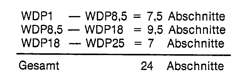
![]()
![]()
Claims (37)
Priority Applications (1)
| Application Number | Priority Date | Filing Date | Title |
|---|---|---|---|
| AT84900506T ATE41894T1 (en) | 1983-01-22 | 1984-01-19 | PROCESS FOR CONTROLLING THE WALL THICKNESS OF HOLLOW-TOP PREFORMS. |
Applications Claiming Priority (2)
| Application Number | Priority Date | Filing Date | Title |
|---|---|---|---|
| DE3302020 | 1983-01-22 | ||
| DE3302020 | 1983-01-22 |
Publications (2)
| Publication Number | Publication Date |
|---|---|
| EP0162045A1 EP0162045A1 (en) | 1985-11-27 |
| EP0162045B1 true EP0162045B1 (en) | 1989-04-05 |
Family
ID=6188900
Family Applications (1)
| Application Number | Title | Priority Date | Filing Date |
|---|---|---|---|
| EP84900506A Expired EP0162045B1 (en) | 1983-01-22 | 1984-01-19 | Method for regulating the wall thickness of tubular preforms |
Country Status (3)
| Country | Link |
|---|---|
| EP (1) | EP0162045B1 (en) |
| DE (1) | DE3477553D1 (en) |
| WO (1) | WO1984002874A1 (en) |
Cited By (4)
| Publication number | Priority date | Publication date | Assignee | Title |
|---|---|---|---|---|
| DE3816273A1 (en) * | 1988-05-12 | 1989-11-30 | Harald Feuerherm | METHOD FOR PRODUCING HOLLOW BODIES FROM THERMOPLASTIC PLASTIC |
| EP0693357A3 (en) * | 1994-06-20 | 1998-04-29 | Feuerherm, Harald | Method for extrusion blow moulding hollow bodies of thermoplastic material |
| DE102008052608B3 (en) * | 2008-10-21 | 2010-05-20 | Feuerherm, Harald, Dipl.-Ing. | Method for manufacturing plastic hollow bodies by blow molding, involves setting measurement in relation with reference value, where deviation starts between measurement and reference value for preform |
| CN107471608A (en) * | 2017-08-28 | 2017-12-15 | 山东通佳重工有限公司 | Production equipment and process is blow molded based on the hollow machine that type embryo curve is precisely controlled |
Families Citing this family (7)
| Publication number | Priority date | Publication date | Assignee | Title |
|---|---|---|---|---|
| US5256346A (en) * | 1988-05-12 | 1993-10-26 | Harald Feuerherm | Method of extrusion blow-molding hollow thermoplastic bodies |
| EP0685315B1 (en) * | 1994-06-03 | 2001-07-18 | Harald Feuerherm | Method for extrusion blow moulding of hollow articles of thermoplastic material |
| DE19544634A1 (en) | 1995-11-30 | 1997-06-05 | Feuerherm Harald | Process for blow molding hollow bodies made of thermoplastic |
| US5902526A (en) * | 1997-04-08 | 1999-05-11 | Ball Corporation | Method and apparatus for producing stretch blow molded articles |
| DE102005037101A1 (en) | 2005-08-03 | 2007-02-08 | Krones Ag | Method and device for wall thickness control |
| DE102008052611B3 (en) * | 2008-10-21 | 2010-04-08 | Feuerherm, Harald, Dipl.-Ing. | Plastic hollow body producing method, involves detecting variations of wall thickness distribution of hollow bodies, and correcting variations by intervening molding process or by changing outflow speed of plastic melt from die gap |
| DE102017217468B4 (en) * | 2017-09-29 | 2021-01-14 | Kautex Textron Gmbh & Co. Kg | Process for the production of hollow plastic bodies |
Family Cites Families (5)
| Publication number | Priority date | Publication date | Assignee | Title |
|---|---|---|---|---|
| DE1704467A1 (en) * | 1967-03-01 | 1971-05-19 | Basf Ag | Arrangement for changing the material distribution of a continuously produced preform made of thermoplastic material |
| DE1900532A1 (en) * | 1969-01-07 | 1970-08-20 | Basf Ag | Altering the material distribution of a - thermoplastic preform from an extruder |
| DE1934284C3 (en) * | 1969-07-07 | 1975-02-27 | Indramat, Gesellschaft Fuer Industrierationalisierung Und Automatisierung Mbh, 8770 Lohr | Device for regulating the wall thickness of the extrudate from plastic machines |
| US3795719A (en) * | 1971-09-09 | 1974-03-05 | Baychem Corp | Method of controlling the blow molding of hollow shaped plastic articles |
| DE3102076A1 (en) * | 1981-01-23 | 1982-09-02 | Krupp Kautex Maschinenbau GmbH, 5300 Bonn | METHOD AND DEVICE FOR PRODUCING A PRE-FORMING FROM THERMOPLASTIC PLASTIC BY EXTRUDING |
-
1984
- 1984-01-19 EP EP84900506A patent/EP0162045B1/en not_active Expired
- 1984-01-19 WO PCT/EP1984/000014 patent/WO1984002874A1/en active IP Right Grant
- 1984-01-19 DE DE8484900506T patent/DE3477553D1/en not_active Expired
Cited By (4)
| Publication number | Priority date | Publication date | Assignee | Title |
|---|---|---|---|---|
| DE3816273A1 (en) * | 1988-05-12 | 1989-11-30 | Harald Feuerherm | METHOD FOR PRODUCING HOLLOW BODIES FROM THERMOPLASTIC PLASTIC |
| EP0693357A3 (en) * | 1994-06-20 | 1998-04-29 | Feuerherm, Harald | Method for extrusion blow moulding hollow bodies of thermoplastic material |
| DE102008052608B3 (en) * | 2008-10-21 | 2010-05-20 | Feuerherm, Harald, Dipl.-Ing. | Method for manufacturing plastic hollow bodies by blow molding, involves setting measurement in relation with reference value, where deviation starts between measurement and reference value for preform |
| CN107471608A (en) * | 2017-08-28 | 2017-12-15 | 山东通佳重工有限公司 | Production equipment and process is blow molded based on the hollow machine that type embryo curve is precisely controlled |
Also Published As
| Publication number | Publication date |
|---|---|
| DE3477553D1 (en) | 1989-05-11 |
| WO1984002874A1 (en) | 1984-08-02 |
| EP0162045A1 (en) | 1985-11-27 |
Similar Documents
| Publication | Publication Date | Title |
|---|---|---|
| EP0345474B1 (en) | Method and apparatus for the extrusion blow moulding of a hollow article | |
| EP0062788B1 (en) | Method and apparatus for producing preferably hollow parisons of a thermoplast | |
| DE2544609C3 (en) | Device for influencing the length of a preform made of thermoplastic material | |
| EP0026828B1 (en) | Device for influencing the weight of a hollow thermoplastic body produced by the extrusion-blowing method | |
| EP0162045B1 (en) | Method for regulating the wall thickness of tubular preforms | |
| EP0897786B1 (en) | Regulation process for an injection moulding machine for plastics | |
| WO2009003662A2 (en) | Method for producing blow-moulded hollow bodies | |
| DE19544634A1 (en) | Process for blow molding hollow bodies made of thermoplastic | |
| EP0451239B1 (en) | Process for the production of hollow bodies from thermoplastic material | |
| DE102008052609B4 (en) | Process for producing plastic hollow bodies by blow molding | |
| EP0407847B1 (en) | Method and apparatus for manufacturing hollow thermoplastic bodies | |
| DE4421171C1 (en) | Process for extrusion blow molding of hollow bodies made of thermoplastic | |
| EP0699514B1 (en) | Computer supported process to determine the optimum working point of an injection molding machine | |
| EP2931492B1 (en) | Extrusion blow molding method and device for the performance thereof | |
| EP0334449B1 (en) | Blowmoulding machine with an adjustable dwellperiod | |
| EP0709177B1 (en) | Method of controlling blow moulding apparatus | |
| DE10046454A1 (en) | Process for rinsing polymer or plastic melt leading parts of film extrusion systems | |
| EP3877142A1 (en) | Switching device and method for switching a flat film machine from an input product to a subsequent product | |
| EP0027575A2 (en) | Apparatus for controlling the production rate of an extruder | |
| DE102008052611B3 (en) | Plastic hollow body producing method, involves detecting variations of wall thickness distribution of hollow bodies, and correcting variations by intervening molding process or by changing outflow speed of plastic melt from die gap | |
| DE2535367C3 (en) | Device for the production of hollow objects by the blow molding process | |
| DE3330076A1 (en) | Process for controlling the wall thickness of a parison in plastics blow moulding machines | |
| DE2535367B2 (en) | DEVICE FOR THE PRODUCTION OF HOLLOW OBJECTS BY THE BLOW METHOD |
Legal Events
| Date | Code | Title | Description |
|---|---|---|---|
| PUAI | Public reference made under article 153(3) epc to a published international application that has entered the european phase |
Free format text: ORIGINAL CODE: 0009012 |
|
| 17P | Request for examination filed |
Effective date: 19850716 |
|
| AK | Designated contracting states |
Designated state(s): AT BE CH DE FR GB LI LU NL SE |
|
| 17Q | First examination report despatched |
Effective date: 19860910 |
|
| R17C | First examination report despatched (corrected) |
Effective date: 19870514 |
|
| GRAA | (expected) grant |
Free format text: ORIGINAL CODE: 0009210 |
|
| AK | Designated contracting states |
Kind code of ref document: B1 Designated state(s): AT BE CH DE FR GB LI LU NL SE |
|
| PG25 | Lapsed in a contracting state [announced via postgrant information from national office to epo] |
Ref country code: SE Effective date: 19890405 Ref country code: NL Effective date: 19890405 |
|
| REF | Corresponds to: |
Ref document number: 41894 Country of ref document: AT Date of ref document: 19890415 Kind code of ref document: T |
|
| REF | Corresponds to: |
Ref document number: 3477553 Country of ref document: DE Date of ref document: 19890511 |
|
| ET | Fr: translation filed | ||
| GBT | Gb: translation of ep patent filed (gb section 77(6)(a)/1977) | ||
| NLV1 | Nl: lapsed or annulled due to failure to fulfill the requirements of art. 29p and 29m of the patents act | ||
| PLBE | No opposition filed within time limit |
Free format text: ORIGINAL CODE: 0009261 |
|
| STAA | Information on the status of an ep patent application or granted ep patent |
Free format text: STATUS: NO OPPOSITION FILED WITHIN TIME LIMIT |
|
| 26N | No opposition filed | ||
| EPTA | Lu: last paid annual fee | ||
| PGFP | Annual fee paid to national office [announced via postgrant information from national office to epo] |
Ref country code: LU Payment date: 19990121 Year of fee payment: 16 |
|
| PGFP | Annual fee paid to national office [announced via postgrant information from national office to epo] |
Ref country code: CH Payment date: 19990125 Year of fee payment: 16 |
|
| PG25 | Lapsed in a contracting state [announced via postgrant information from national office to epo] |
Ref country code: LU Free format text: LAPSE BECAUSE OF NON-PAYMENT OF DUE FEES Effective date: 20000119 |
|
| PG25 | Lapsed in a contracting state [announced via postgrant information from national office to epo] |
Ref country code: LI Free format text: LAPSE BECAUSE OF NON-PAYMENT OF DUE FEES Effective date: 20000131 Ref country code: CH Free format text: LAPSE BECAUSE OF NON-PAYMENT OF DUE FEES Effective date: 20000131 |
|
| REG | Reference to a national code |
Ref country code: CH Ref legal event code: PL |
|
| PGFP | Annual fee paid to national office [announced via postgrant information from national office to epo] |
Ref country code: AT Payment date: 20010123 Year of fee payment: 18 |
|
| REG | Reference to a national code |
Ref country code: GB Ref legal event code: IF02 |
|
| PGFP | Annual fee paid to national office [announced via postgrant information from national office to epo] |
Ref country code: GB Payment date: 20020104 Year of fee payment: 19 |
|
| PG25 | Lapsed in a contracting state [announced via postgrant information from national office to epo] |
Ref country code: AT Free format text: LAPSE BECAUSE OF NON-PAYMENT OF DUE FEES Effective date: 20020119 |
|
| PG25 | Lapsed in a contracting state [announced via postgrant information from national office to epo] |
Ref country code: GB Free format text: LAPSE BECAUSE OF NON-PAYMENT OF DUE FEES Effective date: 20030119 |
|
| PGFP | Annual fee paid to national office [announced via postgrant information from national office to epo] |
Ref country code: FR Payment date: 20030120 Year of fee payment: 20 |
|
| PGFP | Annual fee paid to national office [announced via postgrant information from national office to epo] |
Ref country code: BE Payment date: 20030128 Year of fee payment: 20 |
|
| PGFP | Annual fee paid to national office [announced via postgrant information from national office to epo] |
Ref country code: DE Payment date: 20030327 Year of fee payment: 20 |
|
| GBPC | Gb: european patent ceased through non-payment of renewal fee | ||
| BE20 | Be: patent expired |
Owner name: *FEUERHERM HARALD Effective date: 20040119 |